
Related Manuals for Huawei AP8030DN


Summary of Contents for Huawei AP8030DN
- Page 1 Huawei AP8030DN & AP8130DN Hardware Installation and Maintenance Guide Issue Date 2014-12-05 HUAWEI TECHNOLOGIES CO., LTD.
- Page 2 All other trademarks and trade names mentioned in this document are the property of their respective holders. Notice The purchased products, services and features are stipulated by the contract made between Huawei and the customer. All or part of the products, services and features described in this document may not be within the purchase scope or the usage scope.
-
Page 3: About This Document
Huawei AP8030DN & AP8130DN Hardware Installation and Maintenance Guide About This Document About This Document Intended Audience This document describes hardware features of the AP8030DN and AP8130DN and provides basic installation methods. This document is intended for: Network planning engineers Hardware installation engineers... - Page 4 Issue 02 (2014-12-05) This version has the following updates: The following information is modified: Installation of the angle adjusting component with AP8030DN is added. The following information is added: 1.4 Ordering Information. Issue 01 (2014-08-20)
-
Page 5: Table Of Contents
Huawei AP8030DN & AP8130DN Hardware Installation and Maintenance Guide Contents Contents About This Document........................ii 1 AP8130DN & AP8030DN Overview..................1 1.1 Device Structure................................2 1.2 Indicator Description..............................4 1.3 Basic Specifications................................7 1.4 Ordering Information..............................8 2 AP Installation..........................10 2.1 Preparing for Installation..............................11 2.2 Installation Flowchart..............................12 2.3 Unpacking the Equipment............................13... - Page 6 5.4.3 Engineering Labels for Network Cables.........................111 5.4.4 Engineering Labels for User Cables........................112 5.4.5 Engineering Labels for Power Cables........................113 5.5 Guide to Using Optical Modules..........................116 5.6 Fault Tag..................................119 Issue 02 (2014-12-05) Huawei Proprietary and Confidential Copyright © Huawei Technologies Co., Ltd.
-
Page 7: Ap8130Dn & Ap8030Dn Overview
AP8130DN & AP8030DN Overview About This Chapter Huawei AP8030DN and AP8130DN is the latest-generation 802.11ac outdoor access point (AP) that supports 3x3 MIMO. The AP is physically hardened and features enhanced outdoor coverage performance. It supports 2.4 GHz and 5 GHz frequency bands, complies with IEEE 802.11a/b/g/n/ac, and can work as wireless bridges. -
Page 8: Device Structure
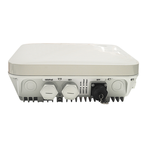
Hardware Installation and Maintenance Guide 1 AP8130DN & AP8030DN Overview 1.1 Device Structure Figure 1-1 Figure 1-2 shows the appearance of the AP8030DN and AP8130DN. Figure 1-1 AP8030DN appearance GE0/PoE D ef aul t Consol e Figure 1-2 AP8130DN appearance GE0/PoE 2.4G/5G... - Page 9 Huawei AP8030DN & AP8130DN Hardware Installation and Maintenance Guide 1 AP8130DN & AP8030DN Overview Default Console Table 1-1 describes interfaces on the AP8030DN and AP8130DN. Table 1-1 Descriptions of interfaces Name Description GE0/PoE 10/100/1000M bit/s interface: connects to the wired Ethernet. The interface can connect to...
-
Page 10: Indicator Description
1.2 Indicator Description The AP8030DN and AP8130DN provides multiple indicators: SYS indicator, Link/ACT indicator, and Wireless indicator. The following tables describe indicators on the AP8030DN and AP8130DN. NOTE l Indicator colors may vary slightly at different temperature. - Page 11 Huawei AP8030DN & AP8130DN Hardware Installation and Maintenance Guide 1 AP8130DN & AP8030DN Overview Type Color Status Description Blinking The system is running properly, the Ethernet once every connection is normal, and no STA is associated with 5s (0.2 Hz) the AP.
- Page 12 Huawei AP8030DN & AP8130DN Hardware Installation and Maintenance Guide 1 AP8130DN & AP8030DN Overview Table 1-4 Traffic volume indicator Color Status Description Yellow/green Radios are disabled, and no STA is connected to the AP. Yellow/green Steady on The AP has STAs connected to the 2.4 GHz radio or 5 GHz radio, but no data is being transmitted.
-
Page 13: Basic Specifications
The Fat AP does not support WDS/Mesh functions; therefore, the Wireless indicator of the Fat AP does not indicate the signal strength. 1.3 Basic Specifications Table 1-6 Table 1-7 provides basic specifications of the AP8030DN and AP8130DN. Table 1-6 Basic Specifications of the AP8030DN Item Description Technical... -
Page 14: Ordering Information
Operating humidity 0% to 100% (non-condensing) IP rating IP67 Atmospheric 53 kPa to 106 kPa pressure 1.4 Ordering Information To place an order, contact the Huawei local office. Issue 02 (2014-12-05) Huawei Proprietary and Confidential Copyright © Huawei Technologies Co., Ltd. - Page 15 Huawei AP8030DN & AP8130DN Hardware Installation and Maintenance Guide 1 AP8130DN & AP8030DN Overview Part Number Description 02350ALD Assembling Components,AP8030DN,AP8030DN,AP8030DN Mainframe(11ac,General AP Outdoor,3x3 Double Frequency,Built-in Antenna) 02359462 Assembling Components,AP8130DN,AP8130DN,AP8130DN Mainframe(11ac,General AP Outdoor,3x3 Double Frequency,External Antenna) Issue 02 (2014-12-05) Huawei Proprietary and Confidential...
-
Page 16: Ap Installation
2.4 Determining the Installation Position 2.5 Installing the AP 2.6 Connecting Cables 2.7 Installing the Security Lock 2.8 Checking the AP After Installation 2.9 Powering on the AP Issue 02 (2014-12-05) Huawei Proprietary and Confidential Copyright © Huawei Technologies Co., Ltd. -
Page 17: Preparing For Installation
Table 2-1 Tools Phillips screwdriver (M4) Torque screwdriver Torque socket (M6) 3mm/5mm (M3-M6) Hammer drill (φ8) Utility knife Cable cutter Diagonal pliers RJ45 crimping tool Wire stripper Issue 02 (2014-12-05) Huawei Proprietary and Confidential Copyright © Huawei Technologies Co., Ltd. -
Page 18: Installation Flowchart
Adjustable wrench Rubber mallet ESD gloves Level Marker Torque wrench (Use an N-type open-end torque wrench.) 2.2 Installation Flowchart Figure 2-1 shows the flowchart for installing an AP8130DN. Issue 02 (2014-12-05) Huawei Proprietary and Confidential Copyright © Huawei Technologies Co., Ltd. -
Page 19: Unpacking The Equipment
Usually, the packing carton contains all items listed in the packing list shown in Table 2-2. Table 2-2 Packing list Item Quantity AP device Mounting bracket Issue 02 (2014-12-05) Huawei Proprietary and Confidential Copyright © Huawei Technologies Co., Ltd. -
Page 20: Determining The Installation Position
The AP8030DN and AP8130DN can be installed against a pole or a wall. The diameter of the pole used should be from 48 mm to 114 mm. The AP must be installed by professional installation personnel, and the installation position is determined according to the site survey. - Page 21 Hardware Installation and Maintenance Guide 2 AP Installation Figure 2-2 Dimensions of an AP8030DN (unit: mm) Figure 2-3 Dimensions of an AP8130DN (unit: mm) The AP8030DN and AP8130DN have the same space requirements. Figure 2-4 shows space requirements for installing an AP8130DN.
-
Page 22: Installing The Ap
2.5.1 Wall Mounting Wall mounting requires use of the mounting bracket and matching expansion bolts. When the AP8030DN is mounted to a wall, the angle adjusting component is required. The procedures are as follows: Fix the mounting bracket to the wall, adjust the installation position, and use the marker to mark the drilling positions where expansion bolts are installed. - Page 23 Then, remove the nut, spring washer, and flat washer in order. Ø8 35mm~40mm Use four M4x12 hexagon socket head cap screws to fasten the AP-side module of the mounting bracket to the AP. Issue 02 (2014-12-05) Huawei Proprietary and Confidential Copyright © Huawei Technologies Co., Ltd.
- Page 24 Hang the wall-side module of the mounting bracket on the expansion bolts and use a wrench to fasten the flat washers, spring washers, and nuts in order. 5N•m Install the AP. The AP8030DN installation requires use of the angle adjusting component but the AP8130DN does not. Install the AP8030DN: Hang the angle adjusting component on the mounting bracket and use a Phillips screwdriver to tighten the screw at position 3, with a tightening torque of 1.4N.m.
- Page 25 To adjust the horizontal angle of the AP, use the M6 hex key to remove the screw at position 2, lift the angle adjusting component vertically, and adjust the angle adjusting component horizontally. Issue 02 (2014-12-05) Huawei Proprietary and Confidential Copyright © Huawei Technologies Co., Ltd.
- Page 26 Install the AP8130DN: Hang the AP with the AP-side mounting bracket module to the wall-side mounting bracket module and tighten the screws to secure the AP. 1N•m Issue 02 (2014-12-05) Huawei Proprietary and Confidential Copyright © Huawei Technologies Co., Ltd.
-
Page 27: Pole Mounting
Close the lid. Use the hex torque screwdriver to tighten the screws with a torque of 5 N•m. 5N•m Install the AP. The AP8030DN installation requires use of the angle adjusting component but the AP8130DN does not. Install the AP8030DN: Hang the angle adjusting component on the mounting bracket and use a Phillips screwdriver to tighten the screw at position 3, with a tightening torque of 1.4N.m. - Page 28 To adjust the horizontal angle of the AP, use the M6 hex key to remove the screw at position 2, lift the angle adjusting component vertically, and adjust the angle adjusting component horizontally. Issue 02 (2014-12-05) Huawei Proprietary and Confidential Copyright © Huawei Technologies Co., Ltd.
- Page 29 Install the AP8130DN: Hang the AP with the AP-side mounting bracket module to the wall-side mounting bracket module and tighten the screws to secure the AP. 1N•m Issue 02 (2014-12-05) Huawei Proprietary and Confidential Copyright © Huawei Technologies Co., Ltd.
-
Page 30: Connecting Cables
AP against a vertical pole. 2.6 Connecting Cables Figure 2-5 AP8130DN external cable arrangement Feed line Feed line Feed line Feed line Optical fiber Network cable Feed line Feed line Issue 02 (2014-12-05) Huawei Proprietary and Confidential Copyright © Huawei Technologies Co., Ltd. -
Page 31: Connecting Rf Cables
RF cable deployment requirements It is recommended that you connect a 50 ohm RF load to an idle antenna interface and wrap the RF load with insulation tape and waterproof tape. Huawei offers 50 ohm RF loads for you to purchase. -
Page 32: Connecting Optical Fibers And Network Cables
When connecting an optical fiber to the AP, loosen the device-side fiber connector, put the optical fiber through the fiber connector, and tighten the fiber connector on the device according to the figure. Issue 02 (2014-12-05) Huawei Proprietary and Confidential Copyright © Huawei Technologies Co., Ltd. - Page 33 Put the network cable through waterproof PG connectors. Connect the RJ45 connector to the ETH/PoE interface on the AP and secure the waterproof PG connector. See figures b, c, and d. Issue 02 (2014-12-05) Huawei Proprietary and Confidential Copyright © Huawei Technologies Co., Ltd.
-
Page 34: Connecting Ground Cables
Do not use another device for an electrical connection with the ground cable. All metal components in the shell must be securely connected to the ground terminal. Issue 02 (2014-12-05) Huawei Proprietary and Confidential Copyright © Huawei Technologies Co., Ltd. - Page 35 Use a utility knife to strip the sheath off the network cable for about 32 mm (1.26in.) to expose the shield layer. NOTICE Do not damage the shield layer when stripping the sheath off the cable. Issue 02 (2014-12-05) Huawei Proprietary and Confidential Copyright © Huawei Technologies Co., Ltd.
- Page 36 The degree between the ground cable and the network cable cable is not greater than 15°. When the network cable is routed vertically, the ground cable must be routed downwards. Issue 02 (2014-12-05) Huawei Proprietary and Confidential Copyright © Huawei Technologies Co., Ltd.
-
Page 37: Installing Outdoor Antennas
If there is no parapet around the roof, fix the pole on the ground or a concrete bed with expansion screws and steel wires, and then fix the directional outdoor antenna on the pole with an antenna support. Issue 02 (2014-12-05) Huawei Proprietary and Confidential Copyright © Huawei Technologies Co., Ltd. - Page 38 Do no weld a lightning rod directly on the antenna pole (there should not be metal subjects within 1 m around an omnidirectional antenna). Instead, install an independent lightning Issue 02 (2014-12-05) Huawei Proprietary and Confidential Copyright © Huawei Technologies Co., Ltd.
-
Page 39: Installing The Security Lock
Fasten the cable of the security lock to an immovable object around. Insert the security lock into the security slot and lock it. Security lock Lock hole Issue 02 (2014-12-05) Huawei Proprietary and Confidential Copyright © Huawei Technologies Co., Ltd. -
Page 40: Checking The Ap After Installation
After the AP installation is complete, observe indicators on the AP to determine the system running status. For details, see 1.2 Indicator Description. NOTE Do not frequently power on and off an AP. Issue 02 (2014-12-05) Huawei Proprietary and Confidential Copyright © Huawei Technologies Co., Ltd. -
Page 41: Logging In To The Ap
3.1 Logging In to the AP Through the Console Port 3.2 Logging In to the AP Using STelnet 3.3 Logging In to the AP Using Telnet 3.4 Logging In to the AP Using a Web Client Issue 02 (2014-12-05) Huawei Proprietary and Confidential Copyright © Huawei Technologies Co., Ltd. -
Page 42: Logging In To The Ap Through The Console Port
Use the SSH client software to log in to the device through STelnet from a terminal. The third-party software PuTTY is used as an example here. Issue 02 (2014-12-05) Huawei Proprietary and Confidential Copyright © Huawei Technologies Co., Ltd. - Page 43 (The following information is only for reference.) login as: admin Sent username "admin" admin@169.254.1.1's password: <Huawei> NOTE It is recommended that you change the initial user name and password after login. Issue 02 (2014-12-05) Huawei Proprietary and Confidential Copyright © Huawei Technologies Co., Ltd.
-
Page 44: Logging In To The Ap Using Telnet
Enter the default user name and password. The default user name is admin, and the default password is admin@huawei.com. If the user view is displayed, you have logged in successfully. You are advised to change the user name and password on your first login. - Page 45 169.254.1.1 and the mask is 255.255.0.0. The web management system provides a default user account, with the user name admin and password admin@huawei.com. You are advised to change the user name and password on your first login. Assign your PC an IP address on the same network segment as the default IP address of the web management system, and connect the PC to the GE interface.
-
Page 46: Hardware Failures
About This Chapter This section describes common methods for troubleshooting typical hardware faults. 4.1 An device Fails to Be Powered On 4.2 An Optical Interface Cannot Turn Up Issue 02 (2014-12-05) Huawei Proprietary and Confidential Copyright © Huawei Technologies Co., Ltd. -
Page 47: An Device Fails To Be Powered On
Huawei agent through Hotline&Email and ask them to replace the power adapter. If the device still cannot be powered on, the device itself is faulty. Contact Huawei technical support or Huawei agent through Hotline&Email and ask them to replace the device. - Page 48 1.25 Gbit/s. It is recommended that you use an optical module with the same speed as the optical interface to ensure efficient optical transmission. If the interface remains Down, contact Huawei technical support through Hotline&Email. Issue 02 (2014-12-05) Huawei Proprietary and Confidential...
-
Page 49: Appendix
5.1 On-site Cable Assembly and Installation 5.2 Environmental Requirements for Device Operation 5.3 Equipment Grounding Specifications 5.4 Engineering Labels for Cables 5.5 Guide to Using Optical Modules 5.6 Fault Tag Issue 02 (2014-12-05) Huawei Proprietary and Confidential Copyright © Huawei Technologies Co., Ltd. -
Page 50: On-Site Cable Assembly And Installation
Precautions for Assembly Use dedicated tools or tools delivered by Huawei and follow the methods given here during assembly. Hold terminals of cables instead of pulling the cables when installing or removing cable components. -
Page 51: Assembling Power Cables
Step 1 Based on the cross-sectional area of the cable conductor, strip a length of insulation coating C to expose the conductor D of length L1, as shown in Figure 5-2. The recommended values of L1 are listed in Table 5-1. Issue 02 (2014-12-05) Huawei Proprietary and Confidential Copyright © Huawei Technologies Co., Ltd. - Page 52 When you strip a power cable, do not damage the conductor of the cable. l If the bare crimping terminal is not provided by Huawei, the value of L1 is 1 mm (0.04 in.) to 2 mm (0.08 in.) greater than the value of L.
- Page 53 The shapes of crimped parts may vary with the crimping dies. Figure 5-4 Crimping the joint parts of the bare crimping terminal and the conductor (OT terminal) Issue 02 (2014-12-05) Huawei Proprietary and Confidential Copyright © Huawei Technologies Co., Ltd.
- Page 54 Figure 5-6 Components of a JG terminal and a power cable A. JG terminal B. Heat-shrinkable tube C. Insulation layer of a power cable D. Conductor of a power cable Issue 02 (2014-12-05) Huawei Proprietary and Confidential Copyright © Huawei Technologies Co., Ltd.
- Page 55 NOTICE l When you strip a power cable, do not damage the conductor of the cable. l If the bare crimping terminal is not provided by Huawei, you can adjust the value of L as required. Figure 5-7 Stripping a power cable (JG terminal)
- Page 56 Step 5 Push the heat shrink tubing towards the connector until the tube covers the crimped part, and then heat the tube by using a heat gun, as shown in Figure 5-10. Figure 5-10 Heating the heat shrink tubing (JG terminal) Issue 02 (2014-12-05) Huawei Proprietary and Confidential Copyright © Huawei Technologies Co., Ltd.
- Page 57 5-12. The recommended values of L1 are listed Table 5-3. NOTICE When you strip a power cable, do not damage the conductor of the cable. Figure 5-12 Stripping a power cable (cord end terminal) Issue 02 (2014-12-05) Huawei Proprietary and Confidential Copyright © Huawei Technologies Co., Ltd.
- Page 58 Figure 5-13 Put the cord end terminal onto the conductor Step 3 Crimp the joint parts of the cord end terminal and the conductor, as shown in Figure 5-14. Issue 02 (2014-12-05) Huawei Proprietary and Confidential Copyright © Huawei Technologies Co., Ltd.
-
Page 59: Assembling Ethernet Cables
5.3 (0.21) 16 (0.025) 6 (0.24) 25 (0.039) 8.7 (0.34) 35 (0.054) 10 (0.39) ----End 5.1.3 Assembling Ethernet Cables Assembling the Shielded RJ45 Connector and Ethernet Cable Issue 02 (2014-12-05) Huawei Proprietary and Confidential Copyright © Huawei Technologies Co., Ltd. - Page 60 Step 2 Remove a 30 mm (1.18 in.) long section of the jacket, cut off the nylon twine inside the jacket, and cut a no more than 5 mm (0.20 in.) cleft in the jacket, as shown in Figure 5-17. Issue 02 (2014-12-05) Huawei Proprietary and Confidential Copyright © Huawei Technologies Co., Ltd.
- Page 61 The exposed twisted-pair cable is about 20 mm (0.79 in.) long, as shown Figure 5-19. Issue 02 (2014-12-05) Huawei Proprietary and Confidential Copyright © Huawei Technologies Co., Ltd.
- Page 62 Step 6 Align the four pairs of cables in the holder, as shown in Figure 5-22. The connections between the wires and the pins are shown in Figure 5-23 and listed in Table 5-5. Issue 02 (2014-12-05) Huawei Proprietary and Confidential Copyright © Huawei Technologies Co., Ltd.
- Page 63 Table 5-5 Connections between wires and pins (using a straight-through cable as an example) Matching Pins of Wires Wire Color White-Orange Orange White-Green Blue White-Blue Green White-Brown Issue 02 (2014-12-05) Huawei Proprietary and Confidential Copyright © Huawei Technologies Co., Ltd.
- Page 64 Step 9 Push the metal shell towards the connector body until the wire holder and the connector body are engaged completely. Crimp the connector, as shown in Figure 5-26. Issue 02 (2014-12-05) Huawei Proprietary and Confidential Copyright © Huawei Technologies Co., Ltd.
- Page 65 Step 11 To complete the assembly of the other end, repeat Step 1 through Step ----End Assembling an Unshielded RJ45 Connector and Ethernet Cable Context Figure 5-28 shows the components of an unshielded RJ45 connector and cable. Issue 02 (2014-12-05) Huawei Proprietary and Confidential Copyright © Huawei Technologies Co., Ltd.
- Page 66 Table 5-6. Figure 5-30 Connections between wires and pins (unit: mm (in.)) White-Orange Orange White-Green Blue White-Blue Green White-Brown Pin 8 Brown Pin 1 Issue 02 (2014-12-05) Huawei Proprietary and Confidential Copyright © Huawei Technologies Co., Ltd.
- Page 67 Context To ensure proper contact between the crimped wires and the wire conductors, the heights and sizes of the contact strips must be standard and the same. Issue 02 (2014-12-05) Huawei Proprietary and Confidential Copyright © Huawei Technologies Co., Ltd.
- Page 68 NOTE All unqualified pieces must be crimped again. Figure 5-32 Contact strips of different heights Figure 5-33 Contact strips of the same height Issue 02 (2014-12-05) Huawei Proprietary and Confidential Copyright © Huawei Technologies Co., Ltd.
- Page 69 Step 4 Check whether the contact strips and the plastic separators are well aligned and intact. If a separator is skew and cannot be fixed, replace it with a new RJ45 connector. Figure 5-36 shows an unqualified piece. Figure 5-36 Skew plastic separators Issue 02 (2014-12-05) Huawei Proprietary and Confidential Copyright © Huawei Technologies Co., Ltd.
- Page 70 Testing the Connection of Assembled Cables Context Huawei provides two types of Ethernet cables: straight-through cables and crossover cables. Straight-through cables are connected in a one-to-one manner. They are used to connect terminals such as a computer or switch to network devices.
- Page 71 Turn the switch to the S position to slow down lighting of the indicators so that you can see the indicators more clearly, as shown in Figure 5-39. Issue 02 (2014-12-05) Huawei Proprietary and Confidential Copyright © Huawei Technologies Co., Ltd.
- Page 72 At the master (left) section of the tester, the indicators turn on in the sequence of 1-8-G. At the slave (right) section of the tester, the indicators turn on in the sequence of 3-6-1-4-5-2-7-8-G. Otherwise, the Ethernet cable is unqualified. Issue 02 (2014-12-05) Huawei Proprietary and Confidential Copyright © Huawei Technologies Co., Ltd.
-
Page 73: Installing Cable Accessories
For example, in this document, the adapters of cable connectors have separate interfaces. In the actual situation, the adapters may have interfaces fixed on equipment. Use dedicated tools provided or specified by Huawei and follow the installation procedure described here. - Page 74 Sharp objects must not be touched in cable wiring to ensure that cables are not damaged. To protect power cables, power cables of the active and standby power modules are laid separately. Installing Power Adapters Installing the OT Terminal Issue 02 (2014-12-05) Huawei Proprietary and Confidential Copyright © Huawei Technologies Co., Ltd.
- Page 75 Figure 5-43 Installing an OT terminal, showing the orientation of crimping sleeve Place the spring washer and flat washer in turn, mount a matching screw, and fasten it clockwise, as shown in Figure 5-44. Issue 02 (2014-12-05) Huawei Proprietary and Confidential Copyright © Huawei Technologies Co., Ltd.
- Page 76 – Bend the upper OT terminal at a 45- or 90-degree angle, as shown in Figure 5-46. – Cross the two terminals, as shown in Figure 5-47. Issue 02 (2014-12-05) Huawei Proprietary and Confidential Copyright © Huawei Technologies Co., Ltd.
- Page 77 Step 1 Hold a cord end terminal upright and place it on a terminal jack, as shown in Figure 5-48. To ensure bump contact and dense connection, place the plain side of the terminal outwards. Issue 02 (2014-12-05) Huawei Proprietary and Confidential Copyright © Huawei Technologies Co., Ltd.
- Page 78 Step 3 Move the cable slightly and ensure that it is securely connected. Step 4 Before you remove a cord end terminal, loosen the screw in the counterclockwise direction. ----End Installing Ethernet Adapters Issue 02 (2014-12-05) Huawei Proprietary and Confidential Copyright © Huawei Technologies Co., Ltd.
- Page 79 Pull the connector slightly and ensure that it is securely connected, as shown in Figure 5-52. Issue 02 (2014-12-05) Huawei Proprietary and Confidential Copyright © Huawei Technologies Co., Ltd.
- Page 80 Installing an Unshielded Ethernet Connector Procedure Step 1 Hold the male and female connectors, with the male connector facing the female connector, as shown in Figure 5-54. Issue 02 (2014-12-05) Huawei Proprietary and Confidential Copyright © Huawei Technologies Co., Ltd.
- Page 81 Step 3 A crisp click indicates that the connector is locked by the locking key. Pull the connector slightly and ensure that it is securely connected. Figure 5-56 shows an installed Ethernet connector. Figure 5-56 Installed unshielded Ethernet connector Issue 02 (2014-12-05) Huawei Proprietary and Confidential Copyright © Huawei Technologies Co., Ltd.
- Page 82 Step 2 Clean the pins again by using dust-free cotton. If necessary, clean the pins by using an air gun. Ensure that the pins are free from any fiber or debris. ----End Issue 02 (2014-12-05) Huawei Proprietary and Confidential Copyright © Huawei Technologies Co., Ltd.
- Page 83 Figure 5-59 Feeding the male connector into the female connector Step 4 Fasten the locking nut in the clockwise direction and ensure that the connector is securely installed, as shown in Figure 5-60. Issue 02 (2014-12-05) Huawei Proprietary and Confidential Copyright © Huawei Technologies Co., Ltd.
- Page 84 Step 1 Remove the dustproof cap of the LC fiber connector and store it for future use. Step 2 Align the core pin of the male connector with that of the female connector, as shown in Figure 5-62. Issue 02 (2014-12-05) Huawei Proprietary and Confidential Copyright © Huawei Technologies Co., Ltd.
- Page 85 Figure 5-63 Feeding the male connector into the female connector Step 4 A clicking sound indicates that the male connector is locked, as shown in Figure 5-64. Figure 5-64 Installed LC connector Issue 02 (2014-12-05) Huawei Proprietary and Confidential Copyright © Huawei Technologies Co., Ltd.
- Page 86 Step 3 Feed the fiber connector into the female connector, with your fingers holding the shell of the fiber connector (not the pigtail). When you hear a click, the fiber connector is secured by the Issue 02 (2014-12-05) Huawei Proprietary and Confidential Copyright © Huawei Technologies Co., Ltd.
- Page 87 Step 1 Remove the dustproof cap of the MPO fiber connector and store it for future use. Step 2 Align the core pin of the male connector with that of the female connector, as shown in Figure 5-69. Issue 02 (2014-12-05) Huawei Proprietary and Confidential Copyright © Huawei Technologies Co., Ltd.
- Page 88 Figure 5-70 Installed MPO fiber connector Step 4 To disassemble an MPO fiber connector, hold the shell labeled "PULL" and remove the male connector, as shown in Figure 5-71. Issue 02 (2014-12-05) Huawei Proprietary and Confidential Copyright © Huawei Technologies Co., Ltd.
-
Page 89: Replacing The Mold Of The Crimping Pliers
Step 2 Hold the handles of the COAX crimping tools to open the self-locking mechanism. The jaw of the COAX crimping tools opens automatically, as shown in Figure 5-73. Issue 02 (2014-12-05) Huawei Proprietary and Confidential Copyright © Huawei Technologies Co., Ltd. - Page 90 Figure 5-74 Removing the mould from the COAX crimping tools Step 4 Place the mould to be installed into the jaw of the COAX crimping tools and align the screw holes, as shown in Figure 5-75. Issue 02 (2014-12-05) Huawei Proprietary and Confidential Copyright © Huawei Technologies Co., Ltd.
- Page 91 Step 6 Hold the handles of the COAX crimping tools with one hand. Tighten the two fastening screws in the clockwise direction. Figure 5-77 Figure 5-78shows the mould installed in the COAX crimping tools. Issue 02 (2014-12-05) Huawei Proprietary and Confidential Copyright © Huawei Technologies Co., Ltd.
-
Page 92: Environmental Requirements For Device Operation
The equipment room should also follow local regulations concerning the industrial construction, environmental protection, fire fighting, and civil air defense. Construction must conform to government standards, regulations, and other requirements. Issue 02 (2014-12-05) Huawei Proprietary and Confidential Copyright © Huawei Technologies Co., Ltd. - Page 93 To ensure easy maintenance and management, place the telecom equipment in different rooms. Figure 5-79 shows the layout of the equipment room. Issue 02 (2014-12-05) Huawei Proprietary and Confidential Copyright © Huawei Technologies Co., Ltd.
- Page 94 You can connect them to ground using a one megohm current-limiting resistor and connection line. Load-bearing The floor must bear loads larger than 150 kg/m (0.21 bf/in. capacity Issue 02 (2014-12-05) Huawei Proprietary and Confidential Copyright © Huawei Technologies Co., Ltd.
- Page 95 Dust on devices may cause electrostatic discharge and result in poor contact for connectors or metal connection points. This problem can shorten the life span of devices and cause faults. Issue 02 (2014-12-05) Huawei Proprietary and Confidential Copyright © Huawei Technologies Co., Ltd.
- Page 96 Table 5-12 Requirements for corrosive gas concentration Chemical active material Unit Concentration ≤0.20 mg/m ≤0.006 mg/m ≤0.05 mg/m ≤0.01 mg/m Issue 02 (2014-12-05) Huawei Proprietary and Confidential Copyright © Huawei Technologies Co., Ltd.
- Page 97 Keep the equipment far away from strong power radio transmitters, radar units, and high- frequency and high-current equipment. Use electromagnetic shielding if necessary. Requirements for Lightning Proof Grounding Table 5-13 shows the requirements for lightning proof grounding. Issue 02 (2014-12-05) Huawei Proprietary and Confidential Copyright © Huawei Technologies Co., Ltd.
- Page 98 Do not install the fuse or switch on the ground cable. l All ground cables should be as short as possible, and arranged directly. Issue 02 (2014-12-05) Huawei Proprietary and Confidential Copyright © Huawei Technologies Co., Ltd.
- Page 99 40 mm x 4 mm (1.58 in. x 0.158 in.) or 50 mm x 5 mm (1.97 in. x 0.197 in.). Issue 02 (2014-12-05) Huawei Proprietary and Confidential Copyright © Huawei Technologies Co., Ltd.
-
Page 100: Requirements For Power Supply
For power distribution capacity in the equipment room, both the working current and fault current of the devices should be considered. Ensure that independent AC power supplies protect Issue 02 (2014-12-05) Huawei Proprietary and Confidential Copyright © Huawei Technologies Co., Ltd. - Page 101 When an inverter or a UPS is used, the active inverter is determined by the maximum power and a backup inverter is required. Issue 02 (2014-12-05) Huawei Proprietary and Confidential Copyright © Huawei Technologies Co., Ltd.
- Page 102 Use distributed power supply mode. Use multiple DC power supply systems and put power equipment in multiple locations. Adopt a standard DC power supply system, and set the output voltage to the communications equipment within the required range. Issue 02 (2014-12-05) Huawei Proprietary and Confidential Copyright © Huawei Technologies Co., Ltd.
-
Page 103: Equipment Grounding Specifications
The grounding resistance in an area where the earth resistance rate is high should be less than 10 ohms. 5.3.3 Grounding Specifications for Devices Table 5-17 shows the equipment grounding specifications. Issue 02 (2014-12-05) Huawei Proprietary and Confidential Copyright © Huawei Technologies Co., Ltd. -
Page 104: Grounding Specifications For Communications Power Supply
If the power supply and the equipment are in the same equipment room, use the same protection ground bar for them if possible. Issue 02 (2014-12-05) Huawei Proprietary and Confidential Copyright © Huawei Technologies Co., Ltd. -
Page 105: Grounding Specifications For Signal Cables
Table 5-20 Specifications for laying out ground cables Description The grounding wire should not run parallel to or twist around the signal cable. Issue 02 (2014-12-05) Huawei Proprietary and Confidential Copyright © Huawei Technologies Co., Ltd. -
Page 106: Engineering Labels For Cables
Thickness: 0.09 mm (0.004 in.) Color: chalk white Material: polyester (PET) Ambient temperature: -29°C (-20.2°F) to +149°C (300.2°F) Compatible with laser printing and handwriting with markers Pass UL and CSA authentication Issue 02 (2014-12-05) Huawei Proprietary and Confidential Copyright © Huawei Technologies Co., Ltd. - Page 107 The identification plate has an embossed area 0.2 mm x 0.6 mm (0.008 in. x 0.02 in.) around (symmetric on both sides), and the area in the middle is for affixing the label, as shown in Figure 5-82. Issue 02 (2014-12-05) Huawei Proprietary and Confidential Copyright © Huawei Technologies Co., Ltd.
- Page 108 Template for Printing Use a template to print labels. You can obtain the template from the Huawei local office. The templates are made in Microsoft Word and the following requirements should be met: Issue 02 (2014-12-05) Huawei Proprietary and Confidential Copyright ©...
- Page 109 After the page setup has been made correctly, save it for future use. This page setup is only necessary the first time you use the template to print the labels. Issue 02 (2014-12-05) Huawei Proprietary and Confidential Copyright © Huawei Technologies Co., Ltd.
- Page 110 Table 5-21 Standard typeface for handwriting Determine the size of characters based on the number of letters or digits and ensure that the characters are clear, distinct, and tidy. Issue 02 (2014-12-05) Huawei Proprietary and Confidential Copyright © Huawei Technologies Co., Ltd.
- Page 111 – The identification card should be downward when you lay out the cable horizontally. Figure 5-85 Text area of the label Procedure for attaching labels Figure 5-86 shows the methods and procedures for attaching labels. Issue 02 (2014-12-05) Huawei Proprietary and Confidential Copyright © Huawei Technologies Co., Ltd.
- Page 112 The identification card is to the right of the cable in vertical cabling. The identification card is on the top of the cable in horizontal cabling. Make sure that the label is facing out. Issue 02 (2014-12-05) Huawei Proprietary and Confidential Copyright © Huawei Technologies Co., Ltd.
- Page 113 The side with "TO:" that is facing outside carries the location information of the opposite end; and the other side carries the location information of the local end. Issue 02 (2014-12-05) Huawei Proprietary and Confidential Copyright © Huawei Technologies Co., Ltd.
-
Page 114: Engineering Labels For Optical Fibers
Numbered in bottom-up order with two digits, for number example, 01. C: physical slot Numbered in the top-down and left-right order starting number from 01. For example, 01 is the slot with number 1. Issue 02 (2014-12-05) Huawei Proprietary and Confidential Copyright © Huawei Technologies Co., Ltd. - Page 115 ODF. Table 5-23 Information on labels affixed to the fiber between the device and the ODF Content Meaning Example MN-B-C-D- MN: cabinet For example, A01. number Issue 02 (2014-12-05) Huawei Proprietary and Confidential Copyright © Huawei Technologies Co., Ltd.
- Page 116 Example of the Label Figure 5-90 shows the label on the cable. Figure 5-90 Example of the label on the optical fiber between the device and the ODF Issue 02 (2014-12-05) Huawei Proprietary and Confidential Copyright © Huawei Technologies Co., Ltd.
-
Page 117: Engineering Labels For Network Cables
Ethernet interface of the device should be specified. For example, B02-03-12. If the cable is connected to the Network Management Station (NMS), the specific location of the NMS should be given. Issue 02 (2014-12-05) Huawei Proprietary and Confidential Copyright © Huawei Technologies Co., Ltd. -
Page 118: Engineering Labels For User Cables
Attach labels to both ends of the cable to indicate the locations of the cable on the device and MDF. Meaning of the Engineering Labels for User Cables Table 5-25 shows the contents of the labels. Issue 02 (2014-12-05) Huawei Proprietary and Confidential Copyright © Huawei Technologies Co., Ltd. -
Page 119: Engineering Labels For Power Cables
"MDF-G01-01-01" indicates that the opposite end of the user cable is connected to the terminal on row 01, column 01 of the MDF in row G, column 01 in the equipment room. 5.4.5 Engineering Labels for Power Cables Issue 02 (2014-12-05) Huawei Proprietary and Confidential Copyright © Huawei Technologies Co., Ltd. - Page 120 For details, see Figure 5-93. Figure 5-93 Example of the labels for DC power cables Issue 02 (2014-12-05) Huawei Proprietary and Confidential Copyright © Huawei Technologies Co., Ltd.
- Page 121 The label only carries location information about the opposite equipment and the power socket; information about the local end is not necessary. Issue 02 (2014-12-05) Huawei Proprietary and Confidential Copyright © Huawei Technologies Co., Ltd.
-
Page 122: Guide To Using Optical Modules
The preceding faults lead to temporary or long-term cut-off of optical signals; or even cause permanent damages to the optical module, affecting communication services. Issue 02 (2014-12-05) Huawei Proprietary and Confidential Copyright © Huawei Technologies Co., Ltd. - Page 123 Cover an unused optical module with a protective cap to prevent dust, as shown in Figure 5-97. Issue 02 (2014-12-05) Huawei Proprietary and Confidential Copyright © Huawei Technologies Co., Ltd.
- Page 124 Clean a receptacle with a cotton swab, as shown in Figure 5-100. Clean an optical connector with cleaning tissues. Issue 02 (2014-12-05) Huawei Proprietary and Confidential Copyright © Huawei Technologies Co., Ltd.
-
Page 125: Fault Tag
For example, optical signals will be lost. 5.6 Fault Tag *Customer name: Address: Contact person: Tel.: Fax: Category*: □ RMA □ Return □ Analysis Issue 02 (2014-12-05) Huawei Proprietary and Confidential Copyright © Huawei Technologies Co., Ltd. - Page 126 One Fault Tag should be adapted in one return category, such as RMA/Return/Analysis. l The items marked with "*" are the mandatory fields that you must fill in. Issue 02 (2014-12-05) Huawei Proprietary and Confidential Copyright © Huawei Technologies Co., Ltd.