Sign In
Upload
Manuals
Brands
Xantrex Manuals
Power Supply
XW6048-120/240-60
Xantrex XW6048-120/240-60 Manuals
Manuals and User Guides for Xantrex XW6048-120/240-60. We have
2
Xantrex XW6048-120/240-60 manuals available for free PDF download: Installation Manual, Operation Manual
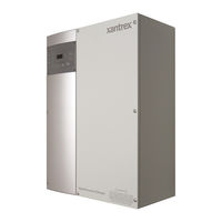
Xantrex XW6048-120/240-60 Installation Manual (136 pages)
XW Power System
Brand:
Xantrex
| Category:
Power Supply
| Size: 5.62 MB
Table of Contents
About this Guide
5
Important Safety Instructions
7
FCC Information to the User
8
Limitations on Use
8
Table of Contents
9
Introduction
17
Figure 1-1 XW Power System Installation Diagram Example
18
System Diagram
18
System Overview
18
Figure 1-2 XW Inverter/Charger
19
Figure 1-3 XW Conduit Box
19
Figure 1-4 Power Distribution Panel and XW Conduit Box
20
Figure 1-5 XW Connection Kit for INV2
21
Figure 1-7 XW System Control Panel
22
Figure 1-8 Automatic Generator Start
23
XW Automatic Generator Start
23
XW Solar Charge Controller
22
XW System Control Panel
22
Chapter 2 , “Inverter/Charger Installation” Describes How to Mount and Install
25
Conduit Box
25
Knockout Preparation
26
Location
26
Pre-Installation
26
Clearance Requirements
27
Figure 2-1 Clearance Requirements
27
Mounting
27
Figure 2-2 Mounting Plate Dimensions
28
Step 1: Installing the Mounting Plate
28
Table 2-1 Mounting Plate Fastener Recommendations
28
Figure 2-3 Mounting the Bracket for the XW Inverter/Charger or Distribution Panel
29
Figure 2-4 Mounting the XW Inverter/Charger
30
Step 2: Mounting the Inverter
30
Figure 2-5 Installing the XW Conduit Box
31
Step 3: Mounting the XW Power Distribution Panel and XW
31
Figure 2-6 Routing Communications Cables
32
Step 4: Wiring the Inverter
32
Batteries
33
Battery Bank Requirements
33
Battery Cable Requirements
33
Table 2-2 Recommended Battery Cable Size Versus Length
34
Table 2-3 Battery Cable (in Conduit) to Maximum Breaker/Fuse Size
34
Table 2-4 Torque Values for AC Wiring (AC Terminals and Ground Bar)
34
Torque Values for the XW Series Inverter/Charger
34
Table 2-10 Torque Values for the Battery Cables to the DC Negative Bus, and DC Positive Bus in the XW Power Distribution Panel
35
Table 2-7 Torque Values for AC Disconnects and AC Breakers
35
Table 2-8 Torque Values for the Ground Bus, AC Neutral Bus, DC Negative Bus, and DC Positive Bus in the XW Power Distribution Panel
35
Figure 2-7 DC Grounding Using a Power Distribution Panel
36
Grounding the DC System
36
Wiring the Inverter to the XW Power Distribution Panel
36
Figure 2-8 Battery Temperature Sensor (RJ11) Port Location and Installation
37
Installing the Battery Temperature Sensor
37
Figure 2-10 Battery Cable Connection
38
Figure 2-9 XW Inverter/Charger DC Connections
38
Making DC Connections
38
Figure 2-11 DC Connections to a Single Inverter Using a XW Power Distribution Panel
39
AC Connections and Communication Ports
40
Figure 2-12 XW Inverter/Charger AC Connections and Communications Ports
40
Making AC Connections
40
Accessing the AC Terminal Block and AC Ground Bar
41
Figure 2-13 AC Terminal Block
41
Figure 2-14 Grounding the AC System Using the Distribution Panel
42
Grounding the AC System
42
AC Wiring to the Inverter AC Distribution Panel
43
AC Wiring to the XW Power Distribution Panel
43
Figure 2-15 Wiring the XW Power Distribution Panel to the Sub-Panel or Utility Grid
44
Figure 2-16 Wiring the Inverter to the XW Power Distribution Panel
45
Wiring the XW Inverter/Charger to a XW Power Distribution Panel
45
Figure 2-17 Generator Wiring Using a XW Power Distribution Panel
46
Generator Wiring to the XW Inverter/Charger Using a XW Power Distribution Panel
46
AUX Port
47
AUX+12V Voltage Supply
47
Figure 2-18 aux Port Location
47
AUX Port Terminal Assignments
48
AUX-RPO: User Remote Power off (RPO)
48
Table 2-11 User Connector Terminals and Functions
48
User Line Wiring
48
Applying DC Power to the Inverter
49
Basic Functional Test - Single Inverter
49
Confirm All Connections
49
Figure 2-19 Power-Up Display
49
Enable the Inverter
50
Figure 2-20 Enable the Inverter
50
AC Voltage Check
51
Confirming Battery Charger Operation
51
Figure 2-21 Checking AC Voltage
51
Figure 2-22 Checking Charging Operation
51
Figure 2-23 Functional Test for Single Inverter Systems
52
Installation Steps
53
Step 5: Installing Additional Inverters
53
Converting a Single-Inverter Power Distribution Panel to a Dual-Inverter Power Distribution Panel
54
DC Wiring for a Dual-Inverter System
54
Parts List for Dual-Inverter Configurations
54
Figure 2-24 DC Connections to Dual Inverters
55
AC Wiring for a Dual-Inverter System
56
Figure 2-25 Dual Inverter AC Breaker Arrangement and Wiring Enlargement with
56
Figure 2-26 AC Wiring for Dual-Inverter Systems
57
Converting a Single-Inverter Power Distribution Panel to a Triple-Inverter Power Distribution Panel
58
DC Wiring for a Triple-Inverter System
58
Parts List for a Triple-Inverter Configuration
58
Figure 2-27 DC Connections for a Triple-Inverter System
59
AC Wiring for a Triple-Inverter System
60
Figure 2-28 Triple-Inverter AC Breaker Arrangement and Wiring Enlargement with
60
Figure 2-29 Triple-Inverter AC Breaker Arrangement and Wiring Enlargement with a
61
Figure 2-30 Wiring an External Bypass Switch for a Triple-Inverter Configuration
61
Figure 2-31 Installing the AC Sync Cable
62
Xanbus and AC Sync Cable
62
Basic Functional Test - Multiple Inverters
63
Figure 3-1 Network-Managed Power System
68
Network Components
69
Table 3-1 T568A Standard Wiring
69
Figure 3-2 Xanbus Cable and RJ45 Connector Pin Numbers
70
Figure 3-3 Network Terminators
70
Figure 3-4 3-Way Network Connector (Sample Configuration)
70
Multi-Drop Backbone Layout
71
Network Layouts
71
Ordering Network Components
71
Table 3-2 Xanbus Network Components and Part Numbers
71
Daisy Chain Layout
72
Figure 3-5 Multi-Drop Backbone Layout
72
Figure 3-6 Daisy Chain Network Layout
72
Before You Begin the Installation
73
Guidelines for Routing the Xanbus Cables
73
Installation Tools and Materials
73
Installing the Network
73
Figure 3-7 Recommended Mounting Orientation for Network Connector
74
Mounting a Network Connector
74
Table 3-3 Minimum and Maximum Cable Length
74
Completing the Multi-Drop Backbone Layout
75
Figure 3-8 Options for Completing a Multi-Drop Backbone Layout
75
Installing Xanbus-Enabled Devices
75
Completing the Daisy Chain Layout
76
Figure 3-9 Completing a Daisy-Chain Layout
76
Figure 1-6 XW Solar Charge Controller
77
Installing the Charge Controller
78
Step 3: Mounting the XW Power Distribution Panel and XW Conduit Box
31
Inverter/Charger Installation
25
System Components and Accessories
19
XW Conduit Box
19
XW Inverter/Charger
19
XW Power Distribution Panel Panel and XW Conduit Box
20
XW Connection Kit for INV2
21
For this Topic See
67
Table 2-5 Torque Values for the Chassis Ground Lug
34
Table 2-6 Torque Values for the Inverter Battery Terminals
34
Backfeed Protection Requirements
35
Inverter Grounding
35
Torque Values for the XW Power Distribution Panel
35
Xanbus Network Installation
67
The Xanbus System
68
Xanbus-Enabled Devices
68
Chapter 4 , “XW Solar Charge Controller Installation” Describes How to
78
Array Current
78
Array Size
78
Array Voltage
78
PV Array Requirements
78
Choosing a Location
79
Mounting
79
MPPT Voltage Range
79
Table 4-1 MPPT Operational Window
79
Figure 4-1 Minimum Clearance Requirements
80
Table 4-2 Minimum Clearance Requirements
80
Figure 4-2 Removing the Wiring Terminals Cover
81
Removing Knockouts
81
Removing the Wiring Terminals Cover
81
Figure 4-4 Knockout Dimensions
82
Figure 4-5 Mounting the XW Solar Charge Controller
83
Figure 4-6 XW Solar Charge Controller Safety Ground Connector
84
Grounding
84
DC Terminal Connector Locations
85
Figure 4-7 DC Connection Terminals
85
Wire Size and Over-Current Protection Requirements
85
Wiring
85
Table 4-3 Recommended Circuit Breakers for the XW Solar Charge Controller
86
Table 4-4 One-Way Wire Distance and Wire Size for a 24 VDC System
87
Table 4-5 One-Way Wire Distance and Wire Size for a 48 VDC System
87
Connecting the XW Solar Charge Controller to the Distribution Panel
88
Figure 4-8 Connecting Solar DC Sources in the Power Distribution Panel
89
Commissioning
90
Commissioning Units Using a XW System Control Panel
90
Configuration Screens
90
Figure 5-1 XW System Control Panel Xanbus Port Locations
94
Choosing a Location
95
Materials and Tools Required
95
Mounting the XW System Control Panel
95
Figure 5-2 Inserting the Mounting Plate
96
Figure 5-3 Securing the Mounting Plate
96
Figure 5-4 Connecting the Network Cables
97
Figure 5-5 Securing the XW System Control Panel
97
Figure 5-6 Surface Mounting the XW System Control Panel
98
Figure 5-7 Connecting the AGS Communications Cable to the XW Series
99
Choosing a Location
100
Routing the Connections
100
Figure 5-8 XW Automatic Generator Start External Connections
101
Installing the XW Automatic Generator Start
101
Mounting the Unit
102
Table 5-1 Circuit Limitations
102
Wiring to the 20-Contact Connector
102
Figure 5-9 XW Automatic Generator Start Wiring Harness
103
Table 5-2 Required Wiring Size Based on Length of Cable
103
Table 5-3 Contact Numbers and Functions
103
Connecting the Generator
104
Connecting an External Shutdown (Optional)
105
Connecting the Thermostats (Optional)
105
Table 5-4 Wiring for Connecting Thermostats
105
Table 5-5 Wiring for Connecting an External Shutdown
105
Connecting an External Manual ON/OFF Switch (Optional)
106
Table 5-6 Wiring for Connecting an External Manual ON/OFF Switch
106
Connecting an External ON/OFF LED
107
Figure 5-10 External On/Off Switch and LED Wiring Diagram
107
Connecting the Wiring Harness to the XW Automatic Generator Start
108
Figure 5-11 XW Automatic Generator Start External Connections
108
Connecting the XW Automatic Generator Start to the Xanbus Network
109
Figure 5-12 Connecting the SCP
109
Figure 5-13 Verifying Power Is Available
110
Verifying Power Is Available
110
Figure A-1 XW Series AC Overload Capability
113
Figure A-2 Output Power Versus Ambient Temperature
114
Inverting Efficiency (Typical
114
Output Power Versus Ambient Temperature
114
XW Series Efficiency
114
Charging Efficiency (Typical
115
Mechanical Specifications
115
Sell Mode Efficiency (Typical
115
Table A-2 XW Power System Mechanical Specifications
115
Accessories
116
Figure B-1 Single-Inverter System (Backup Only
119
Figure B-2 Single-Inverter System Renewable Energy (Solar
120
Single-Inverter System Renewable Energy (Solar
120
Figure B-3 Single-Inverter System Renewable Energy (Wind or Hydro
121
Single-Inverter System Renewable Energy (Wind or Hydro
121
Dual-Inverter System Renewable Energy (Solar
122
Figure B-4 Dual-Inverter System Renewable Energy (Solar
122
Dual-Inverter System Renewable Energy (Wind or Hydro
123
Figure B-5 Dual-Inverter System Renewable Energy (Wind or Hydro
123
Figure C-1 DC Grounding for an Inverter Only
126
Battery Connections for Single Inverter Systems
127
Figure C-2 DC Connections to a Single Inverter
127
AC Grounding for Single-Inverter Systems
128
Figure C-3 Grounding the AC System
128
AC Output Wiring to the Inverter AC Distribution Panel
129
Figure C-4 AC Output Wiring to the Inverter AC Distribution Panel
129
Figure C-5 Generator Wiring Directly to the Inverter
130
Generator Wiring to the Inverter
130
Figure C-6 Utility Wiring to the Inverter Input
131
Utility Wiring to the Inverter Input
131
Wind or Hydro DC Sources
132
Figure 4-3 Dimensions and Knockout Locations
81
Mounting the Controller
82
XW Solar Charge Controller Installation
78
XW System Accessories Installation
93
The XW System Control Panel
94
Appendix A Specifications
111
Electrical Specifications
112
Table A-1 XW Power System Electrical Specifications
112
XW Series Overload Capability
113
Appendix B Wiring Diagrams
117
Single-Inverter System (Backup Only
117
Appendix C Alternate System Configurations
125
Materials and Tools Required
99
Preparing an Installation
99
The XW Automatic Generator Start
99
Verifying the Installation
99
DC Grounding for Single-Inverter Systems
126
Figure C-7 Connecting Wind or Hydro DC Sources
132
Advertisement
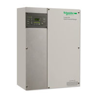
Xantrex XW6048-120/240-60 Operation Manual (112 pages)
XW Series Hybrid Inverter/Charger
Brand:
Xantrex
| Category:
Inverter
| Size: 1.05 MB
Table of Contents
About this Guide
5
Conventions Used
6
Important Safety Instructions
7
Explosive Gas Precautions
8
Precautions When Working with Batteries
8
Table of Contents
11
1 Introduction
15
Basic Features
16
Basic Operation
17
Surge Performance
18
Islanding Protection
19
Monitoring the Inverter
20
Inverter Information Panel
20
XW System Control Panel
21
2 Monitoring Operation
23
Monitoring Operation with the Inverter Information Panel
24
Monitoring AC Input Status
24
Monitoring Inverter Status
25
Monitoring Charger Status
25
Monitoring Faults and Warnings
25
Equalizing Batteries
26
Turning the XW Inverter/Charger on and off
27
Monitoring Battery Level
28
Reading the Display Screen
28
Monitoring Operation with the XW System Control Panel
29
XW System Control Panel Features
29
Using the Standby Button
30
System Control Panel Navigation
30
Viewing the System Control Panel Home Screens
30
Viewing Other Screens
32
Reading the System Status Screen
33
Reading the XW Inverter/Charger Home Screen
33
Reading the Meters Screen
36
3 Configuration
39
Using the XW System Control Panel
40
XW Inverter/Charger Setup Menu
40
Setting the Time and Date
41
Using the Setup Menus
42
Fault Messages
45
Inverter Settings Menu
45
Using the Low Battery Cut out and LBCO Delay Settings
45
Using Search Mode
46
Charger Settings Menu
48
Battery Charger Functions
49
Multi-Stage Charging Process
49
Equalize Charging the Batteries
51
Using Charger Block
52
Custom Battery Settings Menu
53
AC Settings
54
Grid Support Settings
55
Energy Management
56
Charger Block
56
Grid Support
56
Peak Load Shaving
57
Time-Of-Use Metering
57
Generator Support Settings
59
Auxiliary Output Settings
59
Trigger Source Descriptions
60
Multi-Unit Config Menu
61
Setting the Device Name
62
Setting the Device Number
63
Connections Menu
64
Operating Without Connections
65
Copying Settings from Another Unit
66
Resetting the XW Inverter/Charger to Default Settings
66
4 Troubleshooting
67
Troubleshooting Reference
68
General Troubleshooting Guidelines
68
Inverter Applications
69
Resistive Loads
69
Motor Loads
69
Problem Loads
70
Clocks
70
Fluorescent Lights and Power Supplies
70
Searching
70
Very Small Loads
70
Inverter Troubleshooting
71
Battery Charger Troubleshooting
74
Faults and Warnings
76
Warning Messages
76
Warning Types
77
Fault Messages
81
Fault Types
82
Inverter Operation after Faults
82
Specifications
93
Electrical Specifications
94
XW Inverter/Charger Overload Capability
95
Inverting Efficiency (Typical
96
Output Power Versus Ambient Temperature
96
XW Inverter/Charger Efficiency
96
Charging Efficiency (Typical
97
Sell Mode Efficiency (Typical
97
Mechanical Specifications
97
Accessories
98
B Default Settings
99
Default Settings and Ranges
100
Inverter Menu
101
Charger Menu
101
Custom Battery Menu
102
AC Menu
102
Grid Support Menu
103
Gen Support Menu
103
Aux Menu
104
Connections Menu
104
Warranty and Return Information
105
Return Material Authorization Policy
107
Return Procedure
107
Out of Warranty Service
107
Information about Your System
108
Index
109
Advertisement
Related Products
Xantrex XW4024-120/240-60, XW4548-120/240-60, XW6048-120/240-60
Xantrex XW4548-120/240-60
Xantrex XDC 6000
Xantrex XMP 2600
Xantrex XTR 20-42
Xantrex XDL 56-4P
Xantrex XTR 850 Watt Series
Xantrex XKW 12-150
Xantrex XT 60-1
Xantrex XFR 35-35
Xantrex Categories
Inverter
Power Supply
Battery Charger
Power Pack
Controller
More Xantrex Manuals
Login
Sign In
OR
Sign in with Facebook
Sign in with Google
Upload manual
Upload from disk
Upload from URL