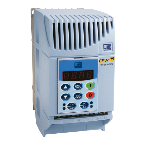
Sign In
Upload
Manuals
Brands
WEG Manuals
Inverter
CFW08 Vector inverter
WEG CFW08 Vector inverter Manuals
Manuals and User Guides for WEG CFW08 Vector inverter. We have
1
WEG CFW08 Vector inverter manual available for free PDF download: User Manual
WEG CFW08 Vector inverter User Manual (167 pages)
Vector Frecuency Inverter
Brand:
WEG
| Category:
Inverter
| Size: 1.76 MB
Table of Contents
Table of Contents
4
Parameters
8
Quick Parameter Reference
8
Fault Messages
15
Other Messages
15
Chapter 1
16
Safety Notices in the Manual
16
Safety Notice on the Product
16
Preliminary Recommendations
16
About this Manual
18
Version of Software
18
General Information
18
About the CFW-08
19
CHAPTER 2 Differences between the Old Μline and the New CFW-08
22
Identification
26
Receiving and Storing
28
Mechanical Installation
29
Chapter 3
29
Environment
29
Mounting Specifications
30
Installation and Connection
30
Electrical Installation
33
Power/Grounding Connections
33
Power Terminals
36
Location of the Power/Grounding/Control Connections
37
Control Wiring
38
Typical Terminal Connections
41
European EMC Directive
44
Installation
44
Inverter Models and Filters
45
EMC Categories Description
47
EMC Categories Characteristics Filters
48
Pre-Power Checks
53
Initial Power-Up
53
Start-Up
54
Start-Up Operation Via Keypad (HMI) Type of Control: Linear V/F (P202=0)
54
Start-Up Operation Via Terminals
56
CHAPTER 4 Type of Control: Linear V/F (P202=0)
56
Start-Up - Operation Via Keypad (HMI) Type of Control: Vector (P202=2)
57
Keypad (HMI) Description
61
Use of the Keypad Hmi
62
Keypad Operation
63
Inverter Status
64
Read-Only Variables
64
Parameter Viewing and Programming
65
CHAPTER 5 Detailed Parameter Description
67
Symbols
67
Introduction
67
Control Modes
67
V/F Control
67
Vector Control (VVC)
68
Frequency Reference Sources
68
Commands
71
Local/Remote Operation Modes
71
Parameter Listing
72
Access and Read Only Parameters - P000
73
Access/Read Only Parameters
73
Regulation Parameters - P100
74
Configuration Parameters - P200
82
Motor Parameters - P399
102
Special Function Paramaters - P500
105
PID Introduction
105
PÌD Description
105
PID Start-Up Guide
107
CHAPTER 7 Diagnostics and Troubleshooting
111
Faults and Possible Causes
111
Troubleshooting
113
Contacting weg
114
Preventive Maintenance
114
Cleaning Instructions
115
CHAPTER 8 Options and Accessories
117
Hmi-Cfw08-P
117
Instructions for Insertion - Removing of HMI-CFW08-P
118
Tcl-Cfw08
118
Hmi-Cfw08-Rp
118
HMI-CFW08-RP Installation
119
Mip-Cfw08-Rp
119
Cab-Rp-10
120
Hmi-Cfw08-Rs
120
HMI-CFW08-RS Installation
121
HMI-CFW08-RS Start-Up
121
Keypad Copy Function
122
Mis-Cfw08-Rs
122
Cab-Rs-10
122
Kcs-Cfw08
123
Instruction and Removing Instructions for KCS-CFW08
124
Ksd-Cfw08
124
Kmd-Cfw08-M1
125
Kfix-Cfw08-M1, Kfix-Cfw08-M2
126
Kn1-Cfw08-M1, Kn1-Cfw08-M2
127
126
127
RFI Filters
128
Line Reactor
129
Application Criteria
129
Load Reactor
131
Dynamic Braking
132
Resistor Sizing
132
Installation
133
Serial Communication
134
Introduction
134
Interfaces Description
135
134
135
136
137
Definitions
137
Character Format
137
Parameters/Variables Resolution
137
Used Terms
137
Protocol
138
Reading Message
138
Execution and Message Test
139
Writing Message
139
Message Sequence
140
Varaiables Code
140
Message Examples
140
Variables and Errors of the Serial Communication
141
Basic Variables
141
V00 (Code 00700)
141
V02 (Code 00702)
141
V03 (Code 00703)
142
Message Examples with Basic Variables
143
V04 (Code 00704)
143
V05 (Code 00705)
143
Errors Related to the Serial Communication
145
Times for Read/Write of Messages
145
Physical Connection of RS-232 and RS-485 Interface
146
Modbus-RTU
147
Introduction in the Modbus-RTU Protocol
147
Message Structure in RTU Mode
147
Transmission Modes
147
Address
148
Code Function
148
Crc
148
Data Field
148
Time between Messages
149
Operation of the CFW-08 in the Modbus-RTU Network
149
Interface Description
149
149
150
Access to the Inverter Data
150
Inverter Address in the Network
150
Inverter Configuration in the Modbus-RTU Network
150
Transmission Rate and Parity
150
3.1Available Functions and Response Times
151
Register Addressing and Offset
151
Detailed Function Description
153
Function 01 - Read Coils
154
Function 03 - Read Holding Register
154
Function 05 - Write Single Coil
155
Function 06 - Write Single Register
156
Function 15 - Write Multiple Coils
156
Function 16 - Write Multiple Registers
157
Function 43 - Read Device Identification
158
Communication Errors
160
Error Messages
160
CHAPTER 9 Technical Specifications
162
Power Data
162
240V Power Supply
162
General Electronic Data
164
WEG Standard IV Pole Motor Data
165
Advertisement
Advertisement
Related Products
WEG CFW-09
WEG CFW08 Vector inverter Plus
WEG bacnet CFW701
WEG DeviceNet CFW500
weg CFW501 V1.8X
WEG CFW11W G2 2223 T 6
WEG CFW11W G2 2964 T 6
WEG CFW11W G2 3705 T 6
WEG CFW100-KHMIR
WEG CFW11M G2 1807 T 4 O RB
WEG Categories
DC Drives
Controller
Circuit breakers
Control Unit
Inverter
More WEG Manuals
Login
Sign In
OR
Sign in with Facebook
Sign in with Google
Upload manual
Upload from disk
Upload from URL