Sign In
Upload
Manuals
Brands
Webasto Manuals
Battery Charger
ProCore Edge 9
Webasto ProCore Edge 9 Manuals
Manuals and User Guides for Webasto ProCore Edge 9. We have
2
Webasto ProCore Edge 9 manuals available for free PDF download: Installation, Operation And Maintenance Manual
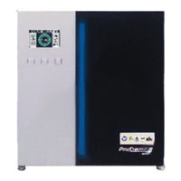
Webasto ProCore Edge 9 Installation, Operation And Maintenance Manual (136 pages)
Brand:
Webasto
| Category:
Battery Charger
| Size: 4 MB
Table of Contents
English
4
Table of Contents
4
Installation, Operation and Maintenance Manual
6
Scope
6
Acronyms, Abbreviations and Symbols
7
Required Tools
9
Technical Specifications for 48V and 80V Modules Fitted with 3- or 5-Bay Cabinets
9
Installation
11
Multi-Charger Installation Schemes
11
Installation Precautions
13
Positioning the Charger
14
Wall-Mount Installation
15
Floor Stand Installation
16
Ten-Way Screw Terminal Connector
31
Remote Battery Connections (Option)
31
Optional Features
34
Putting Back the DC-Panel and Top Covers
34
DC-Panel Cover
34
Top Cover
34
Charger Light Bar
35
Operating Instructions
37
Battery Display
39
Buttons
44
Maintenance
46
Power Module Replacement
46
Air Filter Replacement (TBA - Not yet Available)
57
Preventive Maintenance Activities
57
Faults and Warnings
60
Español
72
Alcance
74
Manual de Instalación, Operación y Mantenimiento
74
Siglas, Abreviaturas y Símbolos
75
Especificaciones Técnicas para Módulos de 48 V y 80 V Equipados con Gabinetes de 3 O 5 Bahías
77
Herramientas Necesarias
77
Esquemas de Instalación de Varios Cargadores
79
Instalación
79
Precauciones de Instalación
81
Posicionamiento del Cargador
82
Instalación de Montaje en Pared
83
Instalación del Soporte de Piso
84
Conector de Terminal de Tornillo de Diez Vías
99
Conexiones de la Batería Remota (Opcional)
99
Tabla 1 Conexiones de Señal de Extremo Expuesto
101
Características Opcionales
102
Cubierta del Panel de CC
102
Cubierta Superior
102
Reinstalación del Panel de CC y las Cubiertas Superiores
102
Barra de Luz del Cargador
103
Instrucciones de Operación
105
Pantalla de Batería
107
Botones
112
Mantenimiento
114
Reemplazo del Módulo de Energía
114
Actividades de Mantenimiento Preventivo
125
Reemplazo del Filtro de Aire (Aún no Disponible)
125
Tabla 2 Programa de Mantenimiento Preventivo
126
Fallas y Advertencias
128
Advertisement
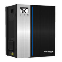
Webasto ProCore Edge 9 Installation, Operation And Maintenance Manual (76 pages)
Brand:
Webasto
| Category:
Battery Charger
| Size: 3 MB
Table of Contents
Table of Contents
4
Installation, Operation, and Maintenance Manual
9
Scope
9
Acronyms, Abbreviations, and Symbols
10
Required Tools
13
Technical Specifications for 48- and 80-Volt Modules Fitted with Three- or Five-Bay Cabinets
13
Installation
15
Multicharger Installation Schemes
15
Figure 1 Side-To-Side Airflow Design, Top View
15
Figure 2 Standard Side-To-Side Charger Spacing
15
Figure 3 Side-To-Side Charger Spacing with Dividers
16
Figure 4 Offset 45-Degree Angle Charger Installation
16
Installation Precautions
17
Positioning the Charger
18
Figure 5 Attaching Points for M8 Lifting Eye-Bolts
18
Wall-Mount Installation
19
Figure 6 Charger, Wall, Wall-Mount Hanger, Bottom Bracket, and Screw with an M6 Thread
19
Figure 7 Charger on the Wall-Mount Hanger
19
Figure 8 Bottom Bracket Mounted to the Charger with a Tightening Torque of 52.22 In.-Lb. (5.9 N-M)
19
Floor-Stand Installation
20
Figure 9 Floor Stand
20
Figure 10 Predrilled Holes for Bolting the Base to the Floor
21
Figure 11 Pogo Stick (Optional) Attached to the Pogo Bracket
21
Figure 12 Charger Hung on the Floor Stand
22
Figure 13 Bottom Bracket Mounted to the Charger and
23
AC Power Connection
24
Figure 14 Six M6 Panel Crews, Top-Panel View
25
Figure 15 AC Service Entrance
26
Figure 16 AC Service Entrance for the Three-Bay Cabinet
27
Figure 17 AC Service Entrance for the Five-Bay Cabinet
28
DC Battery Connection
29
Figure 18 Two TORX TX25 Screws Securing the DC Output Power Cable Panel
32
Figure 19 Three- and Five-Bay Bus Bar Arrangement
33
Remote Battery Connections (Option)
35
Ten-Way Screw Terminal Connector
35
Figure 20 Ten-Way Screw Terminal Connector
35
Figure 21 Battery Communication Wires Connected to the Screw Terminal
36
Table 1 Bare-Ended Signal Connections
37
Optional Features
38
Putting Back the DC-Panel and Top Covers
38
DC-Panel Cover
38
Top Cover
38
Charger Light Bar
39
Operating Instructions
41
Figure 22 Charger Display
41
Battery Display
43
Figure 23 Graphical Battery Display
43
Figure 24 Alternate Tabular Battery Display
48
Buttons
49
Maintenance
51
Power Module Replacement
51
Figure 25 Latch on the Side of the Charger
51
Figure 26 Disconnected Power Cables
52
Figure 27 Ground Cable Disconnection
53
Figure 28 Single-Cable Connection
54
Figure 29 Multicable Connection
55
Figure 30 Power Module Removal
56
Figure 31 Replacement Power Module Insertion
57
Figure 32 Power Module Position Selector
58
Figure 33 Power Module Positions
58
Figure 34 Flat Cable Reconnection to the Power Module
59
Figure 35 Flat Cable Connection to the Termination Block
60
Air Filter Replacement
61
Preventive Maintenance Activities
61
Figure 36 Reconnected DC Output Power Cable
61
Figure 37 Reconnected Ground Cable and AC Input Power Cable
61
Table 2 Preventive Maintenance Schedule
62
Faults and Warnings
64
Advertisement
Related Products
Webasto ProCore Edge 15
Webasto ProCore Edge
Webasto Air Top Evo 5500 Series
Webasto Air Top Evo 55D
Webasto Air Top Evo 40D
Webasto Air Top Evo 55B
Webasto Dual Top Evo 6
Webasto Air Top Evo 5500 B
Webasto Thermo Top Evo 5+
Webasto Air Top Evo 40 B
Webasto Categories
Heater
Water Heater
Automobile Accessories
Air Conditioner
Battery Charger
More Webasto Manuals
Login
Sign In
OR
Sign in with Facebook
Sign in with Google
Upload manual
Upload from disk
Upload from URL