Sign In
Upload
Manuals
Brands
WAGO Manuals
I/O Systems
750-626/040-000
WAGO 750-626/040-000 Manuals
Manuals and User Guides for WAGO 750-626/040-000. We have
2
WAGO 750-626/040-000 manuals available for free PDF download: Manual
WAGO 750-626/040-000 Manual (56 pages)
Design Notes /XTR Guidelines and Recommendations for Increasing Operational Safety
Brand:
WAGO
| Category:
I/O Systems
| Size: 2.95 MB
Table of Contents
Deutsch
3
Table of Contents
3
1 Notes about this Documentation
5
Validity of this Documentation
5
Copyright
5
Symbols
6
Number Notation
8
Font Conventions
8
Table 1: Number Notation
8
Table 2: Font Conventions
8
2 Important Notes
9
Legal Bases
9
Subject to Changes
9
Personnel Qualifications
9
Use of the WAGO-I/O-SYSTEM 750 in Compliance with Underlying Provisions
9
Technical Condition of Specified Devices
10
Safety Advice (Precautions)
11
3 System Description
13
Manufacturing Number
15
Component Update
16
Storage, Assembly and Transport
16
Assembly Guidelines/Standards
16
Technical Data
17
Mechanics
17
Electrical Safety
17
Table 3: Technical Data - Mechanics
17
Table 4: Technical Data - Electrical Safety
17
Connection Type
18
Climatic Environmental Conditions
18
Table 5: Technical Data - Field Wiring
18
Table 6: Technical Data - Power Jumper Contacts
18
Table 7: Technical Data - Internal Bus
18
Table 8: Technical Data - Climatic Environmental Conditions
18
Residential Use
19
Example Dimensions
20
4 Standards and Approvals
21
Table 9: Climatic and Mechanical Environmental Conditions
21
Table 10: EMC
22
5 Assembly
23
Mounting Position
23
Overall Configuration
23
Mounting Onto Carrier Rail
24
Carrier Rail Properties
24
WAGO DIN Rail
25
Table 11: WAGO DIN Rail
25
Table 12: Permissible WAGO Carrier Rails When Using XTR PFC200
25
Spacing
26
Mounting Sequence
27
Inserting and Removing Devices
29
Inserting the Fieldbus Coupler/Controller
29
Removing the Fieldbus Coupler/Controller
29
Inserting the I/O Module
30
Removing the I/O Module
31
6 Connect Devices
32
Data Contacts/Internal Bus
32
Power Contacts/Field Supply
33
Connecting a Conductor to the CAGE CLAMP
34
Connecting a Conductor to the Push-In CAGE CLAMP
35
Power Supply
36
Isolation
36
System Supply
37
Connection
37
Table 13: Legend for Figure "System Voltage for Fieldbus Couplers
37
Dimensioning
38
Table 14: Alignment
38
Field Supply
41
Connection
41
Table 15: Legend for Figure "Field Supply for Fieldbus Couplers/Controllers
41
Fusing
42
Power Supply for Mixed Operation
44
Table 16: XTR Supply Modules for Powering XTR Sections
44
Supplementary Power Supply Regulations
45
Table 17: Filter Modules for 24 V Power Supply
45
Supply Example
47
Table 18: Legend for Figure "Power Supply Example
48
Power Supply Units
49
Table 19: WAGO Power Supply Units
49
Grounding
50
Grounding the DIN Rail
50
Framework Assembly
50
Insulated Assembly
50
Table 20: WAGO Ground Wire Terminals
50
Grounding Function
51
Shielding
52
General
52
Bus Cables
52
Signal Lines
53
WAGO Shield Connecting System
53
English
54
Figure 1: Fieldbus Node (Example)
13
Figure 2: Marking Area for Serial Numbers
15
Figure 3: Dimensions - Nodes with Fieldbus Coupler/Controller (Example)
20
Figure 4: Spacing
26
Figure 5: Release Tab Standard Fieldbus Coupler/Controller (Example)
29
Figure 6: Insert I/O Module (Example)
30
Figure 7: Snap the I/O Module into Place (Example)
30
Figure 8: Removing the I/O Module (Example)
31
Figure 9: Data Contacts
32
Figure 10: Example for the Arrangement of Power Contacts
33
Figure 11: Connecting a Conductor to a CAGE CLAMP
34
Figure 12: Connecting a Conductor to a Push-In CAGE CLAMP
35
Figure 13: Isolation for Fieldbus Couplers/Controllers (Example)
36
Figure 14: System Voltage for Fieldbus Couplers/Controllers (Example)
37
Figure 15: System Supply for Fieldbus Coupler/Controller
38
Figure 16: Field Supply for Fieldbus Couplers/Controllers (Example)
41
Figure 17: Fuse Modules for Automotive Fuses, Series 282
42
Figure 18: Fuse Modules for Automotive Fuses, Series 2006
42
Figure 19: Fuse Modules with Pivotable Fuse Carrier, Series 281
43
Figure 20: Fuse Modules with Pivotable Fuse Carrier, Series 2002
43
Figure 21: Power Supply Concept
45
Figure 22: Power Supply Example
47
Figure 23: Carrier Rail Contact (Example)
51
Figure 24: Cable Shield at Ground Potential
52
Figure 25: Examples of the WAGO Shield Connecting System
53
Figure 26: Application of the WAGO Shield Connecting System
53
List of Figures
54
List of Tables
55
Advertisement
WAGO 750-626/040-000 Manual (54 pages)
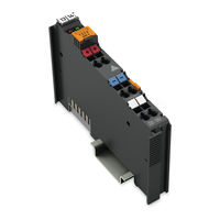
Power Supply 24 VDC Fuse XTR, Power Supply, 24 VDC, Fuse Holder, Extreme for WAGO I/O SYSTEM 750 XTR
Brand:
WAGO
| Category:
Power Supply
| Size: 1.92 MB
Table of Contents
Table of Contents
3
1 Notes about this Documentation
5
Validity of this Documentation
5
Copyright
5
Symbols
6
Number Notation
8
Font Conventions
8
Table 1: Number Notation
8
Table 2: Font Conventions
8
2 Important Notes
9
Legal Bases
9
Subject to Changes
9
Personnel Qualifications
9
Use of the 750 Series in Compliance with Underlying Provisions
9
Technical Condition of Specified Devices
10
Disposal
10
2.1.4.1.1 Electrical and Electronic Equipment
10
2.1.4.1.2 Packaging
11
Safety Advice (Precautions)
12
3 Device Description
15
View
17
Figure 1: View
17
Table 3: Legend for Figure "View
17
Connectors
18
Data Contacts/Local Bus
18
Figure 2: Data Contacts
18
Power Jumper Contacts/Field Supply
19
Figure 3: Power Jumper Contacts
19
Table 4: Legend for Figure "Power Jumper Contacts
19
Cage Clamp
20
Connectors
20
Figure 4: CAGE CLAMP
20
Table 5: Legend for Figure "CAGE CLAMP
20
Display Elements
21
Operating Elements
21
Figure 5: Display Elements
21
Table 6: Legend for Figure "Display Elements
21
Table 7: Display Elements - States
21
Schematic Diagram
22
Figure 6: Schematic Diagram
22
Technical Data
23
Device Data
23
Supply
23
Connection Type
23
Table 8: Technical Data - Device
23
Table 9: Technical Data - Supply
23
Table 10: Technical Data - Field Wiring
23
Table 11: Technical Data - Power Jumper Contacts
23
Mechanical Conditions
24
Climatic Environmental Conditions
24
Table 12: Technical Data - Data Contacts
24
Table 13: Technical Data - Mechanical Conditions
24
Table 14: Technical Data - Climatic Environmental Conditions
24
Approvals
25
Standards and Guidelines
26
Table 15: Standards and Rated Conditions for Explosion Protection Applications
26
Table 16: Climatic and Mechanical Environmental Conditions and Shipbuilding
27
Table 17: EMC - Immunity to Interference
28
Table 18: EMC - Emission of Interference
30
Table 19: Standards and Rated Conditions for Rail Applications (en 50155)
31
4 Mounting
32
Mounting Sequence
32
Inserting and Removing Devices
33
Inserting the I/O Module
33
Figure 7: Insert I/O Module (Example)
33
Figure 8: Snap the I/O Module into Place (Example)
34
Removing the I/O Module
35
Figure 9: Removing the I/O Module (Example)
35
5 Connect Devices
36
Connecting a Conductor to the CAGE CLAMP
36
Figure 10: Connecting a Conductor to a CAGE CLAMP
36
Power Supply Concept
37
Supplementary Power Supply Regulations
37
Figure 11: Supply Concept
37
Power Supply Units
38
6 Startup and Service
39
Fuse Installation or Replacement
39
Figure 12: Removing the Fuse Holder
39
Figure 13: Opening the Fuse Holder
40
Figure 14: Replacing the Fuse
40
7 Use in Hazardous Environments
41
Marking Configuration Examples
42
Marking for Europe According to ATEX and Iecex
42
Figure 15: Marking Example According to ATEX and Iecex
42
Figure 16: Text Detail - Marking Example According to ATEX and Iecex
42
Table 20: Description of Marking Example According to ATEX and Iecex
43
Figure 17: Marking Example for Approved Ex I I/O Module According to ATEX and Iecex
44
Figure 18: Text Detail - Marking Example for Approved Ex I I/O Module According to ATEX and Iecex
44
Table 21: Description of Marking Example for Approved Ex I I/O Module According to ATEX and Iecex
45
Marking for the United States of America (NEC) and Canada (CEC)
46
Figure 19: Marking Example According to NEC
46
Figure 20: Text Detail - Marking Example According to NEC 500
46
Table 22: Description of Marking Example According to NEC 500
46
Figure 21: Text Detail - Marking Example for Approved
47
Figure 22: Text Detail - Marking Example for Approved
47
Table 23: Description of Marking Example for Approved
47
Table 24: Description of Marking Example for Approved
47
Figure 23: Text Detail - Marking Example for Approved
48
Table 25: Description of Marking Example for Approved
48
Installation Regulations
49
Special Notes Including Explosion Protection
49
Special Notes Regarding ANSI/ISA Ex
51
List of Figures
52
List of Tables
53
Advertisement
Related Products
WAGO 750-626/xxx-xxx
WAGO 750-624/040-001
WAGO 750-636
WAGO 750-650/000-009
WAGO 750-650/000-015
WAGO 750-650/003-000
WAGO I/O-SYSTEM 750-613
WAGO 750-655
WAGO 750-630/000-002
WAGO 750-630/000-006
WAGO Categories
I/O Systems
Control Unit
Power Supply
Switch
Controller
More WAGO Manuals
Login
Sign In
OR
Sign in with Facebook
Sign in with Google
Upload manual
Upload from disk
Upload from URL