Tektronix AWG5000B Series Manuals
Manuals and User Guides for Tektronix AWG5000B Series. We have 2 Tektronix AWG5000B Series manuals available for free PDF download: Service Manual, Quick Start Manual

Tektronix AWG5000B Series Service Manual (154 pages)
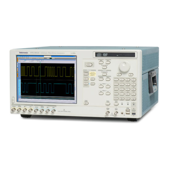
Arbitrary Waveform Generators
Brand: Tektronix
|
Category: Portable Generator
|
Size: 9 MB
Table of Contents
Advertisement
Tektronix AWG5000B Series Quick Start Manual (104 pages)
AWG5000 Series and AWG7000 Series Arbitrary Waveform Generators
Brand: Tektronix
|
Category: Portable Generator
|
Size: 7 MB