Sign In
Upload
Manuals
Brands
Tektronix Manuals
Amplifier
11A52
Tektronix 11A52 Manuals
Manuals and User Guides for Tektronix 11A52. We have
4
Tektronix 11A52 manuals available for free PDF download: Service Manual, Service & Reference Manual, User Reference Supplement, Manual
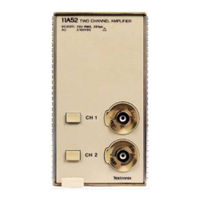
Tektronix 11A52 Service Manual (128 pages)
Extended Service, Two Channel Amplifier
Brand:
Tektronix
| Category:
Amplifier
| Size: 14 MB
Table of Contents
Table of Contents
5
List of Illustrations
9
Safety Summary
11
Section 1- General Information
15
Introduction
15
Amplifier-To-Oscilloscope Compatibility
15
Initial Inspection
15
Oscilloscope Options
17
Packaging for Shipment
17
Operating Temperature
17
Section 2-Theory of Operation
21
Block Diagram
21
Figure 2-1 11A52 Basic Block Diagram
23
Input Attenuators
24
Attenuators
24
AC/DC Coupling (#2 Relay)
24
Calibrate/Normal (#1 Relay)
24
Lox/Lx (#3 Relay)
25
Lox/Lx (#4 Relay)
25
Attenuator States
25
Off
25
Calibration
26
Input Overload Sensing
26
Fuse Check Circuit
26
Relay Fast Power on (RFPO)
26
Kernel
27
Analog Control Voltage System
27
Analog-To-Digital Converter
28
Random Access Memory
29
Data Retention Mode
29
Read Mode
29
Write Mode
29
Calipration Buff er Amplifier
29
Mpv
30
Oscillator
31
Housekeeper IC
31
Digital-To-Analog Converter
33
Address Buffer Latch
33
Output Latches
34
Reset Circuit
34
Analog Control/Signal Amplifiers
34
Sample/Hold Assemblies
34
Coarse and Fine Offsets
35
High Frequency Adjust Signals
35
Signal Amplifiers
36
Power Supplies
37
Section 3 -Maintenance
39
Preventive Maintenance
41
Amplifier Shield Removal
41
Cleaning
41
Exterior
42
Interior
42
Visual Inspection
42
Semiconductor Checks
42
Periodic Electrical Adjustment
43
Corrective Maintenance
43
Ordering Parts
43
Static-Sensitive Device Classification
44
Replacing Parts
45
How to Replace Semiconductors
45
How to Remove the Housekeeper Integrated Circuit
45
How to Install the Housekeeper Integrated Circuit
46
How to Replace Amplifier Hybrid Circuits
46
Figure 3-1 Exploded View of Housekeeper IC
46
How to Replace Peltola Coaxial-Cable Connectors
50
Figure 3-3 Peltola Coaxial Cable Connector Assembly
50
How to Remove the Front Panel
51
How to Install the Front Panel O
51
How to Replace a Front Panel Board
51
How to Remove the Main Board
52
Figure 3-4 Nut Blocks and Heat Sink Retaining Screws
52
How to Install the Main Board
53
Figure 3-5 How the Main Board Fits in the Frame
53
How to Remove and Replace a BNC Connector Assembly (BCA)
54
How to Remove an Attenuator Assembly (AA)
54
How to Install an Attenuator Assembly (AA)
54
Soldering Techniques
55
Figure 3-6 Recommended Desoldering Sequence
56
Troubleshooting
57
Troubleshooting Aids
57
Diagrams
57
Circuit Board Illustrations
57
Component Color Coding
57
Wiring Color Code
58
Semiconductor Lead Configurations
58
Figure 3-7 Resistor Color Codes
58
Figure 3-8 Semiconductor Lead Configurations
59
Multi-Pin Connector Identification
60
Figure 3-9 Multi-Pin Connector Orientation
60
Troubleshooting Equipment
61
Troubleshooting Techniques
62
Check Control Settings
62
Check Associated Equipment
62
Visual Check
62
Isolate Trouble to Circuit
62
Check Oscilloscope Adjustment
63
Check Individual Components
63
Repair and Adjust the Circuit
64
Section 4-Diagnostics
65
Diagnostics Overview
67
Kernel Tests
67
Figure 4-1 Sample LED Fault Code Timing Diagram
68
Self Tests
70
Extended Diagnostics
71
Test Descriptions
72
Attenuator-Driver Test (RELAY DRVR)
72
Check Probecode Stability (PROBECODES)
73
Check Signal Path Calconstant Checksum (CKSM PLUG)
73
Check Probe Calconstant Checksum (CKSM PROBE)
74
Walking Ones Test (WALK ONES)
74
Analog-To~Digital Converter Test (ADC TEST)
75
Fuse Test (FUSE TEST)
75
Analog Control Voltage System Test (ACVS TEST)
75
Calconstant Diagnostics
77
Probe Gain
78
Attengain
79
Bwlmatch
79
Gain
79
Step Gain
79
Balance
80
Coarse Dac
80
Outputerr
80
Fine Dac
81
Prb Coarse
81
Prb Fine
81
Spare Gain
81
Bias Comp
82
Bias Error
82
Prbimbal
82
Explain Cal (EXPLAINCAL)
83
Attengain
86
Bwlmatch
86
Step Gain
86
Calconstant Dumper (CC DUMPER)
87
Gain
87
Gainoff
88
Gainon
88
Unreported Amplifier Calibration Failures
88
Trigger Path Failure
89
Large Amplifier Errors
89
Old Calibration Constants
89
Failures Reported Though Calibration Achieved
89
CKSM Plug Failure at Power-Up
90
Advertisement
Tektronix 11A52 Service & Reference Manual (90 pages)
Brand:
Tektronix
| Category:
Amplifier
| Size: 4 MB
Table of Contents
Table of Contents
5
List of Illustrations
7
List of Tables
8
Safety Summary
9
In this Manual
9
Section 1- General Information
11
Introduction
11
I I I
12
Plug-In to Mainframe Compatibility
12
Initial Inspection
12
Installing and Removing the Plug-In
12
Instrument Options
13
Packaging for Shipment
13
Figure 1-1 Installing a Plug-In in a Mainframe Oscilloscope
13
Operating Environment
14
Operating Temperature
14
Section 2 - Checks and Adjustments
15
Using this Procedure
15
Menu Selections and Measurement Techniques
15
Plug-In Installation and Removal
16
Initialized Setting
16
Test Equipment
16
Procedure Parts
16
Part 1- Initial Setup
19
Measurement Limits
20
Specifications
20
Part 2A-Check!Examine/Adjust High Frequency Response: Standard Procedure
21
Examine Mainframe High Frequency Response
21
Examine/Adjust Plug-In Step Response
23
I I I
25
Check Plug-In Bandwidth
27
Part 2B-Check/Examine/Adjust High Frequency Response: Alternative Procedure
29
Examine Mainframe High Frequency Response
30
Examine/Adjust Plug-In Step Response
31
Check Plug-In Bandwidth
35
Part 3-Check Enhanced Accuracy
37
Part 4-Check DC Balance
39
I I I
41
Part 5B-Check
41
Part 6-Check DC
45
Characterize 11301/11302 Mainframe
45
Section 3 - Maintenance
54
Preventive Maintenance
54
Plug-In Shield Removal
54
Cleaning
55
Visual Inspection
55
Periodic Electrical Adjustment
55
Corrective Maintenance
56
Ordering Parts
56
Static-Sensitive Device Classification
56
Removing and Replacing Frus
58
Semiconductor FRU Removal
60
Housekeeper Integrated Circuit ("Slam-Pack" IC)
60
Figure 3-2 Semiconductor Indexing Diagram
61
Figure 3-3 Hypcon Assembly Removal and Replacement
63
Ram IC
65
Eprom IC
65
Processor IC
66
Circuit Board and Attenuator FRU Removal
67
Coaxial Cables
69
Figure 3-5 Location of the Screws and Parts for Removal of an Attenuator
69
Figure 3-6 Location of a Nut Block Securing the Circuit Board to the Frame Section
70
Programming the Unit Identification
71
Cables and Connectors
72
BNC Connectors
72
Multi-Pin Connectors
73
Arrangement of Pins in a Multi-Pin Connector
73
Figure 3-7 Indexing of Multi-Pin Connectors
73
Troubleshooting
74
Diagnostic Troubleshooting
74
Diagnostics Overvie\V
74
Kernel Tests
74
Figure 3-8 Sample LED Fault Code Timing Diagram
75
Self-Test/Extended Diagnostics
76
Using the Self-Tests/Extended Diagnostics
77
New Configuration Calibration
77
Restoring Calibration Data
78
Field Replaceable Unit (FRU) Guide
79
Abbreviations of FRU Names
79
Abbreviations of Component and Module Names
79
Error Index Codes
80
Fuse Troubleshooting
82
Section 4- Theory of Operation
83
Block Diagram Description
83
Signal Flow
83
Control Flow
85
Power
85
Section 5 - Replaceable Parts
86
Parts Ordering Information
86
Change Information
86
Tektronix 11A52 User Reference Supplement (51 pages)
Two Channel Amplifier
Brand:
Tektronix
| Category:
Amplifier
| Size: 1 MB
Table of Contents
Features and Functions
3
Contents
5
Glossary
6
Instrument Documentation
6
General Information
7
Initial Inspection
9
Operating Temperature
9
Installing and Removing the 11A52
10
Instrument Options
12
Packaging for Shipment
12
Operating in Mainframes
13
Display On/Off
13
Selecting Coupling, HF Limit, and Impedance
13
Other Functions
14
Position and Offset
14
HF Limit
15
DC Circuit Loading
16
Location of AC Coupling Capacitors in Plug in Amplifiers
16
Adding Waveforms
17
Overdrive Recovery
18
Overload
19
Active Probes
19
Probe ID
19
Adding and Subtracting Waveforms
27
Front Panel Error Messages
31
Specification
35
Performance Conditions
35
Electrical Characteristics
35
Recommended Probes
41
Advertisement
Tektronix 11A52 Manual (50 pages)
Two Channel Amplifier
Brand:
Tektronix
| Category:
Amplifier
| Size: 1 MB
Table of Contents
Table of Contents
5
General Information
7
Operating Temperature
9
Other Functions
14
Position and Offset
14
Adding Waveforms
17
Overdrive Recovery
18
50 Q Overload
19
Active Probes
19
Probe ID
19
Front-Panel Error Messages
20
GPIB and RS-232-C Commands and Syntax
21
Display On/Off
23
Functions and Where They Are Described
23
Section 4-Specification
35
Performance Conditions
35
Electrical Characteristics We]
36
Electrical Characteristics
37
Physical Characteristic
41
Recommended Probes
41
Appendix A-Glossary
43
Appendix B-Instrument Documentation
45
Advertisement
Related Products
Tektronix 11A72
Tektronix 11A71
Tektronix 11A16
Tektronix 11A32
Tektronix 11A34
Tektronix 1121
Tektronix 1A7
Tektronix 1A5
Tektronix 1A2
Tektronix 121
Tektronix Categories
Test Equipment
Measuring Instruments
Amplifier
Portable Generator
Printer
More Tektronix Manuals
Login
Sign In
OR
Sign in with Facebook
Sign in with Google
Upload manual
Upload from disk
Upload from URL