Sign In
Upload
Manuals
Brands
STMicroelectronics Manuals
Computer Hardware
B-G474E-DPOW1
STMicroelectronics B-G474E-DPOW1 Manuals
Manuals and User Guides for STMicroelectronics B-G474E-DPOW1. We have
1
STMicroelectronics B-G474E-DPOW1 manual available for free PDF download: Manual
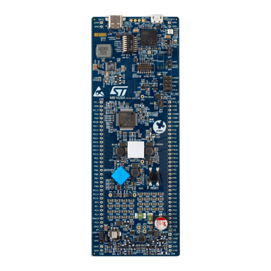
STMicroelectronics B-G474E-DPOW1 Manual (54 pages)
Discovery kit with STM32G474RE MCU
Brand:
STMicroelectronics
| Category:
Computer Hardware
| Size: 14 MB
Table of Contents
Figure 1. B-G474E-DPOW1 Top View
1
Figure 2. B-G474E-DPOW1 Bottom View
1
1 Features
2
2 Ordering Information
3
Product Marking
3
Table 1. Ordering Information
3
3 Development Environment
4
System Requirements
4
Development Toolchains
4
Demonstration Software
4
4 Technology Partners
5
5 Conventions
6
Table 2. ON/OFF Convention
6
6 Limitations
7
USB Type-C ® VBUS Limitation
7
Debug Connector Configuration
7
7 Quick Start
8
8 Hardware Layout and Configuration
9
Figure 3. Hardware Layout and Configuration
10
Product Layout (Top and Bottom)
11
Figure 4. B-G474E-DPOW1 Top Layout View
11
Figure 5. B-G474E-DPOW1 Bottom Layout View
12
Mechanical Drawing
13
Figure 6. B-G474E-DPOW1 Mechanical Drawing
13
9 Embedded STLINK-V3E
14
Figure 7. Configuration to Use STLINK-V3E
14
Deactivation
15
STLINK-V3E Physical Disconnection
15
Table 3. JP6 STLK NRST Configuration
15
Figure 8. JP6 STLK NRST Default Configuration
15
STLINK-V3E Drivers
16
Table 4. SW1 Configuration
16
Table 5. JP7 TNRST Configuration
16
Figure 9. SW1 and JP7 TNRST Default Configurations
16
STLINK-V3E VCP Configuration
17
Figure 10. USB Composite Device
17
10 Power Supply
18
Power Diagram
18
Figure 11. Power Diagram
19
Power Source Selection
20
Stlk
20
Table 6. JP5 5V_SEL Configuration
20
Figure 12. JP5 (STLK) from CN3 (USB STLK)
20
Chgr
21
Usbc
21
E5V
21
Figure 13. JP5 (CHGR) from CN3 (USB STLK)
21
Figure 14. JP5 (USBC) from CN2 (USB Type-C ® )
21
Microcontroller Power
22
Table 7. JP4 IDD Configuration
22
Figure 15. JP5 (E5V) from CN9 (5V_I / GND)
22
Figure 16. JP4 IDD Default Configuration
22
11 Clock Sources
23
12 Boot Options
24
13 Board Functions
25
USB Type-C
25
Power the 5V General Supply
25
Power Input to the Digital Power Buck-Boost Feature
26
Table 8. PD2 and PC12 Function
26
Table 9. Typical Current Protection on 5V_USBPD
26
Table 10. Typical Current Protection on CN2
26
Power and Data Input to the Audio Class-D Amplifier Feature
27
Digital Power Buck-Boost Converter
27
Figure 17. Digital Power Buck-Boost Converter
28
Figure 18. JP1 VIN Default Configuration
28
Audio Class-D Amplifier
29
RGB Power LED
29
Table 11. JP1 VIN Configuration
29
Extension Connector Headers
30
Figure 19. RGB Power LED Function
30
Figure 20. CN8 and CN9 Extension Connectors
31
RC Sinus Function
32
Joystick Function
32
Reset Button Function
32
Buttons and Leds Function
32
Table 12. Buttons and Leds
32
14 Connectors
33
CN2 USB Type-C Receptacle Connector
33
Table 13. USB Type-C ® CN2 Receptacle Connector
33
Figure 21. CN2 USB Type-C ® Receptacle Connector (Upper Front View)
33
CN1 Debug Connector
34
CN1 STDC14 Debug Connector
34
Table 14. STDC14 Connector
34
Figure 22. CN1 STDC14 Debug Connector
34
CN1 MIPI10 Debug Connector
35
Table 15. MIPI10 on STDC14 Footprint
35
Figure 23. CN1 MIPI10 Debug Connector
35
CN10 TAG Connector
36
CN9 Extension Connector
36
Table 16. CN10 TAG Connector
36
Table 17. CN9 Extension Connector
36
Figure 24. CN10 TAG Connector
36
CN8 Extension Connector
37
Table 18. CN8 Extension Connector
38
CN7 VOUT Extension Connector
39
CN5, CN6, CN11, and CN12 GND Extension Connectors
39
Table 19. CN7 Extension Connector
39
Table 20. CN5, CN6, CN11, and CN12 GND Extension Connectors
39
15 Jumpers and Solder Bridges
40
Jumpers
40
Table 21. Jumper Configuration
40
Solder Bridges
41
Table 22. Solder Bridges Configuration
41
16 STM32G474RET6 GPIO and Pin Assignment
44
Table 23. STM32G474RET6 GPIO and Pin Assignment
44
Appendix A Federal Communications Commission (FCC) and ISED Canada Compliance
46
Statements
46
FCC Compliance Statement
46
ISED Compliance Statement
46
Revision History
48
Table 24. Document Revision History
48
Table of Contents
49
Contents
49
List of Tables
52
List of Figures
53
Advertisement
Advertisement
Related Products
ST Microelectronics B-L475E-IOT01A
STMicroelectronics B-G431B-ESC1
STMicroelectronics B-L462E-CELL1
STMicroelectronics RM0365
STMicroelectronics ST62GP-EMU2 HDS2 Series
STMicroelectronics STEVAL-C34KAT1
STMicroelectronics STM32F302x6
STMicroelectronics STM32F302x8
STMicroelectronics STM32F302xB
STMicroelectronics STM32F302xC
STMicroelectronics Categories
Motherboard
Microcontrollers
Computer Hardware
Controller
Control Unit
More STMicroelectronics Manuals
Login
Sign In
OR
Sign in with Facebook
Sign in with Google
Upload manual
Upload from disk
Upload from URL