Sign In
Upload
Manuals
Brands
Silicon Graphics Manuals
Server
POWER CHALLENGE
Silicon Graphics POWER CHALLENGE Manuals
Manuals and User Guides for Silicon Graphics POWER CHALLENGE. We have
1
Silicon Graphics POWER CHALLENGE manual available for free PDF download: User Manual
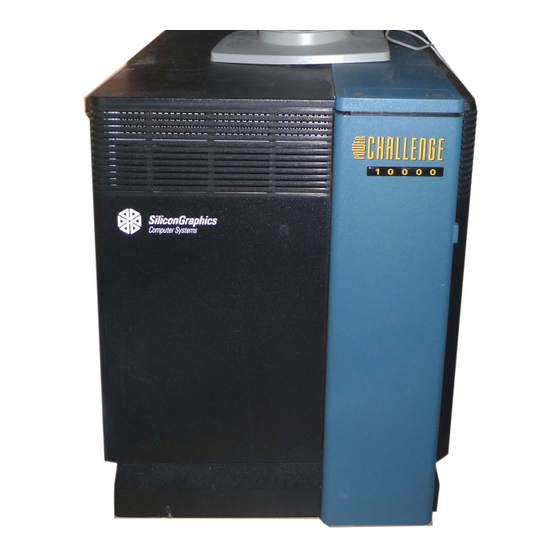
Silicon Graphics POWER CHALLENGE User Manual (164 pages)
deskside server
Brand:
Silicon Graphics
| Category:
Server
| Size: 1 MB
Table of Contents
Table of Contents
3
List of Figures
9
About this Guide
13
Conventions
14
Compliance Information
15
Figure In-1 VCCI Information
16
Figure In-2 CE Insignia
16
1 Introducing the Challenge Deskside Servers
17
Features and Options
17
The Challenge Board Set
18
Figure 1-1 Challenge Deskside System Functional Block Diagram
20
I/O Interfaces
21
Ibus Interface
21
Flat Cable Interface
22
Vmebus Interface
22
SCSI-2 Interface
23
Ethernet Interface
23
Parallel Port
23
Serial Ports
23
System and SCSI Backplanes
24
SCSI I/O Devices
24
System Controller
24
Operating Considerations
25
Table 1-1 Required Air Clearances for the Deskside Chassis
25
2 Touring the Chassis
27
Figure 2-1 Chassis Front and Rear Views
28
Challenge Deskside System I/O Panels and Connectors
29
The I/O Panel
29
Figure 2-2 Basic I/O Panel Configuration
30
Table 2-1 Standard I/O Connectors
31
Figure 2-3 Optional Visualization Console I/O Panel Graphics Connectors
32
Serial and DIN Connectors
33
Table 2-2 Optional Visualization Console Video Connector
33
Enabling Additional Serial Ports
34
Figure 2-4 RS-232 and RS-422 Serial Connectors
34
Table 2-3 Server System IO4 Board Connector Labelling
35
Figure 2-5 RS-232 Powered 8-Pin DIN Connector
36
Parallel Printer Ports
37
Table 2-4 Centronics Compatible Parallel Port Pin Assignments
37
System Controller
38
Figure 2-6 Challenge Deskside System Controller and Drives Location
39
Cooling System
40
SCSI Drive Rack
40
Figure 2-7 Chassis Cooling
42
Power Supplies
43
Figure 2-8 Power Receptacle and Circuit Breaker on Rear Panel
44
3 Getting Started
45
Chassis Components
45
Figure 3-1 Challenge Deskside Components
46
Opening the Front Door
47
Figure 3-2 Opening the Chassis Front Door
48
Internal Front-Loading Drives
49
SCSI Limitations
49
Figure 3-3 Connecting an Ethernet Cable
52
Powering on the Challenge Deskside System
53
Table 3-1 System Controller Boot Status Messages
54
Powering off the Challenge Deskside System
55
Rebooting Your System
55
Figure 3-4 Key Switch Positions on the System Controller Front Panel
56
4 Installing Optional Peripherals
57
SCSI Configuration
57
Installing and Configuring Additional Flds
59
Table 4-1 Overview of Drive Installation Guidelines
59
Installing a Half-Height FLD
63
Figure 4-3 Installing a Half-Height SCSI Drive on a Sled and Loading
64
Removing an FLD
65
Figure 4-4 Drive Removal Example
66
Installing a Full-Height FLD
67
Figure 4-5 Pulling off the Side Panel and Removing the Retaining
68
Figure 4-6 Installing a Full-Height Front Loading Device
69
Installing and Using an Optional CD-ROM
71
Figure 4-8 Loading a Disc into the CD-ROM Caddy
72
Figure 4-9 Disc Loaded in Caddy
73
Installing External SCSI Devices
74
Figure 4-10 CD-ROM Drive Front Panel Controls
74
Figure 4-11 Connecting an External SCSI Device
75
Figure 4-12 Single-Ended 68-Pin Connector
76
Table 4-2 68-Pin Single-Ended, High-Density SCSI Pinouts
76
Figure 4-13 68-Pin Differential SCSI Connector
78
Table 4-3 68-Pin Differential, High-Density SCSI Pinouts
78
Connecting a Serial Printer
80
Table 4-4 Typical DTE to DTE Serial Printer Connection
80
Figure 4-14 Connecting a Serial Printer or Modem
82
Connecting an ASCII Terminal
84
Table 4-5 Typical ASCII Terminal Connection
84
Helpful Serial Port Commands
86
Connecting a Modem
87
Table 4-6 RS-232 Modem Connector Pin Assignments
87
Connecting a Parallel Printer
88
Table 4-7 Centronics Compatible Parallel Port Pin Assignments
90
Figure 4-15 Connecting a Parallel Printer Cable
91
5 Having Trouble
93
Maintaining Your Hardware and Software
93
Hardware Do's and Don'ts
93
Software Do's and Don'ts
94
System Behavior
94
Physical Inspection Checklist
95
Using the System Controller
96
The Power-On Process
97
If the System Hangs
98
System Controller on Functions
98
Figure 5-1 System Controller Front Panel Components
100
The Event History Log Menu
101
The Master CPU Selection Menu
101
Boot Status Menu
102
Table 5-1 System Controller Master CPU Status Messages
102
The CPU Activity Display
103
Recovering from a System Crash
104
Figure 5-2 Challenge CPU Board Microprocessor Activity Graph
104
6 Safety and Comfort
107
Human Factors Guidelines for Setting up Your Workstation
107
ANSI Standard for VDT Workstations
108
Figure 6-1 Basic Parameters of VDT Workstation Adjustment (Adapted from ANSI/HFS 100-1988)
108
CAD Operator Preferences
109
Table 6-1 ANSI/HFS 100-1988 Guidelines for VDT Workplace
109
Table 6-2 Workstation Adjustments Preferred by CAD Users
109
Tips for Setting up and Using Your Workstation
110
Facilities Selection
110
Adjusting Your Chair, Work Surface, and Monitor
111
System Usage
111
Electrostatic Discharge
112
Hardware Specifications
113
Table A-1 Challenge Deskside Server Specifications
113
Maintaining Drives
115
Cleaning the 4 MM DAT and 8 MM Tape Drives
115
Archive Python 4320 NT (4 MM DAT Drive)
116
Loading and Unloading Cassettes
116
Removing a Jammed 4 MM Cassette
116
Cleaning the 4 MM DAT Drive
117
Front Panel Lights
117
Table B-1 4 MM DAT Front Panel LED Status Indicators
117
Care and Cleaning of the Exabyte 8 MM Tape Drive
118
Front Panel Lights
118
Removing a Jammed 8 MM Tape Cartridge
119
Table B-2 8 MM Tape Drive Front Panel Status Indicators
119
CD-ROM Care and Maintenance
120
CD-ROM Environmental Considerations
121
Figure B-1 Handling a Compact Disc
121
CD-ROM Front Panel Operational Features
122
150 MB Tape Drive Preventive Maintenance
123
Figure B-2 CD-ROM Drive LED Status Indicators
123
Digital Linear Tape Maintenance
125
Figure B-3 Cleaning the Tape Head
125
Figure B-4 DLT Cleaning Cartridge
126
Loading a Cleaning Cartridge
126
DLT Tape Cartridge Care and Handling
127
Removing a Jammed Tape Cartridge
128
System Controller Messages
129
Table C-1 System Events - Immediate Power-Off
129
Table C-2 System Events - Delayed Power-Off
131
Table C-3 System Events - Informative
132
Table C-4 Internal System Controller Error Messages
133
Challenge IO4 PROM, Mezzanine, and Troubleshooting
137
Hardware Configuration Commands
137
Checking and Updating the Hardware Inventory
137
Displaying Information about the Current Hardware Configuration
138
POD (Power on Diagnostics) Mode
139
Environment Variables
139
Booting from an Alternate Device
139
Starting the System Automatically
140
Allowing the System to Boot in Spite of Nonterminal Hardware Failures
141
Restoring Defaults
141
Known Bugs
141
A Spurious CD-ROM Medium Is Displayed During Startup
141
Disk Formatting Fails Using Standalone Fx
142
Mezzanine Board Configurations
142
Mezzanine Options Available with One IO4
143
Table D-1 Optional Mezzanine Board Descriptions
143
Mezzanine Options Available with Two Io4S
144
Figure D-1 IO4 with VCAM and GCAM
144
Mezzanine Options Available with Three Io4S
145
Figure D-2 Mezzanine Types Available with Optional Second IO4
145
Figure D-3 Optional Second and Third IO4 Configuration
146
IO4 Troubleshooting
147
Challenge Vmebus Implementation
149
General Information
149
VME Board Dimensions
150
Deskside VME Power and Cooling
150
Exceeding the Normal VME Power Rating Per Slot
150
Special VME Considerations
151
Table E-1 P1 VME Pin Assignments
152
Table E-2 P2 VME Pin Assignments
154
Advertisement
Advertisement
Related Products
Silicon Graphics CHALLENGE L
Silicon Graphics Rackable C1000
Silicon Graphics Rackable C2005 2U
Silicon Graphics Rackable C1110-RP6
Silicon Graphics Rackable C2005 Family
Silicon Graphics Rackable C2112-4G3
Silicon Graphics Rackable C2110G-RP5
Silicon Graphics Rackable C1110-GP2
Silicon Graphics Rackable C1104-GP2
Silicon Graphics Rackable C2112-4GP3
Silicon Graphics Categories
Server
Desktop
Storage
Monitor
Computer Hardware
More Silicon Graphics Manuals
Login
Sign In
OR
Sign in with Facebook
Sign in with Google
Upload manual
Upload from disk
Upload from URL