Sign In
Upload
Manuals
Brands
Siemens Manuals
Media Converter
6SL3210-5BE24-0UV0
Siemens 6SL3210-5BE24-0UV0 Manuals
Manuals and User Guides for Siemens 6SL3210-5BE24-0UV0. We have
1
Siemens 6SL3210-5BE24-0UV0 manual available for free PDF download: Operating Instructions Manual
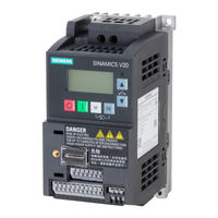
Siemens 6SL3210-5BE24-0UV0 Operating Instructions Manual (426 pages)
Low voltage converters
Brand:
Siemens
| Category:
Media Converter
| Size: 30.17 MB
Table of Contents
Legal Information
4
Preface
5
Table of Contents
9
1 Fundamental Safety Instructions
13
General Safety Instructions
13
Equipment Damage Due to Electric Fields or Electrostatic Discharge
18
Warranty and Liability for Application Examples
18
Industrial Security
19
Residual Risks of Power Drive Systems
20
2 Introduction
21
Converter Variants
21
Converter Rating Plate
23
3 Mechanical Installation
25
Mounting Orientation and Clearance
25
Mounting in a Control Cabinet
26
Mounting a SINAMICS V20 Flat Plate Variant
29
Push-Through Mounting (Frame Sizes B
31
DIN Rail Mounting (Frame Sizes AA, AB, AC, A, and B)
34
4 Electrical Installation
37
Typical System Connections
38
Terminal Description
42
Using Several Single-Phase Converters in Machines and Plants
49
EMC-Compliant Installation
50
EMC-Compliant Cabinet Design
53
5 Commissioning Via the Built-In BOP
55
The Built-In Basic Operator Panel (BOP)
55
Introduction to the Built-In BOP
55
Converter Menu Structure
57
Viewing Converter Status
59
Editing Parameters
59
Screen Displays
62
LED States
63
Checking before Power-On
64
Setting the 50/60 Hz Selection Menu
64
Starting the Motor for Test Run
65
Quick Commissioning
65
Quick Commissioning through the Setup Menu
65
Structure of the Setup Menu
65
Setting Motor Data
66
Setting Connection Macros
68
Setting Application Macros
79
Setting Common Parameters
81
Quick Commissioning through the Parameter Menu
82
Function Commissioning
86
Overview of Converter Functions
86
Commissioning Basic Functions
88
Selecting the Stop Mode
88
Running the Converter in JOG Mode
90
Setting the Voltage Boost
92
Setting the PID Controller
94
Setting the Braking Function
96
Setting the Ramp Time
105
Setting the Imax Controller
107
Setting the VDC Controller
108
Setting the Load Torque Monitoring Function
110
Commissioning Advanced Functions
111
Starting the Motor in Super Torque Mode
111
Starting the Motor in Hammer Start Mode
113
Starting the Motor in Blockage Clearing Mode
115
Running the Converter in Economy Mode
117
Setting the UL508C/UL61800-5-1-Compliant Motor Overtemperature Protection
118
Motor Protection with PTC Sensor
118
Setting the Free Function Blocks (Ffbs)
120
Setting the Flying Start Function
121
Setting the Automatic Restart Function
122
Running the Converter in Frost Protection Mode
123
Running the Converter in Condensation Protection Mode
124
Running the Converter in Hibernation Mode
125
Setting the Wobble Generator
128
Running the Converter in Motor Staging Mode
129
Running the Converter in Cavitation Protection Mode
132
Setting the User Default Parameter Set
133
Setting the Dual Ramp Function
134
Setting the DC Coupling Function
135
Setting High/Low Overload (HO/LO) Mode
138
Restoring to Defaults
140
6 Commissioning Via the SINAMICS V20 Smart Access
141
System Requirements
142
Accessing the SINAMICS V20 Web Pages
142
Overview of the Steps
143
Fitting SINAMICS V20 Smart Access to the Converter
143
Establishing the Wireless Network Connection
144
Accessing the Web
146
Overview of the Web
147
Viewing Connection Status
148
Viewing Converter Information
148
Making Optional Web Access Settings
149
Configuring Wi-Fi
149
Changing the Display Language
151
Synchronizing the Time
151
Upgrading
151
Viewing Additional Information
152
Quick Commissioning
152
Setting Parameters
157
Starting Motor Test Run (JOG/HAND)
162
Monitoring
165
Diagnosing
165
Backing up and Restoring
168
Backing up
168
Restoring
170
Upgrading
172
Viewing the Support Information
175
7 Communicating with the PLC
177
USS Communication
177
MODBUS Communication
181
8 Parameter List
195
Introduction to Parameters
195
Parameter List
200
9 Faults and Alarms
335
Faults
335
Alarms
343
Technical Specifications
347
Mechanical Specifications
352
Environmental Conditions
353
Options and Spare Parts
359
Options
359
Parameter Loader
359
External BOP and BOP Interface Module
364
Dynamic Braking Module
369
Braking Resistor
372
Line Reactor
377
Output Reactor
383
External Line Filter
387
Shield Connection Kits
393
Memory Card
398
RS485 Termination Resistor
398
Residual Current Circuit Breaker (RCCB)
398
DIN Rail Mounting Kits (Only for FSAA, AB, AC, A, and B)
399
Migration Mounting Kit for FSAA
400
SINAMICS V20 Smart Access
402
I/O Extension Module
404
User Documentation
406
Spare Parts - Replacement Fans
406
General License Conditions
413
Index
419
Advertisement
Advertisement
Related Products
Siemens 6SL3210-1KE11-8UB2
Siemens 6SL3210-1KE11-8AP2
Siemens 6SL3210-1KE11-8AF2
Siemens 6SL3210-1KE12-3UF2
Siemens 6SL3210-1KE18-8AP1
Siemens 6SL3210-1KE21-3UB1
Siemens 6SL3210-1KE21-3AB1
Siemens 6SL3210-1KE21-3AP1
Siemens 6SL3210-1KE21-7UP1
Siemens 6SL3210-1KE23-2AF1
Siemens Categories
Industrial Equipment
Controller
Control Unit
Oven
Washer
More Siemens Manuals
Login
Sign In
OR
Sign in with Facebook
Sign in with Google
Upload manual
Upload from disk
Upload from URL