Sign In
Upload
Manuals
Brands
Sensopart Manuals
Accessories
FT 50 RLA 220-L8
Sensopart FT 50 RLA 220-L8 Manuals
Manuals and User Guides for Sensopart FT 50 RLA 220-L8. We have
3
Sensopart FT 50 RLA 220-L8 manuals available for free PDF download: Mounting And Operating Instructions
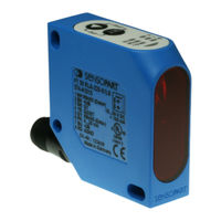
Sensopart FT 50 RLA 220-L8 Mounting And Operating Instructions (122 pages)
Distance sensor
Brand:
Sensopart
| Category:
Accessories
| Size: 9.41 MB
Table of Contents
Deutsch
5
Table of Contents
5
Inhaltsverzeichnis
5
1 Symbolerklärung
6
2 Sicherheitshinweise
6
3 Bestimmungsgemäße Verwendung
7
4 Leistungsmerkmale
7
5 Montage
8
Maßzeichnung
8
Sensormontage
8
6 Elektrische Installation
9
7 Bedienung und Einstellung
10
Anzeigen und Einstellelemente
11
Funktionen über das Bedienfeld Einstellen
13
Kurzanleitung (068-13884) Siehe Ausklappseite
13
Mögliche Einstellungen und Betriebsarten
13
Modus Differenzmessung
20
8 Kommunikation über die Serielle Schnittstelle
23
Grundlegende Eigenschaften und Parameter der Seriellen Sensor-Schnittstelle
23
Beschreibung des Protokolls
23
Telegrammaufbau
24
Übersicht der Masterbefehle
25
Beispiele für Masterbefehle
27
Schaltausgang Q1 Setzen
27
Schaltausgang Q2 Setzen
28
Q2 als Ausgang „Good Target" Setzen
28
Q1 als Triggereingang Setzen
29
Q1 als Steuereingang für Laser ein / aus Setzen
29
Mittelwertbildung
30
Analogausgang Skalieren (4 Ma-Punkt Setzen)
30
Analogausgang Skalieren (20 Ma-Punkt Setzen)
31
Funktion „Autozero" (mit Q1 als Steuereingang)
31
Funktion „Autocenter" (mit Q1 als Steuereingang)
32
Funktion „Maximum-Hold" (mit Q1 als Steuereingang)
32
Funktion „Minimum-Hold" (mit Q1 als Steuereingang)
33
Funktion „Differenz-Hold" (mit Q1 als Steuereingang)
33
Werkseinstellung Aktivieren
34
Tastenfeld Verriegeln und Entriegeln
34
Einstellungen Dauerhaft Speichern
35
Q1-Eingang Setzen
35
Abstandsmesswerte
36
Betriebsmesswerte
36
Schnelle Messwertausgabe
37
Adresse des Sensors Ändern
37
Sensoreinstellung Lesen
38
Funktion „Messwert-Hold
39
9 Pflege und Wartung
40
Reinigung
40
Transport, Verpackung, Lagerung
40
Entsorgung
40
10 Fehlersuche (Troubleshooting)
40
11 Technische Daten
41
12 Bestellinformationen
42
Zubehör
42
English
43
Contents
43
1 Guide to Symbols
44
2 Safety Instructions
44
3 Correct Use
45
4 Performance
45
5 Mounting
46
Dimensional Drawing
46
Mounting the Sensor
46
6 Electrical Installation
47
7 Use and Configuration
48
Displays and Configuration Elements
49
Setting Functions with the Control Panel
50
Quick User Guide (068-13884) See Fold-Out Page
50
Possible Configurations and Operating Modes
51
Differential Measurement Mode
58
8 Communication Via the Serial Interface
61
Basic Characteristics and Parameters of the Serial Sensor Interface
62
Description of Protocol
62
Telegram Structure
62
Overview of Master Commands
64
Examples for Master Commands
65
Set Switching Output Q1
66
Set Switching Output Q2
66
Set Q2 as Output „Good Target
67
Set Q1 as Trigger Input
67
Set Q1 as Control Input for Laser on / off
68
Averaging
68
Scaling Analogue Output (Set 4 Ma Point)
69
Scaling Analogue Output (Set 20 Ma Point)
69
Autom. Zero" Function (with Q1 as Control Input)
70
Autom. Centre" (with Q1 as Control Input)
70
Maximum-Hold" Function (with Q1 as Control Input)
71
Minimum-Hold" Function (with Q1 as Control Input)
71
Difference Hold" Function (with Q1 as Control Input)
72
Activate Factory Setting
72
Lock and Unlock Keys
72
Permanent Storage of Configurations
73
Set Q1 Input
73
Distance Measured Values
74
Operating Measured Values
74
Fast Measured Value Output
75
Change the Sensor's Address
75
Read Sensor Settings
76
Meas. Value Hold" Function
77
9 Care and Maintenance
78
Cleaning
78
Transport, Packaging, Storage
78
Disposal
78
10 Troubleshooting
78
11 Technical Data
79
12 Order Information
80
Accessories
80
Français
82
1 Explication des Symboles
83
2 Instructions de Sécurité
83
3 Utilisation Conforme À la Destination de L'appareil
84
4 Caractéristiques de Fonctionnement
84
5 Montage
85
Plan Coté
85
Montage du Capteur
85
6 Installation Électrique
86
7 Commande Et Réglage
87
Témoins de Fonctionnement Et Éléments de Réglage
88
Régler Fonctions de L'interface des Commandes
89
Guide Compact (068-13884) Voir
89
Réglages Et Modes de Fonctionnement Possibles
90
Mode Mesure D'une Différence
98
8 Communication Via L'interface Série
101
Propriétés Et Paramètres de Base de L'interface Série du Capteur
102
Description du Protocole
102
Structure de Télégramme
102
Aperçu des Commandes Maître
104
Exemples de Commandes Maître
106
Régler Sortie de Commutation Q1
106
Régler Sortie de Commutation Q2
106
Régler Q2 Sortie de Commutation en „ Good Target
107
Régler Q1 Comme Entrée Trigger
108
Régler Q1 en Entrée de Commande Pour Laser on / off
108
Recherche de la Moyenne
108
Graduer la Sortie Analogique (Régler Point 4 Ma)
109
Graduer la Sortie Analogique (Régler Point 20 Ma)
109
Fonction „ Autozero " (Avec Q1 en Entrée de Commande)
110
Fonction „Autocenter" (Avec Q1 en Entrée de Commande)
110
Fonction „ Hold Maxi " (Avec Q1 en Entrée de Commande)
111
Fonction „ Hold Mini " (Avec Q1 en Entrée de Commande)
111
Fonction „ Hold Différence " (Avec Q1 en Entrée de Commande)
112
Activer la Configuration Usine
112
Verrouiller Et Déverrouiller Le Clavier
112
Sauvegarde Définitive des Réglages
113
Régler L'entrée Q1
113
Valeurs de Mesure de Distance
114
Valeurs Mesurées de Fontionnement
114
Transmission Rapide des Valeurs Mesurées
115
Modifier L'adresse du Capteur
115
Lecture des Réglages Capteur
116
Fonction „ Hold Valeur Mesurée
117
9 Entretien Et Maintenance
118
Nettoyage
118
Transport, Emballage, Stockage
118
Elimination
118
10 Recherche des Défauts (Troubleshooting)
118
11 Caractéristiques Techniques
119
12 Référence de Commande
120
Accessoires
120
Advertisement
Sensopart FT 50 RLA 220-L8 Mounting And Operating Instructions (126 pages)
Distance sensor
Brand:
Sensopart
| Category:
Accessories
| Size: 12.62 MB
Table of Contents
Deutsch
5
Table of Contents
5
Inhaltsverzeichnis
5
Symbolerklärung
6
Sicherheitshinweise
6
Bestimmungsgemäße Verwendung
7
Leistungsmerkmale
7
Sensormontage
8
Maßzeichnung
8
Montage
8
Elektrische Installation
9
Bedienung und Einstellung
10
Anzeigen und Einstellelemente
10
Funktionen über das Bedienfeld Einstellen
12
Kurzanleitung (068-13884) Siehe Ausklappseite
12
Mögliche Einstellungen und Betriebsarten
12
Modus Differenzmessung
19
Kommunikation über die Serielle Schnittstelle
22
Beschreibung des Protokolls
23
Grundlegende Eigenschaften und Parameter der Seriellen Sensor-Schnittstelle
23
Telegrammaufbau
24
Übersicht der Masterbefehle
25
Beispiele für Masterbefehle
27
Schaltausgang Q1 Setzen
27
Schaltausgang Q2 Setzen
28
Q2 als Ausgang „Good Target" Setzen
28
Q1 als Triggereingang Setzen
29
Q1 als Steuereingang für Laser ein / aus Setzen
29
Mittelwertbildung
30
Analogausgang Skalieren (4 Ma-Punkt Setzen)
30
Analogausgang Skalieren (20 Ma-Punkt Setzen)
31
Funktion „Autozero" (mit Q1 als Steuereingang)
31
Funktion „Autocenter" (mit Q1 als Steuereingang)
32
Funktion „Maximum-Hold" (mit Q1 als Steuereingang)
32
Funktion „Minimum-Hold" (mit Q1 als Steuereingang)
33
Funktion „Differenz-Hold" (mit Q1 als Steuereingang)
33
Werkseinstellung Aktivieren
34
Tastenfeld Verriegeln und Entriegeln
34
Q1-Eingang Setzen
35
Einstellungen Dauerhaft Speichern
35
Abstandsmesswerte
36
Betriebsmesswerte
36
Schnelle Messwertausgabe
37
Adresse des Sensors Ändern
37
Sensoreinstellung Lesen
38
Funktion „Messwert-Hold
39
Fehlersuche (Troubleshooting)
40
Entsorgung
40
Transport, Verpackung, Lagerung
40
Reinigung
40
Pflege und Wartung
40
Technische Daten
41
Bestellinformationen
42
Zubehör
42
English
43
Contents
43
Guide to Symbols
44
Safety Instructions
44
Correct Use
45
Performance
45
Mounting
46
Mounting the Sensor
46
Electrical Installation
47
Displays and Configuration Elements
48
Use and Configuration
48
Possible Configurations and Operating Modes
50
Quick User Guide (068-13884) See Fold-Out Page
50
Setting Functions with the Control Panel
50
Differential Measurement Mode
58
Communication Via the Serial Interface
61
Basic Characteristics and Parameters of the Serial Sensor Interface
62
Description of Protocol
62
Telegram Structure
62
Overview of Master Commands
64
Examples for Master Commands
66
Set Switching Output Q1
66
Set Switching Output Q2
66
Set Q2 as Output „Good Target
67
Set Q1 as Control Input for Laser on / off
68
Set Q1 as Trigger Input
68
Averaging
69
Scaling Analogue Output (Set 4 Ma Point)
69
Autom. Zero" Function (with Q1 as Control Input)
70
Scaling Analogue Output (Set 20 Ma Point)
70
Autom. Centre" (with Q1 as Control Input)
71
Maximum-Hold" Function (with Q1 as Control Input)
71
Activate Factory Setting
72
Difference Hold" Function (with Q1 as Control Input)
72
Minimum-Hold" Function (with Q1 as Control Input)
72
Lock and Unlock Keys
73
Permanent Storage of Configurations
73
Measured Distance Values
74
Set Q1 Input
74
Fast Measured Value Output
75
Measured Operating Values
75
Change the Sensor's Address
76
Read Sensor Settings
76
Care and Maintenance
78
Cleaning
78
Disposal
78
Meas. Value Hold" Function
78
Transport, Packaging, Storage
78
Troubleshooting
79
Technical Data
80
Accessories
81
Order Information
81
Français
82
Explication des Symboles
83
Instructions de Sécurité
83
Caractéristiques de Fonctionnement
84
Utilisation Conforme à la Destination de L'appareil
84
Montage
85
Montage du Capteur
85
Plan Coté
85
Installation Électrique
86
Commande et Réglage
87
Témoins de Fonctionnement et Éléments de Réglage
87
Guide Compact (068-13884) Voir Page Supp
89
Régler les Fonctions de L'interface des Commandes
89
Réglages et Modes de Fonctionnement Possibles
90
Mode Mesure D'une Différence
97
Communication Via L'interface Série
101
Description du Protocole
101
Propriétés et Paramètres de Base de L'interface Série du Capteur
101
Structure de Télégramme
102
Aperçu des Commandes Maître
103
Exemples de Commandes Maître
105
Régler Sortie de Commutation Q1
105
Régler Q1 comme Entrée Trigger
107
Régler Q2 Sortie de Commutation en „ Good Target
107
Recherche de la Moyenne
108
Graduer la Sortie Analogique (Régler Point 20 Ma)
109
Graduer la Sortie Analogique (Régler Point 4 Ma)
109
Fonction „ Autozero " (Avec Q1 en Entrée de Commande)
110
Fonction „Autocenter" (Avec Q1 en Entrée de Commande)
110
Fonction „ Hold Maxi " (Avec Q1 en Entrée de Commande)
111
Fonction „ Hold Mini " (Avec Q1 en Entrée de Commande)
111
Activer la Configuration Usine
112
Fonction „ Hold Différence " (Avec Q1 en Entrée de Commande)
112
Verrouiller et Déverrouiller le Clavier
112
Régler L'entrée Q1
113
Sauvegarde Définitive des Réglages
113
Valeurs de Mesure de Distance
114
Valeurs Mesurées de Fontionnement
114
Modifier L'adresse du Capteur
115
Transmission Rapide des Valeurs Mesurées
115
Lecture des Réglages Capteur
116
Fonction „ Hold Valeur Mesurée
117
Elimination
118
Entretien et Maintenance
118
Recherche des Défauts (Troubleshooting)
118
Transport, Emballage, Stockage
118
Caractéristiques Techniques
119
12 Référence de Commande
120
Accessoires
121
Sensopart FT 50 RLA 220-L8 Mounting And Operating Instructions (88 pages)
Distance sensor
Brand:
Sensopart
| Category:
Accessories
| Size: 4.62 MB
Table of Contents
汉语
5
Table of Contents
5
1 标识说明
6
2 安全须知
6
3 应用说明
7
尺寸图
8
传感器安装
8
6 电气安装
9
7 操作和设置
10
显示和设置
10
通过控制面板进行功能设置
12
简要说明(068-13884)请参阅折叠页
12
设置和运行模式
12
差值测量模式
19
8 通过串行接口通讯
22
传感器串行接口的基本特征及参数
22
协议说明
23
报文结构
23
主站命令一览
25
主站命令示例
26
设置Q 开关量输出
27
设置为"Good Target"输出
28
设置为触发输入
29
求平均值
30
按比例模拟量输出(设置4Ma点
30
按比例模拟量输出(设置20Ma点
31
自动回零"功能(Q
31
为控制输入
32
自动居中"功能(Q 为控制输入
32
最大值保持"功能(Q
32
最小值保持"功能(Q
33
为控制输入
33
差异保持"功能(Q
33
恢复出厂设置
34
按键的锁定和解锁
34
永久保存设置
35
设置Q
35
距离测量值
35
运行测量值
36
测量值的快速输出
36
更改传感器地址
37
读取传感器的设置
37
测量值保持功能
39
9 保养与维护
40
运输 包装 仓储
40
10 故障排除
40
11 技术参数
41
12 订购信息
42
English
43
Contents
43
1 Guide to Symbols
44
2 Safety Instructions
44
3 Correct Use
45
4 Performance
45
5 Mounting
46
Dimensional Drawing
46
Mounting the Sensor
47
6 Electrical Installation
48
Use And Configuration
49
Displays And Configuration Elements
49
Setting Functions with the Control Panel
51
Quick User Guide (068-13884) See Fold-Out Page
51
Possible Configurations And Operating Modes
51
Differential Measurement Mode
60
8 Communication Via the Serial Interface
64
Basic Characteristics and Parameters of the Serial Sensor Interface
64
Description of Protocol
65
Telegram Structure
65
Overview of Master Commands
67
Examples for Master Commands
69
Set Switching Output Q1
69
Set Switching Output Q2
70
Set Q2 as Output „Good Target
71
Set Q1 as Trigger Input
71
Set Q1 as Control Input for Laser on / off
72
Averaging
72
Scaling Analogue Output (Set 4 Ma Point)
73
Scaling Analogue Output (Set 20 Ma Point)
73
Autom. Zero" Function (with Q1 as Control Input)
74
Autom. Centre" (with Q1 as Control Input)
74
Maximum-Hold" Function (with Q1 as Control Input)
75
Minimum-Hold" Function (with Q1 as Control Input)
75
Difference Hold" Function (with Q1 as Control Input)
76
Activate Factory Setting
76
Lock and Unlock Keys
77
Permanent Storage Of Configurations
77
Set Q1 Input
78
Measured Distance Values
78
Measured Operating Values
79
Fast Measured Value Output
80
Change the Sensor's Address
80
Read Sensor Settings
81
Meas. Value Hold" Function
83
9 Care and Maintenance
83
Cleaning
83
Transport, Packaging, Storage
83
Disposal
84
10 Troubleshooting
84
11 Technical Data
84
12 Order Information
86
Accessories
86
Advertisement
Advertisement
Related Products
Sensopart FT 50 RLA 220-S1L8
Sensopart FT 50 RLA 70-L8
Sensopart FT 50 RLA 70-S1L8
Sensopart FT 50 RLA 100-L8
Sensopart FT 50 RLA 100-S1L8
Sensopart FT 80 RLA 500-L8
Sensopart FT 80 RLA 500-S1L8
Sensopart FT 50 RLA Series
Sensopart FT 50 C S1 Series
Sensopart FT 50 C GIO Series
Sensopart Categories
Accessories
Analytical Instruments
Switch
Monitor
Security Sensors
More Sensopart Manuals
Login
Sign In
OR
Sign in with Facebook
Sign in with Google
Upload manual
Upload from disk
Upload from URL