Sign In
Upload
Manuals
Brands
Satec Manuals
Measuring Instruments
PM172E
Satec PM172E Manuals
Manuals and User Guides for Satec PM172E. We have
3
Satec PM172E manuals available for free PDF download: Installation And Operation Manual, Reference Manual, Quick Start Manual
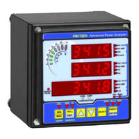
Satec PM172E Reference Manual (88 pages)
Series PM172 Powermeters
Brand:
Satec
| Category:
Measuring Instruments
| Size: 0 MB
Table of Contents
Table of Contents
3
General
8
Modbus Protocol Implementation
9
Transmission Modes
9
Address Field
9
Function Field
9
Exception Responses
9
Modbus Register Addresses
9
Data Formats
10
16-Bit Scaled Integer Format
10
32-Bit Long Integer Format
11
32-Bit Modulo-10000 Format
12
User Assignable Registers
12
Password Protection
12
Data Recording and File Transfers
13
Log File Organization
13
Multi-Section Files
13
Data Log Files
13
Profile Data Log File
14
Waveform Log Files
14
File Transfers
14
Common File Transfer
14
Reading a Profile Log File
15
Reading Waveform Files
15
Reading Real-Time Waveforms
16
TCP Notification Client
16
Modbus Register Map
18
Modbus Setup Registers
18
Modbus Assignable Registers
18
Assignable Registers Map
18
Modbus Conversion Scales
18
Device Data Scales
18
16-Bit Scaled Analog Registers and Energy Counters - Basic Register Set
19
16-Bit Scaled Analog Registers, Binary Registers and Counters
21
None
21
Special Inputs
21
Event Flags (Bitmap) Digital Inputs (Bitmap)
21
Relay Outputs (Bitmap)
21
Counters
21
1-Cycle Phase Values
21
1-Cycle Total Values
22
1-Cycle Auxiliary Values
22
Phasor
22
1-Second Phase Values
23
1-Second Total Values
23
1-Second Auxiliary Values
24
Present Harmonic Demands
24
Present Volt, Ampere and Power Demands
24
Total Energies
25
Phase Energies
25
V1/V12 Harmonic Distortions
25
V3/V31 Harmonic Distortions
26
I1 Harmonic Distortions
26
I2 Harmonic Distortions
26
I3 Harmonic Distortions
26
Fundamental (H01) Phase Values
26
Harmonic Total Values
27
Minimum 1-Cycle Phase Values
27
Minimum 1-Cycle Total Values
27
Minimum 1-Cycle Auxiliary Values
27
Maximum 1-Cycle Phase Values
28
Maximum 1-Cycle Total Values
28
Maximum 1-Cycle Auxiliary Values
28
Maximum Demands
28
Maximum Harmonic Demands
29
Scaled Analog Inputs
29
Raw Analog Inputs
29
TOU Parameters
29
Scaled Analog Outputs
29
TOU Energy Register #1
29
TOU Energy Register #2
29
TOU Energy Register #3
30
TOU Energy Register #4
30
TOU Energy Register #5
30
TOU Energy Register #6
30
TOU Energy Register #7
30
TOU Energy Register #8
30
Summary Energy Accumulated Demands
30
Summary Energy Block Demands
30
Summary Energy Sliding Window Demands
31
Summary Energy Maximum Demands
31
TOU Maximum Demand Register #1
31
TOU Maximum Demand Register #2
31
TOU Maximum Demand Register #3
31
TOU Maximum Demand Register #4
31
TOU Maximum Demand Register #5
31
TOU Maximum Demand Register #6
31
TOU Maximum Demand Register #7
32
TOU Maximum Demand Register #8
32
V1/V12 Harmonic Angles
32
V2/V23 Harmonic Angles
32
V1/V31 Harmonic Angles
32
I1 Harmonic Angles
32
I2 Harmonic Angles
32
I3 Harmonic Angles
32
Setpoint Status (Bitmap)
33
32-Bit Analog Registers, Binary Registers and Counters
34
Special Inputs
34
Event Flags (Bitmap)
34
Digital Inputs DI1-DI2 (Bitmap)
34
Relay Outputs RO1-RO2 (Bitmap)
34
Counters
34
1-Cycle Phase Values
34
1-Cycle Total Values
35
1-Cycle Auxiliary Values
35
Phasor
35
1-Second Phase Values
36
1-Second Total Values
36
1-Second Auxiliary Values
37
Present Harmonic Demands
37
Present Volt, Ampere and Power Demands
37
Total Energies
38
Summary Energy Registers
38
Phase Energies
38
V1/V12 Harmonic Distortions
39
V2/V23 Harmonic Distortions
39
V3/V31 Harmonic Distortions
39
I1 Harmonic Distortions
39
I2 Harmonic Distortions
39
I3 Harmonic Distortions
39
Fundamental (H01) Phase Values
39
Harmonic Total Values
40
Minimum 1-Cycle Phase Values
40
Minimum 1-Cycle Total Values
40
Minimum 1-Cycle Auxiliary Values
41
Maximum 1-Cycle Phase Values
41
Maximum 1-Cycle Total Values
41
Maximum 1-Cycle Auxiliary Values
41
Maximum Demands
41
Maximum Harmonic Demands
42
Scaled Analog Inputs
42
Raw Analog Inputs
42
TOU Parameters
42
Scaled Analog Outputs
42
TOU Energy Register #1
42
TOU Energy Register #2
43
TOU Energy Register #3
43
TOU Energy Register #4
43
TOU Energy Register #5
43
TOU Energy Register #6
43
TOU Energy Register #7
43
TOU Energy Register #8
43
Summary Energy Accumulated Demands
43
Summary Energy Block Demands
44
Summary Energy Sliding Window Demands
44
Summary Energy Maximum Demands
44
TOU Maximum Demand Register #1
44
TOU Maximum Demand Register #2
44
TOU Maximum Demand Register #3
44
TOU Maximum Demand Register #4
44
TOU Maximum Demand Register #5
44
TOU Maximum Demand Register #6
45
TOU Maximum Demand Register #7
45
TOU Maximum Demand Register #8
45
V1/V12 Harmonic Angles
45
V2/V23 Harmonic Angles
45
V1/V31 Harmonic Angles
45
I1 Harmonic Angles
45
I2 Harmonic Angles
45
I3 Harmonic Angles
45
Generic TOU Season Energy Registers ID's
46
Generic TOU Season Maximum Demand Registers ID's
46
Setpoint Status SP1-SP16 (Bitmap)
46
Minimum/Maximum Log Registers
46
Minimum Phase Values
46
Minimum Total Values
47
Minimum Auxiliary Values
47
Maximum Phase Values
48
Maximum Total Values
48
Maximum Auxiliary Values
49
Summary Energy Maximum Demands
49
Maximum Demands
49
Maximum Harmonic Demands
50
TOU Maximum Demand Register #1
50
TOU Maximum Demand Register #2
50
TOU Maximum Demand Register #3
51
TOU Maximum Demand Register #4
51
TOU Maximum Demand Register #5
51
TOU Maximum Demand Register #6
51
TOU Maximum Demand Register #7
51
TOU Maximum Demand Register #8
52
Device Control and Status Registers
53
Device Restart Register
53
Device Authorization Registers
53
Event Flags Control
53
Remote Relay Control
53
Device Reset/Clear Registers
53
Device Identification
54
Device Status Registers
54
Log Notification Registers
54
Alarm Notification Registers
54
Communication Status
55
Communication Counters
55
Device Setup Registers
56
Device Identification
56
Factory Device Settings
56
Basic Setup
56
Communication Ports Setup
57
Device Options Setup
58
Local Settings
58
Clock Indication and Setup
59
Alarm/Event Setpoints Setup
59
Data Log Setup
60
Pulse Counters Setup
61
Analog Outputs Setup
61
Analog Expander Setup
61
Digital Inputs Setup
62
Periodic Timers Setup
62
File Setup
62
Network Setup
62
Password Setup
63
Expert Power Service Setup
63
Internet Service Provider (ISP) Accounts
63
GPRS Setup
63
TCP Notification Client Setup
63
Transformer Correction Setup
63
EGD Producer Exchanges Setup
64
DNP Options Setup
64
DNP Events Setup
65
DNP Class 0 Point Assignments
65
Waveform Recorder Setup
66
TOU Daily Profile Setup
66
TOU Calendar Setup
67
Summary Energy/Tou Registers Setup
67
Summary Energy/Tou Registers Source Setup
68
Digital Inputs Setup
68
Relay Outputs Setup
68
Analog Inputs Setup
68
Analog Outputs Setup
69
Analog and Digital I/O Configuration
70
I/O Slots Configuration Info
70
I/O Type Info
70
File Transfer Registers
71
File Allocation Status Registers
71
File Transfer Control/Status Registers
71
Event Log File Transfer Registers
73
Data Log File Transfer Registers
73
Waveform Header Transfer Registers
75
Waveform Series Transfer Block
76
Billing/Tou Daily Profile Data Log
77
Data Scales and Units
79
Data Scales
79
Data Units
79
Data Formats
80
Timestamp
80
Wiring Mode
80
File Attributes
80
File Status Word
80
File Record Status Word
80
File Allocation Map
80
Profile Log Sections Map
80
Waveform Log Channel Mask
80
TOU Tariff Change Time
80
Summary/Tou Energy Register Source ID
81
Setpoint Trigger Parameters ID
81
Pulse Inputs
81
Relays
81
Setpoint Action ID
83
Counter Source ID
84
Relay Output Pulse Source ID
84
Ao/Analog Expander Output Parameters ID
84
Event Cause/Point ID
84
Event Effect ID
85
Data Point ID
85
Device Diagnostics
86
DNP Object Types
86
DNP Class 0 Objects
87
Log Notification Status
87
Data Log Notification Status
87
Instrument Options
87
I/O Slot Types
87
Advertisement
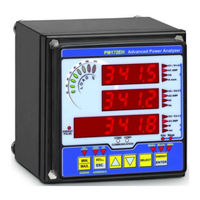
Satec PM172E Installation And Operation Manual (135 pages)
Series PM172 Powermeters
Brand:
Satec
| Category:
Measuring Instruments
| Size: 3 MB
Table of Contents
Chapter 1 General Information
6
Limited Warranty
2
Table of Contents
3
Chapter 2 Installation
10
Mechanical Installation
10
Panel Mounting
10
DIN Rail Mounting
13
Remote Display Installation
14
Mechanical Installation
14
Electrical Connection
15
Electrical Installation
17
Typical Installation
17
Terminals
18
Power Source Connection
18
Chassis Ground Connection
19
Wiring Diagrams
19
I/O Connections
24
Relay Outputs
24
Digital Inputs
24
Analog Outputs
25
Analog Inputs
25
Communications Connections
26
COM1 RS-232 Connection
26
COM1 RS-422/485 Connection
27
COM1 Dial up Modem Connection
28
COM1 Ethernet Connection
28
COM1 Profibus Connection
29
COM2 RS-422/485 Connection
30
Chapter 3 Display Operations
32
Indicators and Controls
32
Display Diagnostics
32
Numeric LED Display
32
Load Bar Graph
33
Energy Pulse LED
33
Port Activity Leds
33
Navigation Buttons
33
Data Display
33
Display Features
33
Navigation Buttons
34
Simple Reset of Accumulated Data
35
Common Measurements Display
35
Min/Max and Max. Demands Display
36
Harmonics Display
37
Energy Display
38
Status Display
39
Using the Menus
40
Navigation Buttons
40
Selecting Menus
40
Entering the Password
41
Selecting a Menu Entry
41
Viewing and Changing Setup Items
41
Menu Operations
42
Basic Device Settings
42
Device Options
43
Transformer Correction
44
Communication Ports
45
Network Address
46
Counters Setup
47
Relay Output Setup
47
Control Setpoints Setup
48
Analog Inputs Setup
49
Analog Outputs Setup
50
Analog Expander Setup
51
Timers Setup
52
Display Setup
52
Meter Security
53
Setting the Device Clock
54
Resetting Accumulators and Maximum Demands
55
Chapter 4 PAS Application Software
56
Configuration Database
56
Setting up Communications
56
Communicating through a Serial Port
57
Communicating through a Dial-Up Modem
58
Communicating through the Internet
58
Setting up the Meter
59
Downloading Setup to the Meter
59
Uploading Setup from the Meter
59
Authorization
59
Configuring Communications in Your Meter
60
Setting up Communication Ports
60
Setting up the Ethernet
61
Configuring GE EGD Production Exchanges
62
General Meter Setup
64
Basic Meter Setup
64
Device Options
65
Transformer Correction
67
Local Settings
68
Using Digital Inputs
69
Using Relay Outputs
70
Programming Analog Inputs
72
Programming Analog Outputs
73
Programming the Analog Expander
75
Using Counters
76
Using Periodic Timers
77
Using Control Setpoints
77
Configuring Summary Energy and TOU Registers
82
Setting up Total and Tariff Registers
82
Configuring the Daily Tariff Schedule
83
Configuring the Season Tariff Schedule
84
Configuring Recorders
86
Configuring Device Memory
86
Configuring the Event Recorder
87
Configuring the Data Recorder
88
Configuring the Waveform Recorder
90
Configuring Communication Protocols
93
Configuring Modbus
93
Configuring DNP3
94
Remote Device Control
99
Remote Relay Control
99
Event Flags
99
Device Diagnostics
100
Updating the Clock
101
Resetting Accumulators and Clearing Log Files
101
Administration
102
Changing a Password
102
Upgrading Device Firmware
102
Monitoring Devices
105
Viewing Real-Time Data
105
Viewing Min/Max Log
105
Viewing Real-Time Waveforms
105
Viewing Harmonic Spectrum and Synthesized Waveforms
106
Viewing Recorded Files
106
Retrieving Logs Files
106
Viewing Options
106
Viewing the Device Event Log
107
Viewing the Data Log
108
Viewing Waveforms
108
Viewing Synchronized Waveforms
113
COMTRADE and PQDIF Converters
115
Manual Converting
115
Automatic Converting
116
Appendix A Technical Specifications
117
Environmental Conditions
117
Power Supply
117
Standards Compliance
120
Appendix B Analog Output Parameters
122
Appendix C Setpoint Triggers and Actions
123
Appendix D Parameters for Data Log and Monitoring
126
Appendix E Data Scales
134
Appendix F Device Diagnostic Codes
135
Satec PM172E Quick Start Manual (15 pages)
Powermeters
Brand:
Satec
| Category:
Measuring Instruments
| Size: 0 MB
Table of Contents
Electrical Installation
5
Using the Navigation Buttons
7
Basic Setup
9
Setting the Communications
11
COM1 Settings
12
COM2 Settings
12
Input and Output Ratings
14
Advertisement
Advertisement
Related Products
Satec PM175 Series
Satec PM172P
Satec PM172EH Series
Satec PM174 Series
Satec PM172 Series
Satec PM171 series
Satec PM17X PRO Series
Satec PM130 PLUS
Satec PM130P
Satec PM130E
Satec Categories
Measuring Instruments
Cell Phone
Control Unit
Extender
Transducer
More Satec Manuals
Login
Sign In
OR
Sign in with Facebook
Sign in with Google
Upload manual
Upload from disk
Upload from URL