Sign In
Upload
Manuals
Brands
Satec Manuals
Measuring Instruments
Expertmeter PM180
Satec Expertmeter PM180 Quality Analyzer Manuals
Manuals and User Guides for Satec Expertmeter PM180 Quality Analyzer. We have
3
Satec Expertmeter PM180 Quality Analyzer manuals available for free PDF download: Reference Manual, Application Note
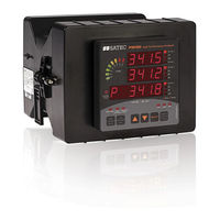
Satec Expertmeter PM180 Reference Manual (52 pages)
ExpertMeter IEC 61850 Communications Protocol High Performance Analyzer
Brand:
Satec
| Category:
Measuring Instruments
| Size: 0 MB
Table of Contents
Table of Contents
3
1 General
6
2 ACSI (Abstract Communication Service Interface) Conformance Statement
7
ACSI Basic Conformance Statement
7
ACSI Models Conformance Statement
7
ACSI Service Conformance Statement
8
3 MICS - Model Implementation Conformance Statement
11
Model Conformance
11
Common Data Attributes Classes
11
Quality
11
Analog Value
11
Configuration of Analogue Value
11
Range Configuration
11
Step Position with Transient Indication
11
Pulse Configuration
12
Originator
12
Unit Definition
12
Vector
12
Point Definition
12
Ctlmodels Definition
12
Sboclasses Definition
12
Common Data Classes
13
Single Point Status (SPS)
13
Double Point Status (DPS)
13
Integer Status (INS)
13
Protection Activation Information (ACT)
13
Directional Protection Activation Information (ACD)
13
Security Violation Counting (SEC)
13
Binary Counter Reading (BCR)
13
Measured Value (MV)
13
Complex Measured Value (CMV)
14
Sampled Value (SAV)
14
Wye
14
Delta (DEL)
14
Sequence (SEQ)
14
Harmonic Value (HMV)
14
Harmonic Value for WYE (HWYE)
14
Harmonic Value for del (HDEL)
15
Controllable Single Point (SPC)
15
Controllable Double Point (DPC)
15
Controllable Integer Status (INC)
16
Binary Controlled Step Position Information (BSC)
16
Binary Controlled Step Position Information (ISC)
16
Controllable Analog Set Point Information (APC)
16
Single Point Setting (SPG)
16
Integer Status Setting (ING)
16
Analog Setting (ASG)
16
Setting Curve (CURVE)
16
Device Name Plate (DPL)
16
Logical Node Name Plate (LPL)
16
Curve Shape Description (CSD)
17
Logical Devices and Logical Nodes
17
System Logical Nodes
17
Physical Device Information LPHD
17
Logical Node Zero LLN0
17
GOOSE Subscription Status Ctrl/Sbslgos1-Sbslgos20
17
Logical Nodes for Control
18
Switch Controllers CTRL/CSWI1- CSWI16
18
Switch Control Interlocking Status CTRL/CILO1-CILO16
18
Relay Control Interlocking Status Met1/Blkcilo1-Blkcilo8
18
Logical Nodes for Switchgear
19
Circuit Breakers CTRL/XCBR1- XCBR2
19
Circuit Switches CTRL/XSWI1- XSWI14
19
Logical Nodes for Protection Related Functions
19
Disturbance Recorders Met1/Drrdre1-Drrdre8
19
Logical Nodes for Generic Reference
20
External (GOOSE) Indication Status Ctrl/Extggio1
20
Digital Inputs Met1/Biggio1-Biggio8
20
Relay Outputs Met1/Boggio1-Boggio8
20
Event Flags Met1/Evfggio1 - Evfggio2
21
Setpoint Status Met1/Spggio1- Spggio2
21
Analog Inputs Met1/Aiggio1-Aiggio2
21
Logical Nodes for Metering and Measurement
22
Energy Counters Met1/Engmmtr1
22
Harmonic Demands Met1/Demmhai1
22
Sequence of Harmonics Met1/Hrmmhai1
22
Total Harmonics Met1/Ocvmhai1
23
3-Second Total Harmonics Met1/Osvmhai1
23
Present Demands Met1/Demmmxu1
23
Sliding Power Demands Met1/Demmmxu2
24
Accumulated Power Demands Met1/Demmmxu3
24
Predicted Power Demands Met1/Demmmxu4
25
Half-Cycle Measurements Met1/Hcvmmxu1
25
One-Second Measurements Met1/Osvmmxu1
25
Phasors Met1/Phsrmmxu1
26
Half-Cycle Sequence and Imbalance Met1/Hcvmsqi1
26
One-Cycle Imbalance Met1/Ocvmsqi1
27
Sequence Components Met1/Seqmsqi1
27
Minimum/Maximum on any Phase Met1/Ocvmsta1, Met1/Osvmsta1
27
4 PICS - Protocol Implementation Conformance Statement
29
Profile Conformance
29
A-Profile Support
29
T-Profile Support
29
MMS Conformance
29
GOOSE Conformance Statement (GOOSE Services)
31
GSSE Conformance Statement (GSSE Services)
31
SCL Services (SCL Conformance)
31
5 PIXIT - Protocol Implementation Extra Information for Testing
32
Device Configuration
32
ACSI Models
32
Association Model
32
Server Model
32
Setting Group Model
32
Dataset Model
33
Reporting Model
35
Control Model
39
GOOSE Publisher Model
39
GOOSE Subscriber Model
39
Time and Time Synchronization Model
39
File Transfer Model
40
Impact of the Device Settings
40
Logical Device Mode
40
Controls
40
Measurement Units
40
Process Measurement Limits
41
Deadbands
41
Textual Descriptions
41
6 Configuring IEC 61850
42
Licensing IEC 61850
42
Configuring IED Properties
42
Configuring Datasets
43
Configuring Report Control Blocks
45
Configuring the GOOSE Publisher
46
Configuring the GOOSE Subscriber
46
Configuring Report Deadbands
50
Generating a CID File
51
Advertisement
Satec Expertmeter PM180 Reference Manual (51 pages)
High Performance Analyzer, PLC Configurator
Brand:
Satec
| Category:
Measuring Instruments
| Size: 4 MB
Table of Contents
Table of Contents
3
1 General
5
2 Iec61131 Implementation
6
Limitations
6
Data Types
6
Built-In Functions
7
And
7
Not
7
Ge_Threshold
8
Le_Threshold
8
Ton
9
Tof
9
Function Block
9
Implemented Languages
9
Functional Block Diagram
10
Ladder Diagram
10
3 Programming Guide
13
Getting Started
13
Creating Project
13
Adding Devices
15
Device Properties
16
Main Function Block
17
Adding Function Blocks
17
Setting Function Blocks
18
Rename FB
18
Add Variables
19
Variable Properties
19
Add Work Area
23
Debug FB
23
Delete FB
24
Communication with the Device
24
Interfaces
24
Upload Configuration to the Device
26
Download Configuration from the Device
29
Functional Block Diagrams
32
Open Workspace
32
Add or Delete Variables
33
Variable Properties
34
Add Built-In Components
34
Making Connections
35
Making Time Delays
37
Programming Limits for Set Point Variables
38
Ladder Diagrams
41
Add Ladder Diagram
41
Rails
42
Contact
42
Negated Contact
42
Coil
43
Negated Coil
43
Creating LD
43
Transformation LD into Setpoints
47
Using PLC Configurator with PAS
47
4 Troubleshooting
49
Address in Not Set
49
Connection Error
49
No MAIN Module
50
Unconnected Inputs
51
Satec Expertmeter PM180 Application Note (19 pages)
High Performance Analyzer, Fault Locator
Brand:
Satec
| Category:
Measuring Instruments
| Size: 1 MB
Table of Contents
Table of Contents
3
1 General
4
Fault Locator Functionality
4
Off-Line Fault Location
4
Single-Ended Fault Location
4
Two-Ended Fault Location
4
Transformer Inaccuracies
5
2 Configuring the Device
6
Configuring the Fault Locator
6
General Parameters
6
Power Line Impedance
8
Line with Branch
8
Transformer Correction
9
Configuring the Fault Recorder
10
3 Operating the Onboard Fault Locator
12
Fault Locator Operation
12
Getting On-Line Data
12
Getting Recorded Data
13
4 Using the Off-Line Fault Locator
16
Single-Ended Fault Location
16
Two-Ended Fault Location
18
Advertisement
Advertisement
Related Products
Satec PM130 PLUS
Satec PM130P
Satec PM130E
Satec PM175 Series
Satec PM172P
Satec PM130 series
Satec PM135P
Satec PM135E
Satec PM130EH PLUS
Satec PM17X PRO Series
Satec Categories
Measuring Instruments
Cell Phone
Control Unit
Data Loggers
Gas Detectors
More Satec Manuals
Login
Sign In
OR
Sign in with Facebook
Sign in with Google
Upload manual
Upload from disk
Upload from URL