Sign In
Upload
Manuals
Brands
Rinnai Manuals
Boiler
COMBI i120C
Rinnai COMBI i120C Manuals
Manuals and User Guides for Rinnai COMBI i120C. We have
4
Rinnai COMBI i120C manuals available for free PDF download: Installation And Operation Manual, Conversion Manual, Technical Bulletin
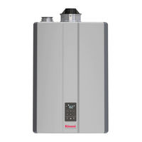
Rinnai COMBI i120C Installation And Operation Manual (137 pages)
Wall-Mounted, Gas-Fired Combi Boiler, Central Heating and Domestic Hot Water
Brand:
Rinnai
| Category:
Boiler
| Size: 14 MB
Table of Contents
Table of Contents
2
Acronyms and Abbreviations
4
Safety
4
2 Safety
5
Safety Precautions
5
Safety Symbols
5
3 About the Boiler
7
About the Boiler
7
Accessories
7
Bottom View
7
Components
7
Dimensions
7
Front View
7
Specifications
7
Bottom View
8
Bottom View Piping
8
Components
9
Specifications
10
Dimensions
11
Supply Connections
12
Accessories
13
Choose an Installation Location
14
Fill the Condensate Collector
14
Installation Guidelines
14
Items Included
14
Mount the Boiler to the Wall
14
Venting
14
What You'll Need
14
Items Needed
15
Other Items You May Need
15
Guidelines
17
Water Quality
17
Clearances
18
Environment
18
Installation Location Checklist
18
Instructions
19
Mount the Boiler to the Wall
19
Supplied by Installer
19
You will Need
19
Fill the Condensate Collector
20
PVC Venting Safety Switch
21
Termination Considerations
21
Venting Installation Sequence
21
Venting Options
21
High Temperature Vent Setting Instructions
23
Direct Vent (Concentric and Twin Pipe)
25
Non-Direct Vent (Room Air)
25
Venting Options
25
2 In. TWIN PIPE TERMINATIONS
30
Direct Vent: Concentric Pipe
34
Example Vent Applications
35
Installation Instructions
35
Maximum Equivalent Velt Length
36
Termination Clearances
36
Twin Pipe
36
Twin Pipe: Installation Instructions
37
Twin Pipe: Example Vent Applications
38
Room Air: Termination Clearances
39
Exhaust Termination Clearances for Internal Room Air Applications
40
Room Air Vertical Termination of Multiple Boilers
40
Room Air: Combustion Air
41
Vent Length Includes Additional Venting, Fittings and Terminations
41
Confined Space
42
Unconfined Space
42
Using Indoor Air for Combustion
42
Using Outdoor Air for Combustion
42
Checklist for Combustion Air and Venting Requirements
43
Location
43
Room Air: Installation
44
Room Air: Example Vent Applications
45
Connect the Gas Supply
46
Gas Operating Instructions
46
Gas Pipe Sizing Reference Tables
46
Gas Supply
46
Operating Instructions
47
To Turn off Gas to Appliance
47
Gas Pipe Sizing Calculation Worksheet
48
Gas Pipe Sizing Reference Table
48
Natural Gas
48
Propane (Undiluted)
49
7 DHW System Piping
50
DHW System Piping
50
Guidelines
50
Instructions
50
Piping Diagram for a Basic DHW Installation
50
Piping Diagram for a Basic DHW Installation
51
8 CH System Piping
52
Common CH Components
52
Connect the Condensate Drain Line
52
Connect the Pressure Relief Valves (DHW and CH)
52
Guidelines
52
Heating Return Connection
52
Hydraulic Separation
52
Instructions
52
Piping Diagram for a Basic CH System (with Hydraulic Separation)
52
Piping Diagram for a Basic CH System (Without Hydraulic Separation)
52
Common CH Components
53
CH System Common Components Diagram
54
Piping Diagram for a Basic CH System
55
Examples of Hydraulic Separation
57
Hydraulic Separation
57
Pressure Drop and Water Flow Curve with Hydraulic Separation
58
Water Flow (GPM)
58
Connect the Pressure Relief Valves
59
Connect the Condensate Drain Line
60
Condensate Pump Safety Switch Wiring
61
Condensate Pump Safety Switch Installation
62
Electrical Connections
63
Guidelines
63
Post-Power Supply Connection Checklist
63
Power Supply
63
Electrical Connections
64
Commissioning
65
Deaeration Process
65
Filling Process
65
Safety Precautions
65
Deaeration Process
66
Bypass Deaeration
67
Post-Installation Checklist
68
12 Operation
70
Basic Operation Settings
70
Control Panel
70
DHW Recirculation Function
70
Outdoor Reset Control
70
Simultaneous CH and DHW Operation
70
Start-Up Information
70
Control Panel
71
Control Panel Features
71
Display Window
72
Basic Operation Settings
73
Domestic Hot Water Setpoint Temperature
73
Central Heating Setpoint Temperature
74
Domestic Hot Water Comfort Modes
75
Control Panel Sound
76
Units of Measurement
76
Child Lock
77
Performance Data
78
Performance Data Table
79
PC Board DIP Switches
80
DIP Switch Settings
81
Altitude
82
To Change the Altitude
82
Central Heating Button
83
Pump Linkage with CH Mode on
83
Thermostat Usage (Default Setting)
83
Parameter Settings
84
Parameter Settings Table
85
Outdoor Temperature Sensor
89
Outdoor Reset Connection
90
Outdoor Reset Curve Temperature Guidelines
90
Outdoor Reset Curves
91
Select Reset Curve
92
Boost Mode
93
Maximum Outdoor Temperature
93
Crossover Mode
94
Dedicated Mode
94
DHW Recirculation Function
94
Recirculation Mode
95
To Enable Recirculation
95
Plumbing Diagram
96
Simultaneous CH and DHW Operation
98
Diagnostic Codes
100
Display Diagnostic Codes
100
Reset Diagnostic Codes
100
Maintenance
103
Forced Hi/Low Fire Modes
105
Licensed Professional Maintenance
106
Owner Maintenance
106
Test the Ignition Safety Shut off Device
106
Flush the DHW Heat Exchanger
107
Freeze Protection Operation
109
Approved System Antifreezes
111
Approved System Cleaners
111
Approved System Inhibitors
111
Flush the CH Plumbing System
112
Flush the DHW Heat Exchanger
113
14.8 CH Pressure Drop and Flow Curve
114
14.9 DHW Pressure Drop and Flow Curve
114
System Application Examples
114
Single Zone with Hydraulic Separation Plumbing
115
Two Zones with Hydraulic Separation Plumbing
116
Multiple Zones with Hydraulic Separation Plumbing
118
Multiple Zones with CH Mode Active
119
Gas Conversion
120
Items Required
120
Replace the Orifice
121
Adjust Parameter Settings
122
Check Operation
123
Check the Normal Operating Sequence
123
Visual Inspection of Flame
123
Wiring Diagram
124
Ladder Diagram
125
CH Pressure Drop and Flow Curve
126
DHW Pressure Drop and Flow Curve
127
Cable Lengths and Sizes
128
Guidelines for Additional DHW Controller
128
Connect
129
Remove a Boiler from a Common Vent System
130
Warranty
132
Advertisement
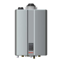
Rinnai COMBI i120C Installation And Operation Manual (136 pages)
Wall-Mounted, Gas-Fired Combi Boiler
Brand:
Rinnai
| Category:
Boiler
| Size: 12 MB
Table of Contents
Table of Contents
2
Safety Symbols
5
Front View
7
Bottom View
7
Installation Guidelines
14
What You'll Need
14
Items Included
14
Choose an Installation Location
14
Mount the Boiler to the Wall
14
Fill the Condensate Collector
14
Venting
14
Guidelines
17
Venting Installation Sequence
21
Termination Considerations
21
PVC Venting Safety Switch
21
Venting Options
21
Gas Supply
46
Connect the Gas Supply
46
Gas Operating Instructions
46
Gas Pipe Sizing Reference Tables
46
Guidelines
50
Instructions
50
Piping Diagram for a Basic DHW Installation
50
Guidelines
52
Instructions
52
Common CH Components
52
Piping Diagram for a Basic CH System (Without Hydraulic Separation)
52
Piping Diagram for a Basic CH System (with Hydraulic Separation)
52
Hydraulic Separation
52
Connect the Pressure Relief Valves (DHW and CH)
52
Connect the Condensate Drain Line
52
Condensate Pump Safety Switch Wiring
52
Electrical Connections
63
Post-Power Supply Connection Checklist
63
Safety Precautions
65
Filling Process
65
Deaeration Process
65
Start-Up Information
70
Control Panel
70
Basic Operation Settings
70
Outdoor Reset Control
70
DHW Recirculation Function
70
Simultaneous CH and DHW Operation
70
Diagnostic Codes
100
Maintenance
106
Owner Maintenance
106
Licensed Professional Maintenance
106
Test the Ignition Safety Shut off Device
106
Flush the DHW Heat Exchanger
107
Pressure Drop and Flow Curve
114
DHW Pressure Drop and Flow Curve
114
Warranty
132
Rinnai COMBI i120C Conversion Manual (24 pages)
Wall-Mounted, Gas-Fired Combi and Solo Boiler
Brand:
Rinnai
| Category:
Boiler
| Size: 3 MB
Table of Contents
English
2
Table of Contents
2
Introduction
3
Safety Symbols
3
Specifications
4
Conversion Instructions
5
Items Required
5
Replace the Orifice
6
Adjust Parameter Settings
7
Check Operation
8
Conversion Rating Plate
9
Canadian High Altitude Installation Setting Procedure
9
Operating Instructions
10
For the Consumer - Gas Conversion Information
11
French Manual
12
Français
13
Introduction
14
Symboles de Sécurité
14
Spécifications
15
Instructions Pour la Conversion
16
Articles Requis
16
Remplacement de L'orifice
17
Réglage des Paramètres
18
Vérification du Fonctionnement
19
Plaque Signalétique
20
Réglages Pour L'installation en Haute Altitude, Canada
20
Instructions D'utilisation
21
Pour Le Consommateur - Information Sur la Conversion
22
Advertisement
Rinnai COMBI i120C Technical Bulletin (5 pages)
Boiler with DHW Recirculation
Brand:
Rinnai
| Category:
Boiler
| Size: 0 MB
Table of Contents
DHW Recirculation Facts
1
Dedicated Mode
1
Crossover Mode (Factory Default)
3
Configure the Boiler for DHW Recirculation
4
Step 1: Set DIP Switches and Parameter Settings
4
Step 2: Connect Wiring to PC Board
5
Advertisement
Related Products
Rinnai SOLO i120S
Rinnai SOLO i150S
Rinnai i120CN
Rinnai COMBI i060C
Rinnai COMBI i090C
Rinnai SOLO i060S
Rinnai I090SN
Rinnai IP060160C
Rinnai IP150199C
Rinnai IP060S
Rinnai Categories
Water Heater
Indoor Fireplace
Heater
Air Conditioner
Boiler
More Rinnai Manuals
Login
Sign In
OR
Sign in with Facebook
Sign in with Google
Upload manual
Upload from disk
Upload from URL