Sign In
Upload
Manuals
Brands
OMRON Manuals
Controller
SYSMAC CJ Series
OMRON SYSMAC CJ Series Manuals
Manuals and User Guides for OMRON SYSMAC CJ Series. We have
6
OMRON SYSMAC CJ Series manuals available for free PDF download: Operation Manual, Instruction Sheet
Omron SYSMAC CJ Series Operation Manual (317 pages)
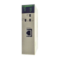
10Base-5, 10Base-T Ethernet Units
Brand:
Omron
| Category:
Network Hardware
| Size: 3 MB
Table of Contents
Table of Contents
6
Precautions
16
General Precautions
17
Intended Audience
17
Safety Precautions
17
Application Precautions
18
Operating Environment Precautions
18
Conformance to EC Directives
20
Section 1 Features and System Configuration
22
Features and System Configuration
22
Features
23
Device Configuration
24
Node Connections
24
System Configuration
24
10Base-5 Ethernet Unit
25
Devices Required in a Network
25
10Base-T Ethernet Unit
26
Related Programming Devices
27
Specifications
28
Software Configuration
31
Allocating IP Addresses
33
IP Address Configuration
33
IP Addresses
33
IP Address Settings
34
Subnet Masks
34
Ethernet and IEEE802.3 Standards
35
Installation
35
Precautions
35
Section 2 Communications Functions
36
Communications Functions
36
Communications Functions
37
Ethernet Unit Functions
38
Socket Ports Used by the Ethernet Unit
38
FINS Communications
39
Selecting Communications Services
39
Socket Services
40
FTP Server
42
Mail
42
Section 3 Installation and Initial Setup
44
Installation and Initial Setup
44
Automatic Address Generation
45
Before Operation
45
IP Address Table
46
Overview of Startup Procedure
47
Unit Components
49
Nomenclature
50
Indicators
53
CS-Series Ethernet Units
54
Switch Settings
54
CJ-Series Ethernet Units
56
Mounting to a CS-Series PC
58
Mounting to a PC
58
Mounting to a CJ-Series PC
59
Connecting to the Network
60
Ethernet Connectors
60
Ethernet Network Installation
60
Connecting the Cable
61
Connecting the Power Supply (CS1W-ETN01 Only)
63
Connecting Programming Devices to the PC
66
Creating an I/O Table
66
I/O Table Overview
66
Procedure for Creating an I/O Table
66
Creating Routing Tables
67
Routing Table Overview
67
Connecting and Using a Peripheral Device for the PC
69
CPU Bus Unit System Setup Defaults
72
System Setup
72
Using a Programming Device
72
When Settings Are Required
72
Creating an IP Address Table
73
Creating an IP Router Table
73
Checking Communications
74
Internode Test
74
PING Command
74
PING Command and Internode Testing
74
Simple Startup Test Example
75
Section 4 System Setup and Memory Allocations
78
System Setup and Memory Allocations
78
Allocated Words
79
CPU Bus Unit System Setup
80
Settings
81
Mail Settings
85
CIO Area Allocations
88
DM Area Allocations
94
Section 5 Fins Communications
100
FINS Communications
100
Communications on an Ethernet Network
101
FINS Communications Service Features
101
Overview of FINS Communications
101
Procedure before Using FINS Communications
103
Communications Specifications
104
Sending Commands from a PC
104
Program Example
113
Transmission Delays
114
Designating Remote Addresses
117
Sending Commands from a Host Computer
117
FINS Frames
118
Sample Program
120
Delays for Accessing PC Memory
122
FINS Server
123
Section 6
124
Socket Services
124
Overview
125
Socket Service Functions
125
Socket Port Numbers
126
Sockets
126
Using Sockets with the Ethernet Unit
126
Differences between TCP and UDP
127
Opening TCP Sockets
128
Fragmentation of Send Data
129
Maximum Transmission Delays
131
Precautions in Using Socket Services
132
Using Socket Services with Socket Service Request Switches
133
Socket Service Parameters
135
Response Codes
138
Socket Service Request Switches
143
UDP/TCP Socket Status
146
Application Procedure
147
Socket Services and Socket Status
148
Timing Charts
149
TCP/IP Communications Programming Example
151
UDP/IP Communications Programming Example
155
Using Socket Services with CMND(490)
160
UDP/TCP Socket Status
161
Socket Services and Socket Status
164
Communications Timing Chart
165
Socket Service Timing Chart
165
TCP/IP Communications Programming Example
167
UDP/IP Communications Programming Example
174
Section 7 Ftp Server
182
FTP Server
182
Overview
183
Setting Login Names and Passwords
184
Using File Memory
184
FTP Server Application Example
188
Table of Commands
189
Using FTP Commands
189
Using the Commands
190
Error Messages and FTP Status
193
UNIX Application Example
195
Section 8 Mail
198
Mail
198
Overview of Mail Function
199
Mail Contents
200
Mail Triggers
201
Sending Mail
201
Mail Status
202
Mail Example
203
Sending Mail
203
Testing Communications
206
Communications Testing Functions
207
PING Command
207
Internode Test
208
Section 10 Troubleshooting
212
Troubleshooting with Indicators
213
Error Log
215
Error Status
215
Error Log Error Codes
216
Startup Problems
218
Troubleshooting Procedures
218
FINS Communications Problems
219
(Send(090)/Recv(098)/Cmnd(490))
220
UDP Socket Problems
220
TCP Socket Problems
222
FTP Service Problems
223
Network Connection Problems
224
Mail Problems
226
Troubleshooting with Response Codes
228
Results Storage Area Response Codes
231
Section 11 Fins Commands Addressed to Ethernet Units
234
FINS Commands Addressed to Ethernet Units
234
Command Code List
235
Command Codes and Response Codes
235
Response Code List
235
Format
236
Socket Applications
236
PC Memory Areas
237
Command/Response Reference
238
Reset
238
Controller Data Read
239
Controller Status Read
240
Internode Echo Test
241
Broadcast Data Send
242
Broadcast Test Results Read
242
Error Log Read
242
Error Log Clear
244
Udp Open Request
244
Udp Receive Request
245
Udp Send Request
246
Udp Close Request
248
Passive Tcp Open Request
249
Active Tcp Open Request
252
Tcp Receive Request
253
Tcp Send Request
255
Tcp Close Request
256
Ping
257
Ip Address Table Write
258
Ip Address Write
259
Ip Address Table Read
260
Ip Router Table Read
261
Protocol Status Read
262
Memory Status Read
266
Socket Status Read
268
Address Information Read
269
Ip Address Read
270
Network Installation
272
Ethernet Network Parameters
282
Buffer Configuration
284
TCP Status Transitions
286
Auxiliary Area Data
288
CPU Bus Unit Allocations in the CPU Unit
290
ASCII Characters
298
Dimensions
300
Maintenance
304
J Inspections
306
Index
308
Revision History
314
Advertisement
Omron SYSMAC CJ Series Operation Manual (306 pages)
Brand:
Omron
| Category:
Industrial Equipment
| Size: 3 MB
Table of Contents
Table of Contents
11
Precautions
15
Intended Audience
15
General Precautions
15
Safety Precautions
15
Application Precautions
17
Section 1 Introduction
19
Section 1
19
Introduction
19
CX-Process Tool
20
Overview
20
Files Created with CX-Process Tool
21
Function Block Navigation and Multi-Node Folder
21
Relationships between Tag Files
25
Operating Conditions of CX-Process Tool
26
Relationship with CX-Process Monitor
27
Overview of the CX-Process Monitor and CX-Process Monitor Plus
27
Settings Required on the CX-Process Tool
28
CX-Process Tool Specifications
31
Version Improvements
34
Version 1.20
34
Version 1.50
35
Version 2.00
36
Version 2.50
37
Version 3.00
38
Version 3.1
39
Version 3.2
39
Version 4.0
40
Function Blocks/Items Incompatible with Earlier Versions
41
Incompatibility with Versions Earlier than Version 1.20
41
Incompatibility with Versions Earlier than Version 1.50
41
Incompatibility with Versions Earlier than Version 2.00
42
Function Blocks/Items Incompatible with Earlier Versions
44
Incompatibility with Versions Earlier than Version 2.50
44
Connecting to the PLC
46
Incompatibility with Versions Earlier than Version 3.2
46
Incompatibility with Versions Earlier than Version 4.0
46
Features of Finsgateway and CX-Server
47
Selecting the Communications Driver
47
Using Finsgateway
48
Connecting Cables
50
Basic Operating Procedures
51
Operations
57
Creating Function Blocks
57
Online Operations
60
Section 2 Preparations to Create Function Blocks
62
Preparations to Create Function Blocks
63
Section 2
63
Installation
63
Installing CX-Process Tool
64
Uninstalling the Previous Version of CX-Process Tool
64
Before Installing Finsgateway
66
Installing Finsgateway Embedded Version
68
Installing CX-Server
75
Overview of User Interface
76
Starting the CX-Process Tool
76
Function Block Navigation Tree
78
Function Block Navigation Menus
79
Section 3 Creating Function Blocks
103
Creating Function Blocks
105
Section 3
105
Creating Function Block
105
Data Configuration
105
Overview of Procedure for Creating Function Blocks
106
Using the CX-Process Monitor
137
Setting and Compiling Monitor Tags for CX-Process Monitor
137
Validate the Monitor Tag List
142
Using the CX-Process Monitor Plus
143
Preparations for Using SCADA Software
145
Creating SCADA Software and RS View Tag Files
145
Other Interfaces with HMI
161
User Link Tables
162
Overview
162
Creating User Link Tables
163
Importing CX-Programmer Symbols into a User Link Table
167
Creating User-Defined Blocks
171
How User-Defined Blocks Work
171
Overview
171
Creating User-Defined Blocks on the CX-Process Tool
173
Inserting User-Defined Blocks
175
Exporting User-Defined Blocks to Files
176
Importing User-Defined Blocks from Files
177
Creating Step Ladder Program Instructions
178
Ladder Diagrams
178
Mnemonics
185
Cross-Reference Display
188
Step Ladder Instructions
189
Other Icons
191
Creating Sequence Tables
192
Creating a Sequence Table
192
Names of Sequence Table Elements
194
Setting Execution Forms
194
Zooming in and out of a Sequence Table
194
Editing Sequence Tables
195
Settings for Conditions and Actions
196
Editing Elements
199
Expanding the Sequence Table
200
Displaying Loop Controller Memory Maps
201
Checking for Errors in the Sequence Table
201
Printing the Sequence Table
201
Validating the Actions of the Sequence Table
201
Displaying Loop Controller Memory Maps
202
Operation Procedure
202
Screens
202
Printing
205
Printable Data
206
Printing Function Blocks
207
Printing Block Diagrams
208
Printing Cross-References
210
Printing Ladder Diagrams
210
Printing CSV Tag Lists
211
Printing Monitor Tag Lists (Loop Control Units Only)
211
Printing All
212
Printing ITEM Lists
212
Printing Sequence Tables
212
Printing Connection Maps
213
Printing User Link Tables
213
Setting Options
214
Overview
214
General Tab Page
216
Communication Tab Page
218
CSV Tag Setting Tab Page
219
Function Block Diagram Tab Page
220
Sequence Table Tab Page
221
Step Ladder Tab Page
221
User Link Tab Page
222
Connection Map Tab Page
223
Section 4 Online Operation
224
Section 4
224
Online Operation
224
Overview of Online Functions
225
Initial Settings for Online Connections
226
Selecting the Communications Driver
226
Using Finsgateway
227
Using CX-Server
236
Peripheral Bus (Toolbus) Connections
237
Downloading, Uploading and Comparing Data
238
Downloading
240
Uploading
243
Compare
247
Run/Stop Command
251
Monitor Run Status
252
Monitoring the System Run Status
252
Items Marked "Reset
254
Items Marked "Detailed Display
254
Operation Check
256
Checking the Version
256
Monitoring ITEM Data for Selected Function Blocks
258
Downloading Individual ITEM Data Settings
258
Block Diagram Check
258
Forced Changes to Analog Output Signals
262
Ladder Diagram Operation Check
263
Validating Sequence Table Operation (LCB05/05D Only)
266
Tuning
280
Switching to the Tuning Screen
280
Data Logging on Tuning Screens
281
Screen Configuration
283
Face Plate Controls
284
Operation Procedures
288
Backup and Recovery
291
Backup Procedure
292
Backup/Recovery of Project Comments, Annotations, Tags, and Connection Data
293
Recovery Procedure
293
Clear All
296
Controlling the CPU Unit
296
Creating the I/O Tables
296
Setting the PLC Setup
296
Password Protection
297
Changing the Operating Mode of the CPU Unit
297
Online Operations for Loop Controller
297
Inputting the Password before Uploading Data
298
Section 5
299
Troubleshooting
299
Troubleshooting
300
Error Codes
300
Omron SYSMAC CJ Series Operation Manual (290 pages)
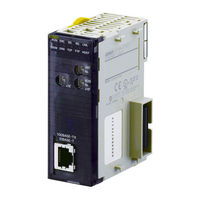
100Base-TX Ethernet Units Construction of Networks
Brand:
Omron
| Category:
Network Hardware
| Size: 3 MB
Table of Contents
Table of Contents
8
Precautions
20
General Precautions
21
Intended Audience
21
Safety Precautions
21
Application Precautions
22
Operating Environment Precautions
22
Applicable Directives
24
Concepts
24
Conformance to EC Directives
24
Section 1 Features and System Configuration
26
Features and System Configuration
26
Determining the Objectives
27
Ethernet Unit Function Guide
27
Overall System Configuration Example
27
Features
33
Devices Required for Constructing a Network
36
System Configuration
36
Setup Area and Related Peripheral Devices
37
General Specifications
39
Specifications
39
Dimensions
40
Software Configuration
41
FINS Communications Service
42
Overview of Communications Functions
42
Socket Services
43
FTP Server Function
45
Mail Send Function
45
Mail Receive Function
46
Automatic Clock Adjustment Function
47
Specifying Servers by Host Name
47
Component Names
48
Nomenclature and Functions
48
Indicators
50
Comparison with Previous Models
52
Unit Version Upgrade Information
53
Section 2 Installation and Initial Setup
54
Installation and Initial Setup
54
Overview of Startup Procedure
55
CS-Series Ethernet Units
56
Switch Settings
56
CJ-Series Ethernet Units
57
Mounting to a CJ-Series PLC
58
Mounting to a CS-Series PLC
58
Mounting to a PLC
58
Basic Installation Precautions
59
Network Installation
59
Precautions
60
Recommended Products
60
Using Contact Outputs (Common to All Units)
62
Connecting the Cable
63
Connecting to the Network
63
Ethernet Connectors
63
Connecting Programming Devices to the PLC
64
Creating I/O Tables
64
I/O Table Overview
64
Procedure for Creating I/O Tables
65
Unit Setup Procedure
66
Using the CX-Programmer
66
Using the Web Browser Setting Function
68
Basic Settings
71
Unit Setup for Particular Applications
75
Communications Test
77
PING Command
77
Ethernet Unit
78
Host Computer
78
Converting from Previous Models
79
CX-Programmer Unit Setup
86
Setup
87
Fins/Tcp
89
Dns
91
Smtp
92
Pop
93
Mail Address
94
Send Mail
95
Receive Mail
97
Auto Adjust Time
99
Http
100
Ethernet Unit Memory Allocations
102
CIO Area Allocations
103
DM Area Allocations
111
Auxiliary Area Data
115
Section 5 Determining IP Addresses
118
Determining IP Addresses
118
Allocating IP Addresses
119
IP Address Configuration
119
IP Addresses
119
Ethernet Unit IP Address Settings
120
Subnet Masks
120
IP Addresses in FINS Communications
121
Specifying Nodes in FINS Communications Services
121
Pairing Addresses in Internal Tables
123
Application Examples
130
Related Products and Communications/Setting Methods
131
Pairing IP Addresses and FINS Node Addresses
133
Private and Global Addresses
133
Using a Private Address for the Ethernet Unit
135
Ethernet Unit with a Global Address
137
Section 6 Fins Communications
140
FINS Communications
140
Communications on an Ethernet Network
141
Overview of FINS Communications
141
Using the FINS/UDP and FINS/TCP Methods
141
FINS Communications Service Specifications for Ethernet
142
FINS/UDP Method
143
Overview
143
FINS/TCP Method
145
Overview
145
Creating Routing Tables
149
Routing Table Overview
149
Connecting and Using a Peripheral Device for the PLC
150
Routing Table Setting Examples
151
CX-Programmer (CX-Server)
153
Using FINS Applications
153
Finsgateway
157
Communicating between OMRON Plcs
162
Communications Specifications
162
PLC Communications Data Areas
163
Using SEND(090), RECV(098), and CMND
164
Writing Programs
168
Program Example
172
Transmission Delays
174
Precautions on High Traffic in FINS Communications
180
Section 7 Fins Commands Addressed to Ethernet Units
182
FINS Commands Addressed to Ethernet Units
182
Command Code List
183
Command Codes and Response Codes
183
Response Code List
183
Format
184
Socket Applications
184
PLC Memory Areas
185
Command/Response Reference
186
Reset
186
Controller Data Read
187
Controller Status Read
188
Internode Echo Test
190
Broadcast Data Send
191
Broadcast Test Results Read
191
Error Log Read
192
Error Log Clear
193
Udp Open Request
194
Udp Receive Request
195
Udp Send Request
197
Udp Close Request
198
Passive Tcp Open Request
199
Active Tcp Open Request
202
Tcp Receive Request
205
Tcp Send Request
206
Tcp Close Request
208
Ping
209
Fins/Tcp Connection Remote Node Change Request
210
Fins/Tcp Connection Status Read
211
Ip Address Table Write
212
Ip Address Table Read
214
Ip Address Write
214
Ip Router Table Read
216
Protocol Status Read
217
Memory Status Read
221
Socket Status Read
223
Address Information Read
224
Ip Address Read
225
Section 8 Troubleshooting
228
Troubleshooting
228
Troubleshooting with Indicators
229
Error Status
230
Error Log
231
Error Log Error Codes
232
Startup Problems
238
Troubleshooting Procedures
238
FINS Communications Problems (SEND(090)/RECV(098)/CMND(490))
239
UDP Socket Problems
240
TCP Socket Problems
243
FTP Service Problems
246
Network Connection Problems
248
Troubleshooting with Response Codes
252
Results Storage Area Response Codes
256
Ethernet Network Parameters
260
Buffer Configuration
262
TCP Status Transitions
264
ASCII Characters
266
Maintenance
268
Inspections
270
Ethernet Unit Web Function
272
Index
278
Revision History
286
Advertisement
Omron SYSMAC CJ Series Operation Manual (318 pages)
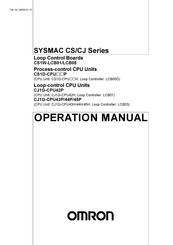
Loop Control Board
Brand:
Omron
| Category:
Controller
| Size: 5 MB
Table of Contents
Table of Contents
13
Precautions
23
General Precautions
24
Intended Audience
24
Safety Precautions
25
Operating Environment Precautions
29
Application Precautions
30
EC Directives
32
Other Applicable Directives
32
Section 1 Introduction
35
Introduction
35
Outline
36
Features
39
LCB01/05 Version 1.5 Upgrade Information
41
LCB01/05 Version 2.0 Upgrade Information
43
LCB01/03/05 Version 3.0 Upgrade Information
44
Upgraded Functions for LCB01/05 and LCB03 Version 3.5
46
Basic System Configuration
47
Upgraded Functions for LCB01/05 and LCB03 Version 3.6
47
Application Examples
48
1-1-10 Loop Controller Mechanism
51
1-1-11 Overall Mechanism of Data Exchange
55
1-1-12 Internal Mechanism of Loop Controllers
57
1-1-13 List of Function Blocks
59
1-1-14 Differences between Loop Control Units and Boards
66
1-1-15 Version Upgrade Information
70
Configuration of Instrumentation System
72
Mounting Location
72
Determining the System Configuration
74
Description of Basic System Configuration
79
General Specifications
85
Specifications
85
Function Specifications
87
Outline of PID Block Specifications
91
Software Specifications
94
How to Use Function Blocks for Specific Operations
96
Basic Procedure for Using the Loop Controller
100
Section 2 Components, Installation, and Wiring
105
Components, Installation, and Wiring
105
Names and Functions of Parts
106
Installation
108
Mountable Units
108
Mounting Procedure
108
Handling Analog Input/Output Units
109
Connecting to CX-Process Tool
110
Using Finsgateway
110
Connecting Cables
112
Using CX-Server
112
Section 3 Mechanism of the Loop Controller
115
Mechanism of the Loop Controller
115
Configuration of Function Blocks
116
Preparing Function Block Data Sheets
116
Items Common to All Function Blocks
118
Items Unique to Individual Function Blocks
119
Connecting Function Blocks
122
Description of Operation
125
When Turning the Power on to the PLC
125
Reference: Operations at Power on
133
Details of Hot Start, Cold Start and Stop State
134
Backup/Recovery Operations and Automatic Transfer of ITEM Data
137
Simple Backup of Function Block Data to a Memory Card (LCB01/03/05 Ver. 2.0)
139
Simple Backup of Function Block Data to a Memory Card (LCB01/03/05 Ver. 3.0 or Later)
144
Replacing Function Block Data in the Loop Controller (LCB01/03/05 Ver. 3.5)
150
Indicating Loop Controller Run/Stop (All Function Blocks)
152
(LCB01/03/05 Ver. 3.0 or Later)
153
Starting (RUN/STOP) PID Calculation Only for each Function Block
153
Stop each Function Block Operation and Cancel Operation-Stop
153
3-2-11 Monitoring the Run Status of Function Blocks
154
Wireless Debugging (LCB01/03/05 Ver. 3.0 or Later)
154
3-2-13 Relationship between CPU Unit States and Loop Controller States
158
3-2-14 Specifying the Operation Cycle
159
3-2-15 Conditions for Determining the Operation Cycle
161
3-2-16 Order of Operations
163
3-2-17 about the LCB Load Rate
164
3-2-18 Evaluating the LCB Load Rate at the System Design Stage
164
3-2-19 External I/O Response Cycle on the Overall System
166
Exchanging Data with the CPU Unit
170
Mutual Exchange of Run Status
170
Commands from the CPU Unit to the Loop Controller
178
Exchanging Data
179
Exchanging Data Using SCADA and Other Software
191
Exchanging Data Using SCADA, Pts, and Other Software
191
Duplex Operation of Loop Controllers
201
Loop Controller Duplex Function
201
Outline of Procedure for Using Duplex Mode
202
Restrictions on Duplex Loop Controllers
203
Fail-Safe Countermeasure Guidelines
205
Measures When the Loop Controller Has Stopped Running
205
Measures for a CPU Unit Fatal Error
207
Required Conditions for the Man-Machine Interface
207
Simple Example of Use
209
Simple Example of Use
210
Section 5 Examples of Function Block Combinations
217
Examples of Function Block Combinations
217
Basic Examples of PID Control
218
Multi-Channel PID Control
218
Simple PID Control
218
PID Control for Switching Multiple Set Points
219
PID Control for Switching PID Constants by Three Set Point Zones
220
Ramp Program Control
222
Time-Proportional Control
223
Monitoring and Accumulating Flowrate
224
Cascade Control
225
Examples of Applied Control Types
225
Feedforward Control
228
Sample PI Control
231
Dead Time Compensation
233
How to Use FINS Commands
237
How to Use FINS Commands
238
Description of FINS Commands
240
FINS Commands for Loop Controllers
240
Section 7 Errors and Alarm Troubleshooting
255
Errors and Alarm Troubleshooting
255
Errors and Alarm Troubleshooting
256
Judging Errors by Indicators
256
Errors During Initialization
258
Errors During Normal Operation
261
Error Log Data
262
Execution Error Code List
263
Maintenance
272
Replacing the Loop Control Board
272
Replacing Process-Control CPU Units
274
Replacing Loop-Control CPU Units
275
Using the Flash Memory
276
How to Use the Step Ladder Program Block
277
B How to Use the Sequence Table Block
289
Index
311
Revision History
315
OMRON SYSMAC CJ Series Operation Manual (371 pages)
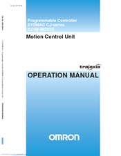
SYSMAC CJ-series Programmable Controller Motion Control Unit
Brand:
OMRON
| Category:
Controller
| Size: 4 MB
Table of Contents
Table of Contents
5
Precautions
7
Intended Audience
7
General Precautions
7
Safety Precautions
7
Operating Environment Precautions
8
Application Precautions
9
Conformance to EC Directives
11
Section 1
13
Introduction
13
Overview
13
System Philosophy
14
Motion Control Concepts
16
Servo System Principles
25
Trajexia System Architecture
28
Cycle Time
29
Program Control and Multi-Tasking
34
Motion Sequence and Axes
35
Motion Buffers
43
Mechanical System
45
Axis Numbers
46
Section 2
47
Installation and Wiring
47
Unit Components
47
Wiring
52
Installation
62
Specifications
67
Section 3
71
Data Exchange
71
Introduction
71
Memory Areas
72
Data
74
FINS Commands
77
Section 4
85
BASIC Commands
85
Categories
85
All BASIC Commands
96
Section 5
277
Examples
277
How-To's
278
Practical Examples
332
Section 6
359
Troubleshooting
359
Items to Check First
360
Error Indicators
361
Troubleshooting Errors
362
Miscellaneous
368
Revision History
369
Omron SYSMAC CJ Series Instruction Sheet (4 pages)
Terminal Block Conversion Unit
Brand:
Omron
| Category:
Controller
| Size: 0 MB
Advertisement
Related Products
Omron Sysmac CJ Series
Omron SYSMAC CJ1W-MCH72
Omron Sysmac CPM2C
Omron SYSMAC CQM1
Omron SYSMAC CS Series
Omron SYSMAC C series
Omron SYSMAC CV Series
Omron SYSMAC CS-series
Omron SYSMAC CS1H
Omron SYSMAC CJ1W-ETN21
OMRON Categories
Blood Pressure Monitor
Controller
Accessories
Switch
Inverter
More OMRON Manuals
Login
Sign In
OR
Sign in with Facebook
Sign in with Google
Upload manual
Upload from disk
Upload from URL