Sign In
Upload
Manuals
Brands
Nalco Manuals
Water System
3D TRASAR Series
Nalco 3D TRASAR Series Manuals
Manuals and User Guides for Nalco 3D TRASAR Series. We have
1
Nalco 3D TRASAR Series manual available for free PDF download: Installation And Operation Manual
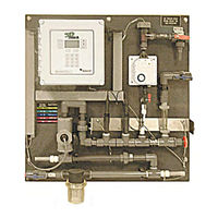
Nalco 3D TRASAR Series Installation And Operation Manual (243 pages)
Brand:
Nalco
| Category:
Water System
| Size: 7.85 MB
Table of Contents
Table of Contents
3
Section 1: Introduction
9
About the 3D TRASAR ® 5500
9
About this Manual
9
TRASAR 3500 and 3D TRASAR 5500 Overview
11
How the 3D TRASAR 5500 System Works
12
Fluorometer
12
TRASAR Scale Control, 3D TRASAR Bio-Control, & NCM Corrosion Technology
12
Data Storage / Reporting and Communications
13
Safety
14
Section 2: Installation and Start-Up
15
Identify Hardware Model
16
STEP 1 - Unpack and Identify
16
Pre-Installed Items (All Models)
18
Pre-Installed Items (3D TRASAR 5500 Models Only)
18
Items Requiring Assembly (All Models)
18
Items Requiring Assembly (3D TRASAR 5500 Models Only)
18
Pellet Feeder Assembly (Optional)
19
Items Shipped Separately
19
5A 3D TRASAR Starter Upgrades
19
5B 3D TRASAR Start-Up and Maintenance Kits
19
STEP 2 - Mount the Controller
20
General Instructions
20
TRASAR Controller Dimensions
21
Wall Mounting Templates
25
Frame Mount Template
28
STEP 3 - Install Bio-Reporter Feeder
29
Install Bio-Reporter Pellet Feeder
29
Install Liquid Bio-Reporter Pump
31
STEP 4 - Plumb Controller
32
Sample Point Selection
32
Chemical Feed Pumps
35
Typical Installation Drawing
36
STEP 5 - Plumb Bio-Reporter Feeder
37
Pellet Feeder Plumbing
37
Pellet Feeder Best Practices
38
Liquid Bio-Reporter Plumbing
38
STEP 6 - Install Probes
39
Fluorometer Installation
40
Ph Probe Installation
41
ORP Probe Installation
42
Conductivity Probe Installation
43
NCM Corrosion Probe Installation
44
STEP 7 - Wiring
46
General Information
46
Controller Box Layout
47
Controller Wiring Details
48
Junction Box Layout
50
System Power Connections
52
Internal Power Connections
52
Control Relay Connections - Powered (120 VAC Fused @ 2.5 Amps)
53
Control Relay Connections - Non-Powered (Fused @ 2.5 Amps)
54
Control Relay Connections - Termination Details
55
Pellet Feeder Connections
57
System Probe Connections
57
Analog I/O Connections
59
Factory Wired Digital Inputs
60
User Wired Digital Inputs
60
Alarm Output Connections
61
Phone Line Connections
61
SCADA Connections (Modbus RTU)
62
Nalco Global Gateway
62
LAN Connections
62
Ethernet (Direct Connect to 3D TRASAR 5500)
62
STEP 8 - Calibration & System Checkout
63
Establish Sample Flow & Apply Power
63
Calibrate Probes
64
Checkout Control Relays
65
STEP 9 - Start-Up System
66
Section 3: 3D TRASAR Configurator
67
PC System Requirements
67
Installing the Software
67
Configurator Support
68
Sample Help Screen
68
Sample Search Screen
68
The Keys
69
TRASAR 3500 and 5500 Control Unit Overview
69
Section 4: Controller Settings
69
The Display Panel
69
The Graphical Icons
70
Menu, Information, Actions and Alarms Flow Diagram
71
The Menu Key
72
Password Screen
72
Control Settings Submenu
72
Background Correction Screen
73
Blowdown Screen
74
Ph Screen
74
Oxidizing Biocide Screen
74
Tagged Polymer (Relay 2) Product Screen
74
TRASAR (Relay 1) Product Screen
74
Alarm Settings Submenu
75
System Alarms Screen
75
Control Alarms Screens
75
Performance Alarms Screen
75
Relay Alarms Screens
76
Ma Alarm Screen
76
Preferences Submenu
77
Network Submenu
78
System Information Submenu
78
The Information Key
79
System Performance Screens
79
Product Usage Screens
80
Operating Data Screens
80
Water and Energy Screens
81
Plot Data Screens
81
Control Methods Screens
82
Timer Status Screens
83
External Inputs Screens
83
Product Factors Screen
83
Diagnostic Data Screen
84
The Actions Key
85
Password Screen
86
Clean and Calibrate Screen
86
Fluorometer Calibration Screens
87
Ph Calibration Screens
88
ORP Calibration Screens
89
Conductivity Calibration Screens
90
Probe Calibration / Maintenance List
93
Manual Relay Control Screens
94
Pumping Rates Screens
95
Slug Feed Biocide Screens
96
System Startup Screens
97
Test Email Screen
97
Service Email Screen
97
The Alarms Key
98
Sensor Alarms
98
System Alarms
98
Control Alarms
99
Communication Errors
99
Performance Alarms
99
Relay Timeout Alarms
100
Analog Alarms
100
Failsafe Mode
100
Startup Mode
100
Section 5: 3D TRASAR Scale Control
101
Nalco Scale Index (NSI) Measurement
101
TRASAR Scale Blowdown Control - Uses NSI to Adjust the Blowdown Setpoint
101
TRASAR Scale Tagged Polymer Control - Uses NSI to Adjust the Tagged Polymer Setpoint
101
TRASAR Scale Blowdown Control
102
TRASAR Scale Blowdown Control: 1-Drum Program Overview
102
Start-Up Procedure for 1-Drum 3D TRASAR Scale Blowdown Control
103
TRASAR Scale Blowndown Control: 2-Drum Program Overview
105
Start-Up Procedure for 2-Drum 3D TRASAR Scale Blowdown Control
106
TRASAR Scale Tagged Polymer Control
109
TRASAR Scale Tagged Polymer Control: 2-Drum Program Overview
109
Start-Up Procedure for 2-Drum 3D TRASAR Scale Tagged Polymer Control
110
TRASAR Scale Control - Frequently Asked Questions
113
Nalco Bio-Index Measurement (NBI)
123
Oxidizing Biocide Application and Slug Feeds
123
TRASAR Bio-Control and Overlaid Ox Slugs
124
TRASAR Bio-Shock Mode
125
Ox-Slug/Shock Control Settings
125
TRASAR Bio-Control/3D TRASAR Bio-Shock Start-Up Procedure
126
Bio-Reporter Selection
126
Pellet Feeder Operation
129
Filling the Pellet Feeder
130
Bio-Reporter Initial System Dosing
131
Pellet Feeder Cleaning
132
Pellet Feeder Maintenance
132
Cleaning Pellet Feeder Exit Tube
133
Tighten Valve Seat
134
Pellet Shield Replacement
136
SCADA Systems
162
TRASAR 5500 Controller
162
TRASAR Configurator
162
TRASAR Optimizer
162
Section 7: Communication and Data Management
162
TRASAR Web
163
TRASAR Web Set up
163
Create/Edit Users
164
Assign Controllers (Data Sources)
165
Manage Controller (Data Source) Setup Information
166
TRASAR Web Data
167
TRASAR Web Alarms
169
Vantage V100
170
Import 3D TRASAR Data into Vantage V100
170
Vantage V100 3D TRASAR EZ Reports
172
Nalco Global Gateway
176
Maintenance Schedule
177
Section 8: Maintenance
177
Clean Fluorometer Flow Cell
178
Check/Replace Fluorometer Desiccant
178
Check Sensor Calibration
178
Probe Replacement Schedule
179
Cleaning Basket / Wye Strainer
179
Pellet Feeder Maintenance
179
Check / Refill Pellet Feeder
179
Section 9: Troubleshooting
180
General Troubleshooting
180
Alarm Screen Troubleshooting
186
Register Definitions (Coils, Floats, Words, and Longs)
214
Control Relay 1 - TRASAR 00000
216
Control Relay 2 - TAG POLYMER 00000
216
Control Relay 3 - BIO-REPORTER 00000
216
Control Relay 4 - OXID BIOCIDE 00000
216
Control Relay 5 - NONOX BIOCIDE 00000
217
Control Relay 6 - BLOWDOWN 00000
217
Digital in 1 - no Flow 000013
217
Digital in 2 - Interlock 000014
217
Digital in 3 - Spare 000015
217
Product 1 Dosage (TRASAR) 3000
217
Product 2 Dosage (TAG Polymer) 3000
217
Corrosion 1 (Right Side of Controller) 3000
218
Polymer Consumption 3000
218
Sample Temperature 3000
218
Analog Input 2
219
Advertisement
Advertisement
Related Products
Nalco 3D TRASAR 3500 Series
Nalco 3D TRASAR 060-TR3501.88
Nalco 3D TRASAR 060-TR3510.88
Nalco 3D TRASAR 060-TR3511.88
Nalco 3D TRASAR 060-TR3520.88
Nalco 3D TRASAR 060-TR3521.88
Nalco 3D TRASAR 060-TR3522.88
Nalco 3D TRASAR 060-TR3523.88
Nalco 3D TRASAR 060-TR3530.88
Nalco 3D TRASAR 060-TR3531.88
Nalco Categories
Measuring Instruments
Water System
More Nalco Manuals
Login
Sign In
OR
Sign in with Facebook
Sign in with Google
Upload manual
Upload from disk
Upload from URL