Sign In
Upload
Manuals
Brands
MKS Manuals
Accessories
HPS 937A Series
MKS HPS 937A Series Manuals
Manuals and User Guides for MKS HPS 937A Series. We have
2
MKS HPS 937A Series manuals available for free PDF download: Operation And Maintenance Manual, Owner's Operation And Maintenance Manual
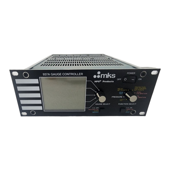
MKS HPS 937A Series Owner's Operation And Maintenance Manual (108 pages)
High Vacuum Multi-Sensor System
Brand:
MKS
| Category:
Accessories
| Size: 2 MB
Table of Contents
Table of Contents
5
Table Ofcontents
9
Package Contents
9
Safety Information
10
Symbols
10
Symbols Used in this Manual (English)
10
Symboles Utilisés Dans Ce Manuel (Français)
10
In dieser Betriebsanleitung Vorkommende Symbole (Deutsch)
11
Símbolos Usados en el Manual (Español)
11
Symbol Definitions
12
Definition of Symbols Found on the Unit (English)
12
Définition des Symboles Apparaissant Sur L'appareil (Français)
12
Definitionen der am Gerät Angebrachten Symbole (Deutsch)
13
Símbolos que Aparecen en la Unidad (Español)
13
Safety Precautions
14
Safety Procedures and Precautions (English)
14
Sicherheitsvorschriften und Vorsichtsmaßnahmen (Deutsch)
18
Procedimientos y Precauciones de Seguridad (Español)
20
Specifications
22
Controller
22
Sensors
25
Feature and Control Locations
30
Typical Applications for the Series 937A
32
HPS™ Products Series 937A Multi-Sensor High
33
Vacuum System
33
Set Points
34
Leak Test
34
Analog Output Signals
34
Computer Interface
34
Setting up the Series 937A Controller
35
Removing a Module
35
Configuring a Module
35
Sensor Modules
35
Cold Cathode
36
Pirani
36
Convection Pirani
37
Capacitance Manometer
37
Thermocouple
38
Analog Module
38
Pressure Units - Switches 1 and 2
38
Control/Combination Sensor Channels- Switches 3 and 4
38
Line Frequency - Switch 5
39
Cold Cathode Sensor Delay - Switch 6
39
Configuration-Switch 7
39
UCAL Enable/Disable
39
RS-232/RS-485 Communications Module (Optional)
39
Power Supply Module
41
Installing a Module
41
Panel Labels
42
Mounting the Controller
42
AC Power Cord
43
Operating the Series 937A Controller
44
Power
44
Display
44
Using the Front Panel Controls
46
Using Function Select
47
Display Test Mode
47
Reviewing Controller Setup
47
Setup Review Screen 1
47
Cold Cathode Non-Standard Configuration Codes
48
Setup Review Screen 2
49
Setup Review Screen 3
49
Setup Review Screen 4
50
Setup Review Screen 5
50
Setup Review Screen 6
50
Setup Review Screen 7
51
Pressure Mode
51
Cold Cathode Sensor High Voltage
52
Front Panel Control Lock
52
Leak Test Mode
53
Relay Set Points Mode
54
Reading a Relay Set Point
54
Setting a Relay Set Point
54
Disabling a Relay Set Point
55
Relay Inductive Loads and Arc Suppression
55
Protection and Control Set Points Mode
56
Setting a Protection Set Point
56
Setting a Control Set Point
56
Protection and Control Set Point Display Messages
57
Protection and Control Set Point Messages
57
Disabling a Protection or Control Set Point
58
Zero and ATM Calibration Modes
58
Zero Calibration Mode
59
Capacitance Manometer Auto-Zero Feature
60
ATM Calibration Mode
61
Calibrating the Convection Pirani Sensor for Atmosphere
62
Method 1
62
Method 2
62
Cold Cathode Operation
63
C.C. On/C.C. off Front Panel Push-Buttons
64
Cold Cathode Module Remote Connector
64
Analog Module
64
Communications Module (Optional)
64
Using Protection and Control Set Points
65
Determining Protection and Control Set Points
66
Information Update Rate
67
Controller Analog Output
68
Buffered Output
68
Logarithmic Output
69
Combination Logarithmic Output
70
Error Messages
71
Main Program Checksum Test
71
Communications Module Program Checksum Test
71
Nonvolatile Memory Error in Correction Factors
71
Setup Error
72
Quick Reference Tables
73
Relay Setpoints
74
Control Setpoints
74
Protection Setpoint
74
Spare Parts and Accessories
75
Product Warranty
78
Notes
79
Appendix A: Installing a Series 937A Sensor
80
General
80
Managing Contamination in a Cold Cathode Sensor
81
Testing a Cold Cathode Sensor
81
Series 423 I-MAG Cold Cathode Sensor
81
Connecting the I-MAG Sensor
81
Disassembling the I-MAG Sensor
81
Cleaning the I-MAG Sensor
82
Assembling the I-MAG Sensor
84
Preparing the Sensor for Bakeout
85
Series 421 Cold Cathode Sensor
85
Connecting the Series 421 Sensor
85
Disassembling the Series 421 Sensor
85
Cleaning the Series 421 Sensor
87
Assembling the Series 421 Sensor
88
Preparing the Sensor for Bakeout
88
Pirani Sensors
88
General
88
Locating a Pirani Sensor
88
Preventing Contamination in a Pirani Sensor
89
Series 315/345 Pirani Sensor
89
Orienting the Series 315/345 Pirani Sensor
89
Connecting the Series 315/345 Sensor
89
Cleaning the Series 315/345 Sensor
91
Testing the Series 315/345 Sensor
91
Series 317 Convection Pirani Sensor
91
Orienting the Series 317 Sensor
91
Connecting the Series 317 Sensor
92
Cleaning the Series 317 Sensor
94
Testing the Series 317 Sensor
94
Preparing the 317 Sensor for Bakeout
94
Capacitance Manometer MKS Baratron
95
General
95
Installing the Baratron Capacitance Manometer
95
Connecting the Baratron™ Capacitance Manometer
95
Repairing the Baratron™ Capacitance Manometer
96
Thermocouple Sensor
97
General
97
Connecting the DV-6M Sensor
97
Cleaning the DV-6M Sensor
98
Appendix B: Leak Testing with the Series 937A
99
Appendix C: 937A Sensor Output Vs. Pressure Curves
101
Buffered Analog Output Cold Cathode (Series 421 and 423)
101
Buffered Analog Output Pirani (Series 315 and 345)
102
Buffered Analog Output Convection Pirani (Series 317)
103
Buffered Analog Output Capacitance Manometer
104
Buffered Analog Output Thermocouple (DV-6M)
105
Logarithmic and Combination Output All Sensors
106
Advertisement
MKS HPS 937A Series Operation And Maintenance Manual (110 pages)
High Vacuum Multi-Sensor System
Brand:
MKS
| Category:
Security Sensors
| Size: 24 MB
Table of Contents
Table of Contents
6
Package Contents
10
Safety Information
11
Symbols
11
Symbols Used in this Manual (English)
11
Symboles Utilisés Dans Ce Manuel (Français)
11
In dieser Betriebsanleitung Vorkommende Symbole (Deutsch)
12
Símbolos Usados en el Manual (Español)
12
Symbol Definitions
13
Definition of Symbols Found on the Unit (English)
13
Définition des Symboles Apparaissant Sur L'appareil (Français)
13
Definitionen der am Gerät Angebrachten Symbole (Deutsch)
14
Símbolos que Aparecen en la Unidad (Español)
14
Safety Precautions
15
Safety Procedures and Precautions (English)
15
Sicherheitsvorschriften und Vorsichtsmaßnahmen (Deutsch)
19
Procedimientos y Precauciones de Seguridad (Español)
21
Specifications
23
Controller
23
Sensors
26
Feature and Control Locations
31
Typical Applications for the Series 937A
33
HPS™ Products Series 937A Multi-Sensor High
34
Vacuum System
34
Set Points
35
Leak Test
35
Analog Output Signals
35
Computer Interface
35
Setting up the Series 937A Controller
36
Removing a Module
36
Configuring a Module
36
Sensor Modules
36
Cold Cathode
37
Pirani
37
Convection Pirani
38
Capacitance Manometer
38
Thermocouple
39
Analog Module
39
Pressure Units - Switches 1 and 2
39
Control/Combination Sensor Channels- Switches 3 and 4
39
Line Frequency - Switch 5
40
Cold Cathode Sensor Delay - Switch 6
40
Configuration-Switch 7
40
UCAL Enable/Disable
40
RS-232/RS-485 Communications Module (Optional)
40
Power Supply Module
42
Installing a Module
42
Panel Labels
43
Mounting the Controller
43
AC Power Cord
44
Operating the Series 937A Controller
45
Power
45
Display
45
Using the Front Panel Controls
47
Using Function Select
48
Display Test Mode
48
Reviewing Controller Setup
48
Setup Review Screen 1
48
Cold Cathode Non-Standard Configuration Codes
49
Setup Review Screen 2
50
Setup Review Screen 3
50
Setup Review Screen 4
51
Setup Review Screen 5
51
Setup Review Screen 6
51
Setup Review Screen 7
52
Pressure Mode
52
Cold Cathode Sensor High Voltage
53
Front Panel Control Lock
53
Leak Test Mode
54
Relay Set Points Mode
55
Reading a Relay Set Point
55
Setting a Relay Set Point
55
Disabling a Relay Set Point
56
Relay Inductive Loads and Arc Suppression
56
Protection and Control Set Points Mode
57
Setting a Protection Set Point
57
Setting a Control Set Point
57
Protection and Control Set Point Display Messages
58
Protection and Control Set Point Messages
58
Disabling a Protection or Control Set Point
59
Zero and ATM Calibration Modes
59
Zero Calibration Mode
60
Capacitance Manometer Auto-Zero Feature
61
ATM Calibration Mode
62
Calibrating the Convection Pirani Sensor for Atmosphere
63
Method 1
63
Method 2
63
Cold Cathode Operation
64
C.C. On/C.C. off Front Panel Push-Buttons
65
Cold Cathode Module Remote Connector
65
Analog Module
65
Communications Module (Optional)
65
Using Protection and Control Set Points
66
Determining Protection and Control Set Points
67
Information Update Rate
68
Controller Analog Output
69
Buffered Output
69
Logarithmic Output
70
Combination Logarithmic Output
71
Error Messages
72
Main Program Checksum Test
72
Communications Module Program Checksum Test
72
Nonvolatile Memory Error in Correction Factors
72
Setup Error
73
Quick Reference Tables
74
Relay Setpoints
75
Control Setpoints
75
Protection Setpoint
75
Spare Parts and Accessories
76
Warranty
79
Notes
80
Appendix A: Installing a Series 937A Sensor
81
General
81
Managing Contamination in a Cold Cathode Sensor
82
Testing a Cold Cathode Sensor
82
Series 423 I-MAG Cold Cathode Sensor
82
Connecting the I-MAG Sensor
82
Disassembling the I-MAG Sensor
82
Cleaning the I-MAG Sensor
83
Assembling the I-MAG Sensor
85
Preparing the Sensor for Bakeout
86
Series 421 Cold Cathode Sensor
86
Connecting the Series 421 Sensor
86
Cleaning the Series 421 Sensor
88
Assembling the Series 421 Sensor
89
Preparing the Sensor for Bakeout
89
Pirani Sensors
89
General
89
Locating a Pirani Sensor
89
Preventing Contamination in a Pirani Sensor
90
Series 315/345 Pirani Sensor
90
Orienting the Series 315/345 Pirani Sensor
90
Connecting the Series 315/345 Sensor
90
Cleaning the Series 315/345 Sensor
92
Testing the Series 315/345 Sensor
92
Series 317 Convection Pirani Sensor
92
Orienting the Series 317 Sensor
92
Connecting the Series 317 Sensor
93
Cleaning the Series 317 Sensor
95
Testing the Series 317 Sensor
95
Preparing the 317 Sensor for Bakeout
95
Capacitance Manometer MKS Baratron
96
General
96
Installing the Baratron Capacitance Manometer
96
Connecting the Baratron™ Capacitance Manometer
96
Repairing the Baratron™ Capacitance Manometer
97
Thermocouple Sensor
98
General
98
Connecting the DV-6M Sensor
98
Cleaning the DV-6M Sensor
99
Appendix B: Leak Testing with the Series 937A
100
Appendix C: 937A Sensor Output Vs. Pressure Curves
102
Buffered Analog Output Cold Cathode (Series 421 and 423)
102
Buffered Analog Output Pirani (Series 315 and 345)
103
Buffered Analog Output Convection Pirani (Series 317)
104
Buffered Analog Output Capacitance Manometer
105
Buffered Analog Output Thermocouple (DV-6M)
106
Logarithmic and Combination Output All Sensors
107
Advertisement
Related Products
MKS HPS 917
MKS HPS 903 Series
MKS HPS
MKS HPS Square Body LoPro Series
MKS HPS 145 Vacuum Sentry Series
MKS HPS 945 Series
MKS HPS 919 Series
MKS HPS 947 Series
MKS HPS 937 Series
MKS HPS 937
MKS Categories
Controller
Measuring Instruments
Transducer
Control Unit
Industrial Equipment
More MKS Manuals
Login
Sign In
OR
Sign in with Facebook
Sign in with Google
Upload manual
Upload from disk
Upload from URL