Sign In
Upload
Manuals
Brands
Mitsubishi Electric Manuals
Amplifier
Melservo MR-J3- 350B4
Mitsubishi Electric Melservo MR-J3- 350B4 Manuals
Manuals and User Guides for Mitsubishi Electric Melservo MR-J3- 350B4. We have
1
Mitsubishi Electric Melservo MR-J3- 350B4 manual available for free PDF download: Instruction Manual
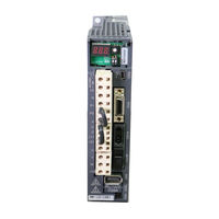
Mitsubishi Electric Melservo MR-J3- 350B4 Instruction Manual (408 pages)
Melservo J3 Series General-Purpose AC Servo SSCNET Compatible
Brand:
Mitsubishi Electric
| Category:
Amplifier
| Size: 17.73 MB
Table of Contents
2
Safety Instructions
16
Table of Contents
22
Functions and Configuration
22
Introduction
23
Function Block Diagram
23
Servo Amplifier
26
Servo Amplifier Standard Specifications
28
Function List
29
Model Code Definition
31
Combination with Servo Motor
32
Structure
32
Parts Identification
32
Connector
39
Removal and Reinstallation of the
42
Configuration Including Auxiliary Equipment
50
Installation
50
Installation Direction and Clearances
52
Keep Out Foreign Materials
52
Cable Stress
53
SSCNET Cable Laying
55
Inspection Items
55
Parts Having Service Lives
56
Signals and Wiring
57
Input Power Supply Circuit
65
I/O Signal Connection Example
67
Explanation of Power Supply System
67
Signal Explanations
68
Power-On Sequence
69
CNP1, CNP2, CNP3 Wiring Method
78
Connectors and Signal Arrangements
79
Signal (Device) Explanations
82
Alarm Occurrence Timing Chart
83
Interfaces
83
Internal Connection Diagram
84
Detailed Description of Interfaces
86
Source I/O Interfaces
87
Treatment of Cable Shield External Conductor
88
SSCNET Cable Connection
90
Connection of Servo Amplifier and Servo Motor
90
Connection Instructions
91
Power Supply Cable Wiring Diagrams
101
Servo Motor with Electromagnetic Brake
101
Safety Precautions
102
Timing Charts
104
Wiring Diagrams (HF-MP Series HF-KP Series Servo Motor)
105
Grounding
106
Control Axis Selection
108
Switching Power On for the First Time
108
Startup Procedure
109
Wiring Check
110
Surrounding Environment
111
Start Up
112
Servo Amplifier Display
114
Test Operation
114
4.3 Servo Amplifier Display
115
Test Operation Mode
115
Test Operation Mode in MR Configurator
117
Motorless Operation in Controller
118
Basic Setting Parameters (No.pa )
118
Parameter List
119
5.1 Basic Setting Parameters (No.pa)
119
Parameter Write Inhibit
120
Selection of Regenerative Option
121
Using Absolute Position Detection System
121
Forced Stop Input Selection
122
Auto Tuning
123
In-Position Range
124
Selection of Servo Motor Rotation Direction
124
Encoder Output Pulse
126
Gain/Filter Parameters (No. PB )
126
Parameter List
127
Detail List
134
5.4 I/O Setting Parameters (No. PD)
134
Extension Setting Parameters (No. PC )
134
Parameter List
135
List of Details
138
Analog Monitor
140
Alarm History Clear
141
5.2 Gain/Filter Parameters (No. PB)
141
I/O Setting Parameters (No. PD )
141
Parameter List
142
List of Details
144
Different Adjustment Methods
144
Adjustment On a Single Servo Amplifier
145
Adjustment Using MR Configurator
146
Auto Tuning Mode
147
Auto Tuning Mode Operation
148
Adjustment Procedure By Auto Tuning
149
Response Level Setting in Auto Tuning Mode
150
Manual Mode 1 (Simple Manual Adjustment)
154
Interpolation Mode
155
Differences Between Melservo-J2-Super and MELSERVO-J3 in Auto Tuning
156
Adaptive Filter
156
Function Block Diagram
159
Machine Resonance Suppression Filter
161
Advanced Vibration Suppression Control
165
Low-Pass Filter
165
Gain Changing Function
165
Applications
166
Function Block Diagram
167
Parameters
169
Gain Changing Operation
172
Troubleshooting
172
Alarms and Warning List
173
Remedies for Alarms
174
Troubleshooting
179
Remedies for Warnings
182
Outline Drawings
194
Characteristics
194
Overload Protection Characteristics
196
Power Supply Equipment Capacity and Generated Loss
199
Dynamic Brake Characteristics
199
Dynamic Brake Operation
201
The Dynamic Brake at the Load Inertia Moment
202
Cable Flexing Life
203
Inrush Currents at Power-On of Main Circuit and Control Circuit
204
11 Options and Auxiliary Equipment
204
Cable/Connector Sets
205
Combinations of Cable/Connector Sets
211
Encoder Cable/Connector Sets
220
Motor Power Supply Cables
221
Motor Brake Cables
222
SSCNET Cable
224
Regenerative Options
234
Options
237
FR-BU2-(H) Brake Unit
238
Brake Unit Parameter Setting
238
Selection
239
Connection Example
246
Outline Dimension Drawings
248
Power Regeneration Converter
251
Power Regeneration Common Converter
259
External Dynamic Brake
264
Junction Terminal Block PS7DW-20V14B-F (Recommended)
266
MR Configurator
267
Battery MR-J3BAT
268
Heat Sink Outside Mounting Attachment (MR-J3ACN)
270
Recommended Wires
274
No-Fuse Breakers, Fuses, Magnetic Contactors
274
Power Factor Improving DC Reactor
276
Power Factor Improving AC Reactors
277
Relays (Recommended)
278
Surge Absorbers (Recommended)
278
Noise Reduction Techniques
283
Line Noise Filter (FR-BLF)
285
Leakage Current Breaker
287
EMC Filter (Recommended)
292
12 Absolute Position Detection System
292
Features
293
Specifications
294
Battery Installation Procedure
296
Confirmation of Absolute Position Detection Data
298
Functions and Menus
299
Function Block Diagram
301
Packing List
302
Standard Specifications
305
Model Definition
306
Combinations of Converter Units, Drive Unit and Servo Motors
307
Parts Identification
310
Removal and Reinstallation of the Terminal Block Cover
316
Servo System with Auxiliary Equipment
317
Installation
318
Installation Direction and Clearances
319
Inspection
320
Signals and Wiring
321
Magnetic Contactor Control Connector (CNP1)
323
Input Power Supply Circuit
328
Terminal
329
How to Use the Connection Bars
330
Connectors and Signal Arrangements
332
Converter Unit Signal (Device) Explanations
334
Timing Chart
342
Servo Motor Side Details
344
Display Section and Operation Section of the Converter Unit
349
Parameter Mode
350
Parameters for Converter Unit
350
Parameter List
351
List of Details
352
Converter Unit
352
Troubleshooting
359
Outline Drawings
362
Overload Protection Characteristics
363
Power Supply Equipment Capacity and Generated Loss
364
Dynamic Brake Characteristics
366
Inrush Currents at Power-On of Main Circuit and Control Circuit
367
Options
374
External Dynamic Brake
377
Recommended Wires
378
No-Fuse Breakers, Fuses, Magnetic Contactors
379
Power Factor Improving DC Reactor
381
Leakage Current Breaker
383
EMC Filter (Recommended)
385
FR-BU2-(H) Brake Unit
398
Appendix
398
App 1. Parameter List
400
App 2. Signal Layout Recording Paper
400
App 3. Twin Type Connector : Outline Drawing for 721-2105/026-000(WAGO)
401
App 4. Change of Connector Sets to the Rohs Compatible Products
Advertisement
Share and save
Advertisement
Related Products
Mitsubishi Electric Melservo MR-J3-350B
Mitsubishi Electric Melservo MR-J3-A
Mitsubishi Electric Melservo MR-J3-10B
Mitsubishi Electric Melservo MR-J3-40B
Mitsubishi Electric Melservo MR-J3-60B
Mitsubishi Electric Melservo MR-J3-11KB
Mitsubishi Electric Melservo MR-J3-10B1
Mitsubishi Electric Melservo MR-J3-60B4
Mitsubishi Electric Melservo MR-J3-200B4
Mitsubishi Electric Melservo MR-J3-500B4
Mitsubishi Electric Categories
Air Conditioner
Controller
Projector
Inverter
Monitor
More Mitsubishi Electric Manuals
Login
Sign In
OR
Sign in with Facebook
Sign in with Google
Upload manual
Upload from disk
Upload from URL