Sign In
Upload
Manuals
Brands
Mitsubishi Electric Manuals
Controller
MELSEC iQ-F FX5S
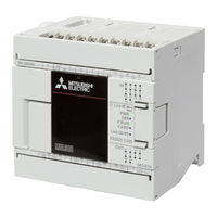
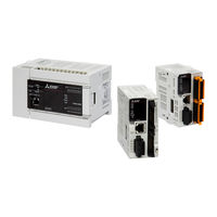
Mitsubishi Electric MELSEC iQ-F FX5S Manuals
Manuals and User Guides for Mitsubishi Electric MELSEC iQ-F FX5S. We have
6
Mitsubishi Electric MELSEC iQ-F FX5S manuals available for free PDF download: User Manual, Handbook, Manual, Quick Connection Manual
Mitsubishi Electric MELSEC iQ-F FX5S User Manual (988 pages)
Brand:
Mitsubishi Electric
| Category:
Controller
| Size: 13 MB
Table of Contents
Safety Precautions
3
Introduction
10
Table of Contents
11
Relevant Manuals
25
Terms
25
Generic Terms and Abbreviations
26
Part 1 Programming
27
Chapter 1 Program Execution
28
Scan Configuration
28
Initial Processing and Initialization Processing in RUN Mode
28
I/O Refresh
29
Program Operations
29
END Processing
29
Scan Time
29
Initial Scan Time
30
Program Execution Sequence
30
Execution Type of Program
31
Initial Execution Type Program
31
Scan Execution Type Program
32
Fixed Scan Execution Type Program
32
Displayed Items
36
Event Execution Type Program
36
Trigger Type
36
Elapsed Time
38
Trigger Setting
38
Stand-By Type Program
39
How to Execute
39
Program Type
40
Subroutine Program
40
Interrupt Program
41
Chapter 2 Processing of Operations According to Cpu Module Operation Status
46
Chapter 3 Cpu Module Memory Configuration
48
Memory Configuration
48
Data Memory
48
Device/Label Memory
49
Signal Flow Memory
49
Temporary Area
50
Sd Memory Card
51
Program Capacity Setting
51
Files
52
File Type and Storage Destination Memory
52
Executable File Operations
53
Memory Operation
54
Initialization and Value Clear
54
Chapter 4 Devices
55
List of Devices
55
User Devices
56
Input (X)
56
Output (Y)
56
Internal Relay (M)
57
Latch Relay (L)
57
Link Relay (B)
57
Annunciator (F)
57
Link Special Relay (SB)
59
Step Relay (S)
59
Timer (T/ST)
59
Details on Timer Operation and Timer Accuracy
61
Counter (C/LC)
62
Counter Type
62
Counter Reset
63
Data Register (D)
64
Link Register (W)
64
Link Special Register (SW)
64
System Devices
64
Special Relay (SM)
64
Special Register (SD)
65
Module Access Device
65
Specification Method
65
Processing Speed
65
Index Register (Z/LZ)
66
Types of Index Registers
66
Device for Which Index Modification Can be Performed
66
Index Register Setting
67
File Register (R/ER)
67
Types of File Register
67
Extended File Register (ER) Function
68
Nesting (N)
72
Pointer (P)
72
Global Pointers
73
Label Assignment Pointers
73
Interrupt Pointer (I)
73
Interrupt Causes of the Interrupt Pointer Numbers
74
The Priority for the Interrupt Pointer Numbers and Interrupt Factors
74
SFC Devices
75
SFC Block Device (BL)
75
SFC Transition Device (TR)
75
Indirect Specification
75
Constant
76
Decimal Constant (K)
76
Hexadecimal Constant (H)
76
Real Constant (E)
76
Character String Constant
77
Initial Device Value Setting
77
Setting Initial Device Values
78
Applicable Devices
78
Chapter 5 Labels
79
Chapter 6 Capacity Setting of each Area in Device/Label Memory
81
Default Capacity of each Area
81
The Setting Range of the Capacity of each Area
81
Device/Label Memory Area Setting
82
Displayed Items
82
Device Setting
83
Range of Use of Device Points
84
Chapter 7 Device/Label Access Service Processing Setting
85
Part 2 Cpu Module Built-In Functions
87
Chapter 8 Function List
89
Chapter 9 Firmware Update Function
91
Update Using an SD Memory Card
91
CPU Module Firmware Update
92
Update Using the Engineering Tool
97
CPU Module Firmware Update
97
Connection Via Hub
98
Usb Connection
98
Updating the Firmware for the Intelligent Function Module
102
Direct Connection
103
Chapter 10 Online Change
108
Online Ladder Block Change
108
Editable Contents
108
Range Changeable in a Single Session
108
Online Ladder Block Change During the Boot Operation
108
Precautions
108
Chapter 11 Interrupt Function
111
Multiple Interrupt Function
111
Interrupt Priority
111
Displayed Items
112
Input Interrupt Delay Function
113
Delay Time Setting
113
Delay Execution of the Interrupt Program
114
Chapter 12 Scan Monitoring Function
116
Scan Time Monitoring Time Setting
116
Resetting of the Watchdog Timer
116
Precautions
117
Watchdog Timer Reset When Executing a Program Repeatedly
117
Scan Time When the WDT Instruction Is Used
117
Chapter 13 Constant Scan
118
Constant Scan Settings
118
Chapter 14 Remote Operation
120
Remote RUN/STOP
120
Applications of Remote RUN/STOP
120
Operation During Remote RUN/STOP
120
Method of Execution of Remote RUN/STOP
120
Remote PAUSE
122
Application of Remote PAUSE
122
Method of Execution of Remote PAUSE
122
Remote RESET
123
Application of Remote RESET
123
Enabling Remote RESET
123
Method of Execution of Remote RESET
123
Relationship between Remote Operation and RUN/STOP Status of the CPU Module
124
14.4 Relationship between Remote Operation and CPU Module
124
Chapter 15 Latch Function
125
Types of Latch
125
Device/Label that Can be Latched
125
Latch Settings
126
Setting Latch on Devices
126
Setting Latch on Labels
127
Clearing of Data of the Latch Range
128
Precautions
128
Chapter 16 Ras Functions
129
Self-Diagnostics Function
129
Self-Diagnostics Timing
129
Check Method of Error
129
CPU Module Operation Upon Error Detection Setting
130
LED Display Setting
131
Error Clear
131
Event History Function
132
Event History Settings
133
Logging of the Event History
133
Storage Memory
134
Viewing the Event History
136
Clearing the Event History
136
Precautions
136
Chapter 17 External Input/Output Forced On/Off Function
137
Engineering Tool
140
Special Register
140
Chapter 18 Clock Function
143
Time Setting
143
Clock Data
143
Changing the Clock Data
143
Reading Clock Data
144
Using Instructions
144
Precautions
144
Setting Time Zone
145
System Clock
146
Special Relay Used for System Clock
146
Special Register Used for System Clock
146
Chapter 19 Security Functions
147
Chapter 20 Data Logging Function
149
Application Example
150
Continuous Logging
150
Trigger Logging
150
Specifications List
151
Procedure for Using
152
Devices and Software to be Used
152
Usage Flow
152
Setting Example
153
Programs Example
155
Operating Procedure
155
Setting Parameters
155
Writing the Data Logging Setting
159
Saving Data Logging Files
161
Data Logging Execution by Special Relay
164
Details of Specifications
165
Logging Type
165
Number of Records
167
Data Collection Conditions
167
Each Scanning Cycle
167
Time Specification
168
Condition Specification
168
Target Data
169
Number of Data Points
169
Trigger Condition
170
When Trigger Instruction Executed
171
Data Logging File
171
CSV File Format
172
Binary File Format
174
Saving and File Switching
177
Switching to a Storage File
179
Operation Example
179
Amount of Internal Buffer Consumed
182
Data Logging File Transfer Function (FTP Server Auto Transfer)
183
File Transfer Test
186
Setting the Operation at the Time of Transition to RUN
190
Precautions
191
Missing Data
191
Data Logging Function Processing Time
191
Errors Generated During Data Logging
192
Ethernet Communication
195
SD Memory Card Life and Replacement
196
SD Memory Card Life
196
SD Memory Card Replacement
197
Chapter 21 Memory Dump Function
199
Object Data
200
Data to be Collected
200
Trigger Condition
200
Device Specification
201
At the Occurrence of an Error
201
Combining Trigger Conditions
202
Procedure for Memory Dump
203
Flow of Data Collection
203
Effect on the Scan Time
203
Memory Dump File
204
Save File Name
204
States of the Memory Dump Function
204
Memory Dump Status
204
Sizes of Files Used for the Memory Dump Function
205
Capacity of the Memory Dump Setting File
205
Capacity of the Memory Dump File
205
Special Relay and Special Register Used in the Memory Dump Function
206
Precautions for the Memory Dump Function
206
Chapter 22 Internal Buffer Capacity Setting
208
Displayed Items
208
Chapter 23 Data Backup/Restoration Function
210
Backup Data
211
Back up File
212
Backup Function
214
Backup Processing Triggered by Turning on SM1351 (Normal Mode)
215
Operating Procedure
216
Backup Processing Triggered by Turning on SM1351 (CPU Module Auto Exchange Function)
216
Checking Backup Errors
217
Precautions
217
Restoration Function
219
Restoration Processing Triggered by Turning on SM1354
221
Automatic Restoration Using SD955
222
Restoration Triggered by CPU Module Auto Exchange
223
Checking Restoration Errors
223
Precautions
224
Chapter 24 Real-Time Monitor Function
228
Chapter 25 Memory Card Function
230
SD Memory Card Forced Stop
230
Boot Operation
232
Boot Operation Procedure
232
Specifiable File Types
232
Configuring the Boot Setting
232
Operation When Security Functions Are Enabled
233
When a File Password Is Set
233
Chapter 26 High-Speed Input/Output Function
234
High-Speed Counter Function
234
High-Speed Counter Function Overview
234
High-Speed Counter Function Execution Procedure
236
High-Speed Counter Specifications
236
Internal Clock
238
Maximum Frequency
239
Assignment for High-Speed Counters
240
Input Assignment for High-Speed Counters
240
High-Speed Counter Parameters
247
High-Speed Counter (Normal Mode)
248
Cpu Module
248
Displayed Items
248
High-Speed Counter (Pulse Density Measurement Mode)
251
Other Precautions
253
High-Speed Counter (Rotational Speed Measurement Mode)
253
Rotational Speed
255
High-Speed Comparison Table
256
Multiple Point Output, High-Speed Comparison Tables
259
Word Output
260
Processing Order
261
High-Speed Comparison Match Starts
262
System Configuration Example
262
Parameter Setting Example
262
High-Speed Counter
262
Operation Example
263
Special Relay Details
264
Special Register Details
273
Description of Operation
277
Special Relays/Special Registers Capable of High-Speed Transfers with the HCMOV/DHCMOV Instruction
282
Precautions When Using High-Speed Counters
285
FX3-Compatible High-Speed Counter Function
292
FX3-Compatible High-Speed Counter Function Overview
292
How to Start/Stop the High-Speed Counter Using the LC Device
292
Operation Example
293
The Elements of the Composition of the LC Device
293
The Comparison between the UDCNTF Instruction and HIOEN/DHIOEN Instruction
293
Assignment for FX3-Compatible High-Speed Counters
295
FX3-Compatible High-Speed Counter Setting
297
FX3-Compatible High-Speed Counter
297
Special Relays/Lc Devices Capable of High-Speed Transfers with the HCMOV/DHCMOV Instruction
299
Precautions When Using FX3-Compatible High-Speed Counters
300
Pulse Width Measurement Function
301
Pulse Width Measurement Function Overview
301
Pulse Width Measurement Specifications
301
Pulse Measurement Function Execution Procedure
304
Pulse Width Measurement Parameters
304
Details of Special Relays/Special Registers
305
Measurement Mode
307
Cautions When Using the Pulse Width Measurement Function
310
Examples of Program
310
Outline of Operation
310
Operation Diagram
311
Pulse Catch Function
312
Outline of Pulse Catch Function
312
Specifications of Pulse Catch Function
312
Pulse Catch Function Execution Procedure
313
Pulse Catch Parameters
313
Displayed Items
314
Operation of Pulse Catch Function
315
Cautions When Using the Pulse Catch Function
316
FX3-Compatible Pulse Catch Function
317
Outline of FX3-Compatible Pulse Catch Function
317
Specifications of FX3-Compatible Pulse Catch Function
317
FX3-Compatible Pulse Catch Function Execution Procedure
318
FX3-Compatible Pulse Catch Parameters
318
Operation of FX3-Compatible Pulse Catch Function
319
Cautions When Using the FX3-Compatible Pulse Catch Function
319
General-Purpose Input Functions
320
Outline of General-Purpose Input Functions
320
Specifications of General-Purpose Inputs
320
General-Purpose Input Function Parameters
322
PWM Function
323
Outline of PWM Output
323
PWM Output Specifications
323
PWM Output Function Execution Procedure
326
PWM Output Parameters
326
Details of Special Relays/Special Registers
329
Operation Monitor
329
Pulse Width
331
Cautions When Using the PWM Function
332
Examples of Program
333
Part 3 Positioning Functions
335
Chapter 27 Outline
336
Features
336
Setup Procedure for Positioning Control
337
Chapter 28 Function List
338
Chapter 29 Specifications
340
Performance Specifications
340
Input Specifications
342
Input Assignment
345
Cpu Module
345
Output Specifications
347
Assignment of Output Numbers
350
Chapter 30 Positioning Control Function
352
List of Control Functions
352
OPR Control
353
Mechanical OPR
353
High-Speed OPR
353
Positioning Control
354
1-Speed Positioning
354
Multi-Speed Operation
355
Interrupt Stop
355
Interrupt 1-Speed Positioning
356
Interrupt 2-Speed Positioning
357
Variable Speed Operation
358
Simple Linear Interpolation Operation (2-Axis Simultaneous Start)
359
Auxiliary Function
360
Dog Search Function
360
Dwell Time
362
OPR Zero Signal Count
362
Forward Limit and Reverse Limit
363
Positioning Address Change During Positioning Operation
363
Command Speed Change During Positioning Operation
364
Pulse Decelerate and Stop
365
Remaining Distance Operation
366
Multiple Axes Simultaneous Activation
367
Detection of Absolute Position
367
All Module Reset When a Stop Error Occurs
367
Chapter 31 Positioning Parameter
368
Setting Method
368
Special Device
368
Basic Setting
369
Input Check
372
Output Check
373
Details of Parameters
374
Common Item
374
Pulse Output Mode
374
Output Device
375
Unit Setting
377
Items Related to Speed
379
Max. Speed
381
Acceleration Time
382
Deceleration Time
382
Items Related to Positioning Address
382
Items Related to Operating Command
385
Items Related to Pulse y Output Instruction
390
Items Related to OPR
391
Creep Speed
393
Items Related to Table Operation
397
Items Related to Monitor
402
Chapter 32 Positioning Instruction
406
Common Items
406
Operand Specification Method
406
Start Speed
406
Pulse Output Stop
408
Operation at an Error or Abnormal End
409
Caution
409
Pulse y Output
409
Processing Details
411
Related Devices
412
Special Relays
412
Special Registers
412
Outline of Operation
413
Program Example
415
Mechanical OPR
415
Related Devices
417
Outline of Operation
420
Basic Operation
420
Program Example
423
Caution
424
Relative Positioning
425
Specification
427
Related Devices
428
Special Relays
428
Outline of Operation
430
Program Example
433
Absolute Positioning
435
Related Devices
438
Outline of Operation
440
Program Example
442
Interrupt 1-Speed Positioning
444
Related Devices
446
Outline of Operation
448
Program Example
451
Caution
453
Variable Speed Operation
454
Related Devices
456
Outline of Operation
458
Program Example
461
Caution
462
Single-Table Operation
463
Related Devices
464
Special Registers
464
Outline of Operation
465
Program Example
466
Multiple-Table Operation
472
Related Devices
473
Outline of Operation
474
Program Example
475
Multiple-Axis Table Operation
480
Related Devices
481
Special Relays
481
Outline of Operation
482
Program Example
484
Absolute Position Detection System
487
Related Devices
487
Outline of Operation
488
Program Example
489
Caution
490
Chapter 33 Table Operation
491
How to Use the Positioning Table
491
Operations of Control Method
494
No Positioning
494
Speed Positioning (Relative Address Specification)
495
Speed Positioning (Absolute Address Specification)
497
Interrupt 1 Speed Positioning
499
Variable Speed Operation
502
Interrupt Stop (Relative Address Specification)
506
Interrupt Stop (Absolute Address Specification)
509
Condition Jump
511
Interpolation Operation (Relative Address Specification)
513
Interpolation Operation (Relative Address Specification Target Axis)
517
Interpolation Operation (Absolute Address Specification)
518
Interpolation Operation (Absolute Address Specification Target Axis)
522
How to Execute Multiple Tables
523
Stepping Operation
523
Continuous Operation
525
Chapter 34 Programming
528
Cautions for Program Creation
528
Positioning Instruction Activation Timing
529
Correction of Backlash
532
Program Example
533
Operation Chart
533
Jog Operation
534
Input/Output Assignment
535
Parameter Setting
536
Setting Data
536
Forward/Reverse Rotation Program
537
FX3 Compatible SM/SD
540
Chapter 35 Troubleshooting
541
LED Status During Pulse Output and Rotation Direction Output
541
Servo Motor, Stepping Motor
542
35.3 Stop Position
543
Part 4 Analog Functions
545
Advertisement
Mitsubishi Electric MELSEC iQ-F FX5S User Manual (282 pages)
programmable
Brand:
Mitsubishi Electric
| Category:
Controller
| Size: 7 MB
Table of Contents
Safety Precautions
3
Précautions de Sécurité
12
Introduction
22
Table of Contents
23
Relevant Manuals
28
Generic Terms and Abbreviations
29
Terms
29
Chapter 1 Module Features
31
Chapter 2 System Configuration
34
Overall Configuration
34
Configuration Device List
35
MELSEC Iq-F
36
FX3 Extension Module
41
System Configuration Specifications
42
Number of Connected Extension Devices (FX5S CPU Module)
43
Number of Connected Extension Devices (FX5UJ CPU Module)
44
Number of Connected Extension Devices (FX5U CPU Module)
46
Number of Connected Extension Devices (FX5UC CPU Module)
48
Modules with Restrictions
50
Number of I/O Points
53
Current Consumption
57
Numbers and Assignment in System
61
Module Input/Output Number
61
Module Number of Extension Modules
61
Precautions
62
Selection of Input/Output Type
62
Precautions for Operating Ambient Temperature
62
Chapter 3 Part Names
64
CPU Module
64
FX5S CPU Module
64
FX5UJ CPU Module
67
FX5U CPU Module
70
FX5UC CPU Module
73
I/O Module
76
Input Module, Output Module, I/O Module
76
Powered Input/Output Module
78
High-Speed Pulse Input/Output Module
79
Extension Power Supply Module
80
Connector Conversion Module
82
SD Memory Card Module
83
SD Memory Card
83
Chapter 4 General Specifications
84
Chapter 5 Cpu Module Performance Specifications
86
CPU and Memory Specifications
86
Number of Device Points
88
Power Supply Specifications
89
AC Power Supply
89
DC Power Supply
91
Input Specifications
92
Output Specifications
96
Input/Output Derating Curve
100
Built-In Analog Specifications
101
Positioning Specifications
101
Communication Specifications
101
Built-In Ethernet Communication
101
Built-In RS-485 Communication
101
Terminal Layout
102
Built-In Analog Terminal
102
Built-In Ethernet Connector
102
Built-In RS-485 Terminal
102
Power, Input/Output Terminal Block
103
External Dimensions
111
Chapter 6 I/O Module Performance Specifications
117
Input Module
117
Extension Cable Type
117
Extension Connector Type
119
Output Module
121
Extension Cable Type
121
Extension Connector Type
123
I/O Module
125
Extension Cable Type
125
Extension Connector Type
128
Powered I/O Module
131
Extension Cable Type
131
High-Speed Pulse Input/Output Module
134
Extension Cable Type
134
External Dimensions
136
Chapter 7 Extension Power Supply Module Performance Specifications
139
Performance Specifications
139
External Dimensions
140
Chapter 8 Connector Conversion Module Performance Specifications
141
Specifications
141
External Dimensions
141
Chapter 9 Sd Memory Card Performance Specifications
143
Handling of the SD Memory Card
143
Formatting
143
Chapter 10 Battery Performance Specifications
145
Battery Application
145
Battery Life
145
Chapter 11 Function List
147
Chapter 12 Installation
149
Installation Positions
149
Installation Positions in a Control Panel
149
Layout in Control Panel
150
Installation Methods
151
Preparation for Installation
152
Installing on DIN Rail
153
Installing Directly
154
Method for Connection of Extension Devices
156
Connection of an Expansion Board (Communication Board)
156
Connection of an Expansion Board (SD Memory Card Module)
157
Connection of an Expansion Adapter
158
Connection of an Extension Module (Extension Cable Type)
159
Connection of an Extension Module (Extension Connector Type)
160
Connection of an Extended Extension Cable and Connector Conversion Adapter
161
Connection of an FX3 Extension Module
161
Chapter 13 Wiring
162
Wiring Procedure
162
Preparation of Wiring Components
163
Power Cables
163
Connector
164
Screw Terminal Block
166
European-Type Terminal Block
168
Spring Clamp Terminal Block
170
Grounding
173
Power Supply Wiring
174
AC Power Supply Wiring
174
DC Power Supply Wiring
176
Input Wiring
177
24VDC Input (Sink and Source Input Type)
177
Input Wiring Example
184
Input Wiring Examples of Terminal Blocks
191
Output Wiring
193
Relay Output
193
Transistor Output
196
Triac Output
200
Output Wiring Example
202
Output Wiring Examples of Terminal Blocks
208
Wiring Examples for Various Uses
212
Positioning Function
212
Communication Function
212
High-Speed Counter
213
Interruption
219
Digital Switch
222
Input Matrix
226
Seven Segment with Latch
228
Mitsubishi Electric MELSEC iQ-F FX5S Handbook (178 pages)
Brand:
Mitsubishi Electric
| Category:
Controller
| Size: 4 MB
Table of Contents
Safety Precautions
3
Introduction
10
Table of Contents
11
Relevant Manuals
14
Terms
15
Generic Terms and Abbreviations
15
Generic Term/Abbreviation
16
Chapter 1 Outline
17
Outline of the MELSEC Iq-F Series
17
Outstanding Performance
17
Superior Drive Control
17
Improved Programming Environment
18
Substitute Models
18
Selection and Replacement of the Models
19
Selection Table
19
Chapter 2 Replacement from Fx3G to Fx5S
20
Outline
20
Points to Consider
20
Replacement Procedure
20
Selection of Substitute Models
21
Recommended Substitute Models
21
Expansion Board
23
Expansion Adapter
23
Precautions Regarding the Hardware
24
External Dimensions
25
Conversion of the Projects
27
Operation Method for Replacing Projects
27
Operating Procedure
28
Precautions When Converting the Projects
30
Precautions When Replacing the Parameters
30
Precautions When Replacing Other Functions
31
Changing the Program
32
Replacement of the PLC
36
Specifications Comparison
36
Chapter 3 Replacement from Fx3Ge to Fx5S
38
Outline
38
Points to Consider
38
Replacement Procedure
38
Selection of Substitute Models
39
Recommended Substitute Models
39
Expansion Adapter
41
Precautions Regarding the Hardware
42
External Dimensions
43
3.4 Replacement of the PLC
44
Chapter 4 Replacement from Fx3G to Fx5Uj
45
Outline
45
Replacement Procedure
45
Selection of Substitute Models
46
Recommended Substitute Models
46
Precautions Regarding the Hardware
50
Conversion of the Projects
53
Operation Method for Replacing Projects
53
Operating Procedure
54
Precautions When Converting the Projects
56
Precautions When Replacing the Parameters
56
Precautions When Replacing Other Functions
57
Replacement of the PLC
61
Specifications Comparison
61
Chapter 5 Replacement from Fx3Gc to Fx5Uc
63
Outline
63
Points to Consider
63
Replacement Procedure
63
Selection of Substitute Models
64
Recommended Substitute Models
64
Expansion Adapter
66
Precautions Regarding the Hardware
67
External Dimensions
68
Conversion of the Projects
70
Operation Method for Replacing Projects
70
Operating Procedure
71
Precautions When Converting the Projects
73
Precautions When Replacing the Parameters
73
Precautions When Replacing Other Functions
74
Replacement of the PLC
77
Chapter 6 Replacement from Fx3Ge to Fx5Uj
78
Outline
78
Points to Consider
78
Replacement Procedure
78
Selection of Substitute Models
79
Recommended Substitute Models
79
Expansion Board
81
Expansion Adapter
82
Precautions Regarding the Hardwarel
83
External Dimensions
84
Replacement of the PLC
86
Chapter 7 Replacement from Fx3U to Fx5Uj
87
Outline
87
Replacement Procedure
87
Selection of Substitute Models
88
Recommended Substitute Models
88
Special Notes
88
Precautions Regarding the Hardware
93
Tightening Torque
94
Conversion of the Projects
96
Operation Method for Replacing Projects
96
Operating Procedure
97
Precautions When Converting the Projects
99
Precautions When Replacing the Parameters
99
Precautions When Replacing Other Functions
99
Changing the Program
100
Advertisement
Mitsubishi Electric MELSEC iQ-F FX5S Manual (46 pages)
Programmable Controller FX5 Analog Input Module/Output Module/ Multiple Input Module Function Block Reference
Brand:
Mitsubishi Electric
| Category:
Controller
| Size: 1 MB
Table of Contents
Safety Precautions
3
Introduction
4
Table of Contents
6
Relevant Manuals
8
Terms
8
Generic Terms and Abbreviations
9
Chapter 1 Overview
10
Function Block (FB) List
10
How to Obtain
10
System Configuration
11
Chapter 2 Analog Input Module, Multiple Input Module Fb
13
M+Model_Requestsetting (Validation of Settings)
13
Overview
13
Labels
13
FB Details
14
Parameter Setting
15
Performance Value
15
Error Code
15
M+Model_Operateerror (Error Operation)
16
Overview
16
Labels
16
FB Details
17
Parameter Setting
18
Performance Value
18
Error Code
18
M+Model_Setloggingparam (Logging Function Setting)
19
Overview
19
Labels
19
FB Details
21
Parameter Setting
22
Performance Value
23
Error Code
23
Chapter 3 Analog Output Module Fb
24
M+FX5-4Da_Requestsetting (Validation of Settings)
24
Overview
24
Labels
24
FB Details
24
Parameter Setting
25
Performance Value
26
Error Code
26
M+FX5-4Da_Operateerror (Error Operation)
27
Overview
27
Labels
27
FB Details
28
Parameter Setting
29
Performance Value
29
Error Code
29
M+FX5-4Da_Waveoutputsetting (Waveform Output Setting)
30
Overview
30
Labels
30
FB Details
31
Parameter Setting
33
Example of Use
33
Performance Value
35
Error Code
35
M+FX5-4Da_Waveoutputreqsetting (Waveform Output Operation)
36
Overview
36
Labels
36
FB Details
37
Parameter Setting
38
Example of Use
38
Performance Value
39
Error Code
39
Instruction Index
41
Revisions
43
Trademarks
44
Mitsubishi Electric MELSEC iQ-F FX5S Manual (36 pages)
Brand:
Mitsubishi Electric
| Category:
Controller
| Size: 0 MB
Table of Contents
Safety Precautions
3
Introduction
4
Table of Contents
5
Generic Terms and Abbreviations
6
Relevant Manuals
6
Terms
6
Chapter 1 Overview
7
Features
7
List of FB Libraries
7
System Configuration
7
Chapter 2 Specifications
9
FB Library Specifications
9
List of Structures
10
Precautions
11
Chapter 3 Details of Fb Libraries
12
M+Strprocessing_Jsondeserialize_F (Acquisition of JSON String)
12
Overview
12
Labels
12
Function Details
13
Parameter Settings
16
Performance Values
16
Error Code
17
M+Strprocessing_Jsonserialize_F (Construction of JSON String)
18
Overview
18
Labels
18
Function Details
19
Parameter Settings
22
Performance Values
22
Error Code
23
Chapter 4 Application Example
24
Acquiring Value String from JSON String
24
Overview
24
Process Flow
25
Programming
27
Constructing the JSON String
28
Overview
28
Process Flow
28
Programming
29
Instruction Index
31
Revisions
33
Trademarks
34
Mitsubishi Electric MELSEC iQ-F FX5S Quick Connection Manual (14 pages)
Programmable Controller
Brand:
Mitsubishi Electric
| Category:
Controller
| Size: 0 MB
Table of Contents
Introduction
2
Table of Contents
3
Contents
3
Relevant Manuals
4
Overview
5
Applicable Devices
5
System Configuration
6
Settings for the Kv-8000
7
Parameter Setting
7
Settings for the Fx5U
9
Parameter Setting
9
Operation Check
11
Operation Example
11
Check Method
11
Revisions
13
Warranty
13
Trademarks
13
Advertisement
Related Products
Mitsubishi Electric MELSEC iQ-F FX5
Mitsubishi Electric MELSEC iQ-F FX5UC-96MT/D
Mitsubishi Electric MELSEC iQ-F FX5UC-64MT/DSS
Mitsubishi Electric MELSEC iQ-F FX5UC-32MT/D
Mitsubishi Electric MELSEC iQ-F FX5UC-32MT/DS-TS
Mitsubishi Electric FX5-DP-M
Mitsubishi Electric Melsec iQ-F FX5-C32ET/DS-TS
Mitsubishi Electric Melsec iQ-F FX5-C32ET/DSS-TS
Mitsubishi Electric MELSEC iQ-F FX5UJ
Mitsubishi Electric FX5U-32MR/ES
Mitsubishi Electric Categories
Air Conditioner
Controller
Projector
Inverter
Heat Pump
More Mitsubishi Electric Manuals
Login
Sign In
OR
Sign in with Facebook
Sign in with Google
Upload manual
Upload from disk
Upload from URL