Sign In
Upload
Manuals
Brands
Mitsubishi Electric Manuals
Air Conditioner
FR-A720-02150-NA
Mitsubishi Electric FR-A720-02150-NA Manuals
Manuals and User Guides for Mitsubishi Electric FR-A720-02150-NA. We have
3
Mitsubishi Electric FR-A720-02150-NA manuals available for free PDF download: Instruction Manual
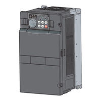
Mitsubishi Electric FR-A720-02150-NA Instruction Manual (506 pages)
Brand:
Mitsubishi Electric
| Category:
Inverter
| Size: 18 MB
Table of Contents
Table of Contents
4
Product Checking and Parts Identification
13
Inverter and Peripheral Devices
14
Peripheral Devices
15
Method of Removal and Reinstallation of the
17
Installation of the Inverter and Enclosure Design
19
Inverter Installation Environment
19
Cooling System Types for Inverter Enclosure
21
Inverter Placement
21
Wiring
24
Wiring
25
Terminal Connection Diagram
25
EMC Filter
26
Main Circuit Terminal Specifications
27
Specification of Main Circuit Terminal
27
Terminal Arrangement of the Main Circuit Terminal, Power Supply and the Motor Wiring
28
Cables and Wiring Length
31
When Connecting the Control Circuit and the Main Circuit Separately to the Power Supply
35
Control Circuit Specifications
37
Control Circuit Terminals
37
Changing the Control Logic
40
Wiring of Control Circuit
42
Wiring Instructions
43
Mounting the Operation Panel (FR-DU07) on the Enclosure Surface
44
Communication Operation
44
Connection of Motor with Encoder (Vector Control)
45
Connection of Stand-Alone Option Units
52
Connection of the Dedicated External Brake Resistor (FR-ABR)
52
Connection of the Brake Unit (FR-BU2)
54
Connection of the Brake Unit (FR-BU/MT-BU5)
56
Connection of the Brake Unit (BU Type)
58
Connection of the High Power Factor Converter (FR-HC/MT-HC)
58
Connection of the Power Regeneration Common Converter (FR-CV)
60
Connection of Power Regeneration Converter (MT-RC)
61
Connection of the Power Factor Improving DC Reactor (FR-HEL)
61
Precautions for Use of the Inverter
62
EMC and Leakage Currents
63
Leakage Currents and Countermeasures
63
EMC Measures
65
Power Supply Harmonics
67
Installation of a Reactor
68
Power-Off and Magnetic Contactor (MC)
69
Inverter-Driven 400V Class Motor
70
Precautions for Use of the Inverter
71
Failsafe of the System Which Uses the Inverter
73
Parameters
76
Operation Panel (FR-DU07)
77
Parts of the Operation Panel (FR-DU07)
77
Basic Operation (Factory Setting)
78
Changing the Parameter Setting Value
79
Displaying the Set Frequency
79
Parameter List
80
Control Mode
98
What Is Vector Control
99
Change the Control Method (Pr. 80, Pr. 81, Pr. 451, Pr. 800)
102
Speed Control by Real Sensorless Vector Control, Vector Control
106
Setting Procedure of Real Sensorless Vector Control (Speed Control)
108
Setting Procedure of Vector Control (Speed Control)
109
Torque Limit Level Setting for Speed Control (Pr. 22, Pr. 157, Pr. 803, Pr. 810 to Pr. 817, Pr. 858, Pr. 868, Pr. 874)
110
To Perform High Accuracy/Fast Response Operation (Gain Adjustment of Real Sensorless Vector Control and Vector Control) (Pr. 818 to Pr. 821, Pr. 830, Pr. 831, Pr. 880)
115
Speed Feed Forward Control, Model Adaptive Speed Control (Pr. 828, Pr. 877 to Pr. 881)
122
Torque Biases (Pr. 840 to Pr. 848)
124
Prevent the Motor from Overrunning (Pr. 285, Pr. 853, Pr. 873)
127
Notch Filter (Pr. 862, Pr. 863)
128
Torque Control by Real Sensorless Vector Control, Vector Control
129
Torque Control
129
Setting Procedure of Real Sensorless Vector Control (Torque Control)
133
Setting Procedure of Vector Control (Torque Control)
134
Torque Command (Pr. 803 to Pr. 806)
135
Speed Limit (Pr. 807 to Pr. 809)
137
Gain Adjustment of Torque Control (Pr. 824, Pr. 825, Pr. 834, Pr. 835)
140
Position Control by Vector Control
142
Position Control
142
Simple Position Feed Function by Contact Input (Pr. 419, Pr. 464 to Pr. 494)
144
Position Control (Pr. 419, Pr. 428 to Pr. 430) by Inverter Pulse Train Input
147
Setting of the Electronic Gear (Pr. 420, Pr. 421, Pr. 424)
149
Setting of Positioning Adjustment Parameter (Pr. 426, Pr. 427)
150
Gain Adjustment of Position Control (Pr. 422, Pr. 423, Pr. 425)
151
Trouble Shooting for When Position Control Is Not Exercised Normally
153
Adjustment of Real Sensorless Vector Control, Vector Control
154
Speed Detection Filter and Torque Detection Filter (Pr. 823, Pr. 827, Pr. 833, Pr. 837)
154
Excitation Ratio (Pr. 854)
155
Adjustment of the Output Torque (Current) of the Motor
156
Manual Torque Boost (Pr. 0, Pr. 46, Pr. 112)
156
Advanced Magnetic Flux Vector Control (Pr. 71, Pr. 80, Pr. 81, Pr. 89, Pr. 450, Pr. 451, Pr. 453, Pr. 454, Pr. 569, Pr. 800)
158
Slip Compensation (Pr. 245 to Pr. 247)
162
Stall Prevention Operation
163
Multiple Rating (Pr. 570)
168
Limiting the Output Frequency
170
Maximum/Minimum Frequency (Pr. 1, Pr. 2, Pr. 18)
170
Avoiding Mechanical Resonance Points (Frequency Jump) (Pr. 31 to Pr. 36)
171
V/F Pattern
172
Base Frequency, Voltage (Pr. 3, Pr. 19, Pr. 47, Pr. 113)
172
Load Pattern Selection (Pr. 14)
174
Elevator Mode (Automatic Acceleration/Deceleration) (Pr. 61, Pr. 64, Pr. 292)
176
Adjustable 5 Points V/F (Pr. 71, Pr. 100 to Pr. 109)
178
Frequency Setting by External Terminals
179
Multi-Speed Setting Operation (Pr. 4 to Pr. 6, Pr. 24 to Pr. 27, Pr. 232 to Pr. 239)
179
Jog Operation (Pr. 15, Pr. 16)
181
Input Compensation of Multi-Speed and Remote Setting (Pr. 28)
183
Remote Setting Function (Pr. 59)
183
Setting of Acceleration/Deceleration Time and Acceleration/Deceleration Pattern
186
Setting of the Acceleration and Deceleration Time (Pr. 7, Pr. 8, Pr. 20, Pr. 21, Pr. 44, Pr. 45, Pr. 110, Pr. 111)
186
Starting Frequency and Start-Time Hold Function (Pr. 13, Pr. 571)
188
Acceleration/Deceleration Pattern (Pr. 29, Pr. 140 to Pr. 143, Pr. 380 to Pr. 383, Pr. 516 to Pr. 519)
189
Shortest Acceleration/Deceleration and Optimum Acceleration/Deceleration (Automatic Acceleration/Deceleration) (Pr. 61 to Pr. 63, Pr. 292, Pr. 293)
193
Selection and Protection of a Motor
196
Motor Protection from Overheat (Electronic Thermal Relay Function) (Pr. 9, Pr. 51)
196
Applied Motor (Pr. 71, Pr. 450)
200
Offline Auto Tuning
203
Pr. 453 to Pr. 463, Pr. 684, Pr. 859, Pr. 860)
203
Online Auto Tuning (Pr. 95, Pr. 574)
213
Motor Brake and Stop Operation
217
DC Injection Brake and Zero Speed Control, Servo Lock (LX Signal, X13 Signal, Pr. 10 to Pr. 12, Pr. 802, Pr. 850)
217
Selection of Regenerative Brake and DC Feeding (Pr. 30, Pr. 70)
222
Stop Selection (Pr. 250)
228
Stop-On Contact Control Function (Pr. 6, Pr. 48, Pr. 270, Pr. 275, Pr. 276)
229
Brake Sequence Function (Pr. 278 to Pr. 285, Pr. 292)
232
Orientation Control (Pr. 350 to Pr. 366, Pr. 369, Pr. 393, Pr. 396 to Pr. 399)
235
Function Assignment of External Terminal and Control
246
Input Terminal Function Selection (Pr. 178 to Pr. 189)
246
Inverter Output Shutoff Signal (MRS Signal, Pr. 17)
249
Condition Selection of Function Validity by the Second Function Selection Signal (RT) and Third Function Selection Signal (X9) (RT Signal, X9 Signal, Pr. 155)
250
Start Signal Operation Selection (STF, STR, STOP Signal, Pr. 250)
251
Magnetic Flux Decay Output Shutoff Signal (X74 Signal)
253
Output Terminal Function Selection (Pr. 190 to Pr. 196)
254
Detection of Output Frequency (SU, FU, FU2 , FU3, FB, FB2, FB3, LS Signal, Pr. 41 to Pr. 43, Pr. 50, Pr. 116, Pr. 865)
261
Output Current Detection Function (Y12 Signal, Y13 Signal, Pr. 150 to Pr. 153, Pr. 166, Pr. 167)
263
Detection of Output Torque (TU Signal, Pr. 864)
264
Remote Output Function (REM Signal, Pr. 495 to Pr. 497)
265
Monitor Display and Monitor Output Signal
266
Speed Display and Speed Setting (Pr. 37, Pr. 144, Pr. 505, Pr. 811)
266
DU/PU, FM, am Terminal Monitor Display Selection
268
DU/PU, FM, am Terminal Monitor Display Selection (Pr. 52, Pr. 54, Pr. 158, Pr. 170, Pr. 171, Pr. 268, Pr. 563, Pr. 564, Pr. 891)
268
Reference of the Terminal FM (Pulse Train Output) and am (Analog Voltage Output) (Pr. 55, Pr. 56, Pr. 291, Pr. 866, Pr. 867)
274
Terminal FM, am Calibration (Calibration Parameter C0 (Pr. 900), C1 (Pr. 901))
278
Operation Selection at Power Failure and Instantaneous Power Failure
281
Automatic Restart after Instantaneous Power Failure/Flying Start (Pr. 57, Pr. 58, Pr. 162 to Pr. 165, Pr. 299, Pr. 611)
281
Power Failure-Time Deceleration-To-Stop Function (Pr. 261 to Pr. 266, Pr. 294 )
285
Operation Setting at Fault Occurrence
288
Retry Function (Pr. 65, Pr. 67 to Pr. 69)
288
Fault Code Output Selection (Pr. 76)
290
Input/Output Phase Loss Protection Selection (Pr. 251, Pr. 872)
291
Overspeed Detection (Pr. 374)
291
Encoder Signal Loss Detection (Pr. 376)
291
Fault Definition (Pr. 875)
292
Energy Saving Operation and Energy Saving Monitor
293
Energy Saving Control (Pr. 60)
293
Energy Saving Monitor (Pr. 891 to Pr. 899)
294
Motor Noise, EMI Measures
299
PWM Carrier Frequency and Soft-PWM Control (Pr. 72, Pr. 240, Pr. 260)
299
Frequency/Torque Setting by Analog Input (Terminal 1, 2, 4)
301
Function Assignment of Analog Input Terminal (Pr. 858, Pr. 868)
301
Analog Input Selection (Pr. 73, Pr. 267)
302
Analog Input Compensation (Pr. 73, Pr. 242, Pr. 243, Pr. 252, Pr. 253)
306
Response Level of Analog Input and Noise Elimination (Pr. 74, Pr. 822, Pr. 826, Pr. 832, Pr. 836, Pr. 849)
308
Bias and Gain of Frequency Setting Voltage (Current) (Pr. 125, Pr. 126, Pr. 241, C2(Pr. 902) to C7(Pr. 905), C12(Pr. 917) to C15(Pr. 918))
310
Bias and Gain of Torque (Magnetic Flux) Setting Voltage (Current)
316
(Pr. 241, C16(Pr. 919) to C19(Pr. 920), C38 (Pr. 932) to C41 (Pr. 933))
316
4Ma Input Check of Current Input (Pr. 573)
321
Misoperation Prevention and Parameter Setting Restriction
323
Reset Selection/Disconnected PU Detection/Pu Stop Selection (Pr. 75)
323
Parameter Write Selection (Pr. 77)
326
Reverse Rotation Prevention Selection (Pr. 78)
327
Display of Applied Parameters and User Group Function (Pr. 160, Pr. 172 to Pr. 174)
327
Password Function (Pr. 296, Pr. 297)
329
Selection of Operation Mode and Operation Location
332
Operation Mode Selection (Pr. 79)
332
Operation Mode at Power on (Pr. 79, Pr. 340)
340
Start Command Source and Frequency Command Source During Communication Operation (Pr. 338, Pr. 339, Pr. 550, Pr. 551)
341
Communication Operation and Setting
346
Wiring and Configuration of PU Connector
346
Wiring and Arrangement of RS-485 Terminals
348
Initial Settings and Specifications of RS-485 Communication
351
(Pr. 117 to Pr. 124, Pr. 331 to Pr. 337, Pr. 341, Pr. 549)
351
Communication EEPROM Write Selection (Pr. 342)
352
Mitsubishi Inverter Protocol (Computer Link Communication)
353
Modbus-RTU Communication Specifications (Pr. 331, Pr. 332, Pr. 334, Pr. 343, Pr. 539, Pr. 549)
365
Operation by PLC Function (Pr. 414 to Pr. 417, Pr. 498, Pr. 506 to Pr. 515)
378
USB Communication (Pr. 547, Pr. 548)
379
Special Operation and Frequency Control
380
PID Control (Pr. 127 to Pr. 134, Pr. 575 to Pr. 577)
380
Bypass-Inverter Switchover Function (Pr. 57, Pr. 58, Pr. 135 to Pr. 139, Pr. 159)
388
Load Torque High Speed Frequency Control (Pr. 4, Pr. 5, Pr. 270 to Pr. 274)
393
Droop Control (Pr. 286 to Pr. 288)
395
Frequency Setting by Pulse Train Input (Pr. 291, Pr. 384 to Pr. 386)
397
Encoder Feedback Control (Pr. 144, Pr. 285, Pr. 359, Pr. 367 to Pr. 369)
400
Regeneration Avoidance Function (Pr. 665, Pr. 882 to Pr. 886)
402
Useful Functions
404
Cooling Fan Operation Selection (Pr. 244)
404
Display of the Life of the Inverter Parts (Pr. 255 to Pr. 259)
405
Maintenance Timer Alarm (Pr. 503, Pr. 504)
408
Current Average Value Monitor Signal (Pr. 555 to Pr. 557)
409
Free Parameter (Pr. 888, Pr. 889)
411
Setting of the Parameter Unit and Operation Panel
412
PU Display Language Selection (Pr. 145)
412
Setting Dial Potentiometer Mode/Key Lock Selection (Pr. 161)
412
Buzzer Control (Pr. 990)
414
PU Contrast Adjustment (Pr. 991)
414
Parameter Clear and All Parameter Clear
415
Parameter Copy and Parameter Verification
416
Parameter Copy
416
Parameter Verification
417
Check and Clear of the Faults History
418
Protective Functions
420
Reset Method of Protective Function
421
List of Fault or Alarm Display
422
Causes and Corrective Actions
423
Correspondences between Digital and Actual Characters
437
Check First When You Have a Trouble
438
Motor Does Not Start
438
Motor or Machine Is Making Abnormal Acoustic Noise
440
Inverter Generates Abnormal Noise
440
Motor Generates Heat Abnormally
440
Motor Rotates in the Opposite Direction
441
Speed Greatly Differs from the Setting
441
Acceleration/Deceleration Is Not Smooth
441
Speed Varies During Operation
442
Operation Mode Is Not Changed Properly
443
Operation Panel (FR-DU07) Display Is Not Operating
443
Motor Current Is too Large
443
Speed Does Not Accelerate
444
Unable to Write Parameter Setting
444
Power Lamp Is Not Lit
444
Precautions for Maintenance and Inspection
446
Inspection Item
447
Daily Inspection
447
Periodic Inspection
447
Daily and Periodic Inspection
448
Display of the Life of the Inverter Parts
449
Checking the Inverter and Converter Modules
449
Cleaning
449
Replacement of Parts
450
Inverter Replacement
453
Measurement of Main Circuit Voltages, Currents and Powers
454
Measurement of Powers
456
Measurement of Voltages and Use of PT
456
Measurement of Currents
457
Use of CT and Transducer
457
Measurement of Inverter Input Power Factor
457
Measurement of Converter Output Voltage (Across Terminals P/+ - N/-)
458
Measurement of Inverter Output Frequency
458
Insulation Resistance Test Using Megger
458
Pressure Test
458
Specifications
460
Inverter Rating
461
Common Specifications
464
Outline Dimension Drawings
465
Inverter Outline Dimension Drawings
465
Installation of the Heatsink Portion Outside the Enclosure for Use
476
When Using a Heatsink Protrusion Attachment (FR-A7CN)
476
Protrusion of Heatsink of the FR-A740-03250 or Higher
476
Appendices
480
Appendix 1 for Customers Who Are Replacing the Older Model with this Inverter
481
Appendix 1-1 Replacement of the FR-A500 Series
481
Appendix 1-2 Replacement of the FR-A200 <EXCELENT> Series
482
Appendix 2 Control Mode-Based Parameter (Function) Correspondence Table and Instruction Code List
483
Appendix 3 Specification Change
502
Appendix 3-1 SERIAL Number Check
502
Appendix 3-2 Changed Functions
502
Advertisement
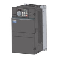
Mitsubishi Electric FR-A720-02150-NA Instruction Manual (105 pages)
FR-A7NF series INVERTER Plug-in option FL remote communication function
Brand:
Mitsubishi Electric
| Category:
Air Conditioner
| Size: 2 MB
Table of Contents
Safety Instructions
2
Table of Contents
4
1 Pre-Operation Instructions
7
Inverter Model
7
Unpacking and Product Confirmation
8
Product Confirmation
8
SERIAL Number Check
9
Parts
13
LED Status
14
Device Status LED (DEV), Remote Status LED (RMT)
15
Transmitting (Tx)/Receiving (RX) LED
16
Communication Set Status LED (CHG)
16
Specifications
17
Inverter Option Specifications
17
Communication Specifications
17
Installation
18
2 INSTALLATION Pre-Installation Instructions
18
Installation of the Communication Option LED Display Cover
19
Installation Procedure
20
Node Address Setting
22
3 Wiring
23
Connection to Network
23
Cable Specifications
24
Precautions for System Configuration
24
Wiring
25
4 Inverter Setting
27
Parameter List
27
Fl Remote Communication
29
Operation Mode Setting
30
Operation Mode Indication
30
Operation Mode Switchover Method
31
Selection of Control Source for the Network Operation Mode
36
Operation at Communication Error Occurrence
38
Operation Selection at Communication Error Occurrence (Pr. 501, Pr. 502)
38
Fault and Measures
40
Inverter Reset
42
Frequency and Speed Conversion Specifications
43
5 Fl Remote Communication Function
44
Functions
44
Output from the Inverter to the Network
44
Input to the Inverter from the Network
45
Types of Data Communication
46
6 Cyclic Transmission
47
Common Memory
48
Common Memory Area 1
50
Common Memory Area 2
51
Output Data (Master to Inverter)
54
Control Input Command
55
Set Frequency
57
Input Data (Inverter to Master)
58
Inverter Status Monitor
59
Fault Code
61
Life/Warning
61
Output Frequency Monitor
63
Output Current Monitor
63
7 Message Transmisson
64
Error Response at Word Block Read/Write
67
Word Block Read/Write
68
Virtual Address Space of Word Block Read/Write
69
Product Information
70
Operation Mode
72
Inverter Status
73
Set Frequency
74
Inverter Monitor
75
Parameter
78
Calibration Parameters
80
Fault Record
82
Network Parameter Read
88
Log Data Read
91
Log Data Clear
94
Profile Read
95
Message Loopback
99
8 Description and Corrective Action of Fault Indication
100
9 Troubleshooting
101
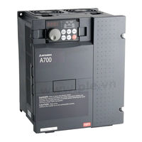
Mitsubishi Electric FR-A720-02150-NA Instruction Manual (86 pages)
Plug-in option SSCNET III communication function 700 Series
Brand:
Mitsubishi Electric
| Category:
Inverter
| Size: 2 MB
Table of Contents
Instruction Manual
1
Safety Instructions
2
Table of Contents
4
1 Pre-Operation Instructions
7
Inverter Type
7
Unpacking and Product Confirmation
8
Packing Confirmation
13
Parts
14
Caution
15
Operation Overview
16
2 Installation
18
Pre-Installation Instructions
18
Shaft Number Setting
19
Installation Procedure
20
3 Wiring
22
System Configuration (When FR-A7AP Is Used)
22
Wiring Example (When FR-A7AP Is Used)
24
SSCNET III Cable
26
SSCNET III Cable Laying
30
Wiring
32
4 Sscnet III Communication Status
38
5 Inverter Setting and Display
41
Parameter List
41
Operation Mode Setting
42
Operation Mode Indication
42
Operation Mode Switchover Method
43
Operation at Communication Error Occurrence
46
Alarm and Measures
46
Inverter Reset
47
Setting SSCNET III Communication Function
48
Pr.499 SSCNET III Operation Selection
48
Pr.379 SSCNET III Rotation Direction Selection
53
Pr.449 SSCNET III Input Filter Setting
54
Pr.52 DU/PU Main Display Data Selection
54
Pr.185 JOG Terminal Function Selection
55
Pr.800 Control Method Selection
55
6 Restrictions on the Functions
56
Function Restriction List
56
Inverter Parameter List
59
Inverter I/O Terminal Function List
75
Input Terminal Function
75
Output Terminal Function
78
Precautions
80
Alarm Indication Definitions
81
Alarm Indication Definitions and Corrective Actions
82
Troubleshooting
85
Advertisement
Advertisement
Related Products
Mitsubishi Electric FR-A720-55K
Mitsubishi Electric FR-A720-75K
Mitsubishi Electric FR-A720-02880-NA
Mitsubishi Electric FR-A740-55K
Mitsubishi Electric FR-A740-75K
Mitsubishi Electric FR-A740-01100-NA
Mitsubishi Electric FR-A740-01440-NA
Mitsubishi Electric FR-A740-01800-EC
Mitsubishi Electric FR-A740-55K-CHT
Mitsubishi Electric FR-A740-75K-CHT
Mitsubishi Electric Categories
Air Conditioner
Controller
Projector
Inverter
Heat Pump
More Mitsubishi Electric Manuals
Login
Sign In
OR
Sign in with Facebook
Sign in with Google
Upload manual
Upload from disk
Upload from URL