Sign In
Upload
Manuals
Brands
Mircom Manuals
Control Panel
FX-2000 series
Mircom FX-2000 series Manuals
Manuals and User Guides for Mircom FX-2000 series. We have
5
Mircom FX-2000 series manuals available for free PDF download: Installation And Operation Manual, User Manual, Installation And Wiring Manual, Operation
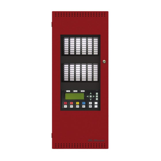
Mircom FX-2000 series Installation And Operation Manual (88 pages)
Brand:
Mircom
| Category:
Control Panel
| Size: 3 MB
Table of Contents
Table of Contents
3
Introduction
7
About the FX-2000
7
Overall Features
7
Document Conventions
8
Circuits and Zones
8
Wiring Styles
8
System Components
9
Chassis Types
9
Adder Modules
9
Auxiliary Models
10
Enclosures
10
Flush Trim Rings
10
Remote Annunciators
11
Batteries
11
FX-2000 Accessories
11
Mechanical Installation and Dimensions
12
Figure 2: BBX-1072A Flush or Surface Enclosure Installation and Dimensions
13
Figure 3: BB-5008 Enclosure Installation Instructions and Dimensions
14
Chassis Installation
15
Figure 5: Chassis Installation into BBX-1072A
16
Figure 6: Installation Instructions and Dimensions for BB-5014
17
Module Mounting Locations
18
Display and Adder Modules Mounting Locations
19
FX-2003-6/FX-2003-12 Compact Main Chassis
19
FX-2017-12 MID-Size Main Chassis
20
FX-2009-12 Large Main Chassis
20
ECX-0012 Expander Chassis for FX-2009-12
20
Module Settings
22
Main Fire Alarm Modules (MD-764 Part of Main Chassis)
22
Main Fire Alarm Super Module (MD-757 Part of "S" Version Main Chassis)
23
Figure 11: Main Display Module (Part of Main Chassis)
24
Figure 13: IPS-2424 Programmable Input Switches Module
25
Figure 15: FDX-008 Block Diagram of Fan and Monitor Setup
26
Figure 16: FDX-008KI Fan Damper Control Display Module
27
Figure 17: Hardwire Detection Adder Module (DM-1008A)
28
Polarity Reversal and City Tie Module (Model PR-300)
30
Udact-300A Main Board
31
Table 2: Cable Connectors and Miscellaneous
32
ALC-198S Single Intelligent Analog Loop Controller Module
33
Figure 22: ALC-198S Single Intelligent Analog Loop Controller Module
34
ALC-396S Dual Intelligent Analog Loop Controller Module
35
Figure 23: ALC-396S Dual Intelligent Analog Loop Controller Module
36
ALC-H16 Hardwire Loop Controller Module
37
Figure 24: ALC-H16 Hardwire Loop Controller Module
38
Field Wiring
39
Main Fire Alarm Module Terminal Connections
39
Figure 26: Main Fire Alarm Module Terminal Connections (Continued)
40
Analog Loop Wiring
41
Figure 28: Loop Terminal Connections - Style 7
42
Figure 29: Loop Terminal Connections - Style 6 (Formerly Class A)
43
Figure 30: Single Loop Terminal Connections - Class B
44
Figure 31:Single Loop Terminal Connections - Style 7
45
Figure 32: Single Loop Terminal Connections - Style 6
46
Detection Module (DM-1008A) Terminal Connections
47
Signal Module (SGM-1004A) Terminal Connections
48
Relay Module (RM-1008(A)) Terminal Connections
49
Polarity Reversal and City Tie Module (PR-300) Wiring
50
UDACT-300A Main Board Terminal Connections
51
Power Supply Connections
52
Wiring Tables and Information
53
Table 7: Analog Loop Wiring
54
System Checkout
55
Before Turning the Power on
55
Power-Up Procedure
55
Troubleshooting
55
Indicators, Controls, and Operation
56
Common Indicators
57
Common Controls
58
Single Stage Operation
60
Two Stage Operation
60
Pre-Signal Operation
61
Circuit Types
62
Appendix A: Specifications
65
Compliance
66
Appendix B: Compatible Devices
67
FX-2000 Series Compatible Addressable Loop Modules (UL)
67
FX-2000 Series Compatible Two-Wire Smoke Detectors (UL Listed)
68
FX-2000 Series Compatible Four-Wire Smoke Detectors (UL Listed)
70
FX-2000 Series Compatible Signalling Devices (UL Listed)
71
FX-2000 Series Compatible Addressable Loop Modules (ULC)
72
FX-2000 Series Compatible Hardwire Smoke Detectors (ULC Listed)
73
FX-2000 Series Compatible Synchronized Modules and Strobes
75
Appendix C: Power Supply and Battery Calculations
76
Appendix D: Remote Annunciator Panels
77
RA-1000 & RAM-200 Series
77
Rax-Lcd
77
Appendix E: DIP Switch Settings Summary
78
Appendix F: Alarm Verification Timing
81
Warranty & Warning Information
83
Warning Please Read Carefully
83
Limited Warranty
85
Warranty Procedure
85
Disclaimer of Warranties
85
Out of Warranty Repairs
86
Advertisement
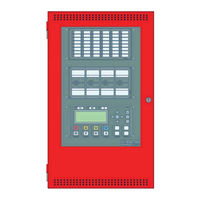
Mircom FX-2000 series Installation And Operation Manual (109 pages)
Intelligent Analog Fire Alarm Control Panel
Brand:
Mircom
| Category:
Control Panel
| Size: 2 MB
Table of Contents
Table of Contents
2
1 Introduction
4
2 Document Conventions
6
3 System Components
7
4 Mechanical and Chassis Installation
15
5 Module Mounting Locations
26
6 Display and Adder Modules Mounting Locations
28
FX-2003-6DS/FX-2003-12DS/FX-2003-6DS-16LED Compact Main Chassis
28
FX-2017(S)-12DS MID-Size Main Chassis
28
FX-2009(S)-12DS Large Main Chassis
29
ECX-0012 Expander Chassis for FX-2009-12DS
29
7 Module Settings
32
Main Fire Alarm Modules (MD-764 Part of Main Chassis)
32
Main Fire Alarm Super Module (MD-757 Part of "S" Version Main Chassis)
33
RAX-1048TZDS Zone Display Module
35
IPS-2424DS Programmable Input Switches Module
35
Fan Damper Control Display Module (FDX-008W/WKI)
36
DM-1008A Hardwire Detection Adder Module
39
SGM-1004A Hardwire NAC Signal Adder Module
40
RM-1008A Hardwire Relay Adder Module
42
Polarity Reversal and City Tie Module (Model PR-300)
43
UDACT-300A Main Board
44
ALC-H16 Hardwire Loop Controller Module
50
8 Field Wiring
52
Main Fire Alarm Module Terminal Connections
52
Analog Loop Wiring
54
NAC Signal Module (SGM-1004A) Terminal Connections
61
UDACT-300A Main Board Terminal Connections
64
Wiring Tables and Information
66
9 System Checkout
68
10 Indicators and Controls
69
11 Operation
75
Single Stage Operation
75
Two Stage Operation
76
Pre-Signal Operation
77
UUKL Feature
77
Output Circuit Delay Operation
77
Circuit Types
78
12 Appendix A: Specifications
82
13 Appendix B: Compatible Devices
88
FX-2000 Series Compatible Addressable Loop Devices (UL)
88
FX-2000 Series Compatible Two-Wire Smoke Detectors (UL)
89
FX-2000 Series Compatible Four-Wire Smoke Detectors (UL Listed)
91
FX-2000 Series Compatible Signalling Devices (UL Listed)
91
FX-2000 Series Compatible Addressable Loop Devices (ULC)
92
FX-2000 Series Compatible Hardwire Smoke Detectors (ULC)
93
FX-2000 Series Compatible Synchronized Modules and Strobes
94
14 Appendix C: Power Supply and Battery Calculations
95
15 Appendix D: Remote Annunciator Panels
97
16 Appendix E: DIP Switch Settings Summary
99
17 Appendix F: Alarm Verification Timing
101
18 Appendix G: Wiring for Supervised Output Module
102
19 Appendix H: Label Requirements for Zone Identification
103
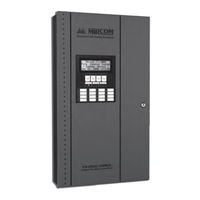
Mircom FX-2000 series User Manual (36 pages)
Fire Alarm Control Panel
Brand:
Mircom
| Category:
Control Panel
| Size: 7 MB
Table of Contents
Table of Contents
3
Introduction
4
About this Manual
4
Technical Support
4
Front Panel Indicators, Controls, and Operation
5
Front Panel Indicators and Control Locations (Classic Display)
5
Front Panel Indicators and Control Locations (New DS Display)
6
Switch Numbering (New DS Display)
7
Common Indicators
7
Common Controls
9
Troubleshooting
12
Start up
13
Menu Mode
14
Passcodes
15
Front Panel Menu Operation
16
1 Reports Menu
16
2 Bypass Menu
21
3 Walk Test Menu
25
Alternate Menu Option #3: Manual Control Enable
28
4 Change Passcode
29
5 Day/Night Mode
30
6 Set Time/Date
31
7 Clear Event Log
32
8 Clear Verification Counter
33
9 Auto Program
34
Advertisement
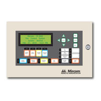
Mircom FX-2000 series Installation And Wiring Manual (24 pages)
Remote Annunciator Panel
Brand:
Mircom
| Category:
Control Panel
| Size: 1 MB
Table of Contents
Table of Contents
3
Introduction
7
Contact Us
8
General Inquiries
8
Customer Service
8
Technical Support
8
Website
8
Installation Instructions
9
Wiring Instructions
10
DIP Switch Settings
12
The RAX-1048 Adder Annunciator Chassis
13
The IPS-2424 Programmable Input Switches Module
13
The RAX-LCD Shared Display Chassis
14
Specifications and Features
15
Enclosure Models
15
Module Models
15
RAX-LCD Remote FX-2000 Shared Display LCD Annunciator
15
RAX-1048TZ Adder Annunciator Chassis (48 Display Points)
15
Current Drain for Battery Calculations
16
Environmental Specifications
16
Warranty and Warning Information
17
Warning Please Read Carefully
17
Note to Installers
17
System Failures
17
Inadequate Installation
17
Power Failure
17
Failure of Replaceable Batteries
17
Compromise of Radio Frequency (Wireless) Devices
18
System Users
18
Automatic Alarm Initiating Devices
18
Software
18
Alarm Notification Appliances
18
Telephone Lines
19
Mircom FX-2000 series Operation (10 pages)
INTELLIGENT FIRE ALARM CONTROL PANEL
Brand:
Mircom
| Category:
Control Panel
| Size: 1 MB
Table of Contents
Operation
2
Electrical Ratings
5
Remote Annunciators
6
Ordering Information
9
Advertisement
Related Products
Mircom FX-2003-6DS
Mircom FX-2017S-12ADS
Mircom FX-2009-12DS
Mircom FX-2009S-12DS
Mircom FX-2003-12XTDS
Mircom FX-2003-6DS-16LED
Mircom FX-2003-12DS
Mircom FX-2017-12ADS
Mircom FX-2200 Series
Mircom FX-400
Mircom Categories
Control Panel
Intercom System
Fire Alarms
Controller
Smoke Alarm
More Mircom Manuals
Login
Sign In
OR
Sign in with Facebook
Sign in with Google
Upload manual
Upload from disk
Upload from URL