Magnum Energy ME3112 Manuals
Manuals and User Guides for Magnum Energy ME3112. We have 2 Magnum Energy ME3112 manuals available for free PDF download: Owner's Manual
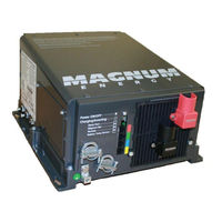
Magnum Energy ME3112 Owner's Manual (62 pages)
Modifi ed Sine Wave Inverter/Chargers
Brand: Magnum Energy
|
Category: Inverter
|
Size: 4 MB
Table of Contents
Advertisement
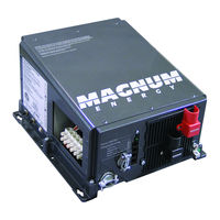
Magnum Energy ME3112 Owner's Manual (62 pages)
ME Series Modifi ed Sine Wave Inverter/Chargers
Brand: Magnum Energy
|
Category: Inverter
|
Size: 3 MB