Sign In
Upload
Manuals
Brands
Kohler Manuals
Controller
Decision-Makerr MPAC 1500
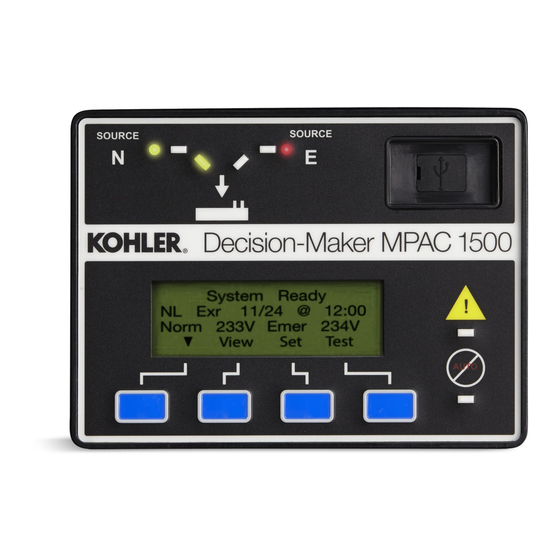
Kohler Decision-Makerr MPAC 1500 Manuals
Manuals and User Guides for Kohler Decision-Makerr MPAC 1500. We have
3
Kohler Decision-Makerr MPAC 1500 manuals available for free PDF download: Manual, Installation Instructions Manual, Installation Instructions
Kohler Decision-Makerr MPAC 1500 Manual (132 pages)
Brand:
Kohler
| Category:
Controller
| Size: 2 MB
Table of Contents
Table of Contents
3
Safety Precautions and Instructions
7
Introduction
9
Service Assistance
10
Section 1 Installation
11
Controller Connections
11
Logic Board Input and Output Connections
12
Communication Connections
12
Controller Connection
12
Controller Ground
12
Extended Transfer Time Relay
13
Accessory Connections
13
Controller Powerup/Reset
13
System Setup
14
Exerciser Setup
14
Functional Tests
14
Warranty Registration
14
Section 2 Operation Tests
15
Introduction
15
Manual Operation Test
15
Voltage Check
15
Lamp Test
15
Automatic Operation Test
15
Section 3 Operation
19
Introduction
19
User Interface Panel
19
Display
19
LED Indicators
20
Pushbuttons
20
Display Contrast
20
Examples
20
Main Screen
23
Passwords
24
Changing Passwords
24
Setup Password Reset and Disable
24
Test Password Reset and Disable
24
Normal Operation Screens
25
Sequence of Operation, Standard Transition
26
Preferred Source Loss and Return
26
Exerciser Operation
26
Test Sequence
27
Sequence of Operation, Programmed-Transition
28
Preferred Source Loss and Return, Programmed-Transition
28
Exerciser Operation, Programmed-Transition
28
Test Sequence, Programmed-Transition
29
Sequence of Operation, Service Entrance Models
30
Preferred Source Loss and Return, Service Entrance Models
30
Exerciser Operation
30
Service Entrance Models
30
Test Sequence
31
Service Entrance Models
31
Test Sequence Service Entrance Models
31
Sequence of Operation, Closed Transition Models
32
Preferred Source Loss and Return, Closed-Transition
32
Failure to Synchronize (Programmed-Transition Override)
32
Exerciser Operation, Closed-Transition
33
Test Sequence, Closed-Transition
33
System Test
35
Unloaded System Test
36
Loaded System Test
36
Closed-Transition Loaded Test
36
Auto-Loaded System Test
37
Sync Check (Closed-Transition)
37
Lamp Test
38
Exercise
38
Unloaded Exercise
38
Load Bank Control
38
Loaded Exercise
38
Warnings and Faults
39
Fault Reset
40
Accessory Module Faults
40
Module Status Change
40
Module Status Conflict
41
Reset Data
42
Reset Maintenance Records
42
Reset Event History
42
Reset Default Parameters
42
Reset and Disable Test Password
44
File Maintenance
44
Section 4 View Screens
45
Introduction
45
Main Screen
45
View Screens
45
View Event History
46
View Maintenance Records
46
View Exerciser Setup
47
View Prime Power Setup
47
View System Setup
47
View Source Setup
48
View Time Delays, Source 1
50
View Time Delays, Source 2
52
View Inputs/Outputs
54
View Common Alarms
54
View Communications Setup
55
View Control Parameters
55
Section 5 Setup
57
Introduction
57
Source Names
57
Controller DIP Switches
57
Default Settings and Time Delays
58
System Parameters
58
Time Delays
58
Setup Screens
59
Time/Date
60
Exerciser
61
Setting the Exerciser
61
Source/Source Mode
61
Prime Power Run
63
Prime Power Mode Setup
63
Prime Power Mode Operation
63
Time Delays
64
Load Control Time Delays
64
Set S1 Time Delays
65
Set S2 Time Delays
67
Load Control
69
Time-Based Load Control
69
Current-Based Load Control
71
Source Setup
73
Phase Rotation
73
In-Phase Monitor
73
Preferred Source Selection
73
System Voltage and Frequency
74
Voltage and Frequency Pickup and Dropout Settings
75
Set Sources
76
Programmable Inputs and Outputs
79
Main Logic Board Inputs and Outputs
79
Input/Output Modules
79
Input Functions
80
Output Functions
81
User-Defined I/O Function Descriptions
82
Common Alarms
83
Common Alarm Output
83
Audible Alarm
83
Chicago Alarm
83
Set System
84
Source Type/Source Type
84
Transition Type
84
Service Entrance
84
Rated Current
84
Three Source Engine Start Mode
84
Transfer Commit
84
Remote Test Loading
85
Peak Shave TD Bypass
85
USB Data Logger
85
Min/Max Values
85
Three-Source Systems
87
Three Source Engine Start Mode
87
Preferred Source Toggle
87
Three Source System Test and Exercise
87
Three-Source System Setup
87
ATS1 and ATS2 System Setup
88
Communications
91
Set Passwords
91
Calibration
92
Section 6 Communications
93
Introduction
93
Connections
93
Serial Connections
94
Ethernet Connections
95
Communications Setup
97
Serial Communication
98
Ethernet Communication
98
USB Port
99
File Transfer
100
Event History Files
101
Configuration Files
101
Controller Application Program
101
Data Logger Files
102
Minmax Files
102
Syncdata Files
102
Section 7 Scheduled Maintenance
103
Introduction
103
Testing
104
Weekly Generator Set Exercise
104
Monthly Automatic Control System Test
104
Inspection and Service
104
General Inspection
104
Other Inspections and Service
105
Service Schedule
106
Section 8 Accessories
107
Introduction
107
Accessory Modules
107
Accessory Module Mounting
107
Input/Output (I/O) Modules
108
Alarm Module
109
Alarm Board DIP Switches
110
External Alarm
110
Audible Alarm Setup
110
Alarm Operation
110
Alarm Silence Mode
110
External Battery Supply Module (EBSM)
111
Heater
112
Transient Voltage Surge Suppressor (TVSS)
113
Diagnostic Leds
113
TVSS Remote Status Indicator
113
TVSS Replacement
114
Supervised Transfer Control Switch
116
Automatic Mode
116
Non-Automatic Mode
116
Current Sensing
118
Load Shed (Forced Transfer to OFF)
120
Description
120
Connection
120
User Interface Cover
121
Line-To-Neutral Voltage Monitoring
121
Logic Disconnect Switch
122
Monitoring Program
122
Appendix A Abbreviations
123
Appendix B Screen Summaries
125
Advertisement
Kohler Decision-Makerr MPAC 1500 Installation Instructions Manual (49 pages)
Brand:
Kohler
| Category:
Controller
| Size: 3 MB
Table of Contents
Installation Instructions
1
Remote Serial Annunciator Diagram
1
The Unit with Single ATS Control
1
The Unit with Four ATS Controls
1
Kit Selection
2
Communication Module for DEC 3+ Controller
3
Features
3
Horn
3
Switches with Operating Information
3
To Start a Loaded Remote Test
4
To Stop a Remote Test
4
Communications
4
Leds
4
System Monitoring Leds and Functions
5
Communication Status
6
Common Fault
6
User Defined Inputs and EPS Supplying Load Defaults
6
Emergency Power System (EPS) Supplying Load
7
High Engine Temperature
7
Low Fuel (Level or Pressure)
7
Low Oil Pressure
7
Mounting
8
Safety Precautions
8
User Programmed Inputs #1 to #5
8
Disabling the Generator Set
8
Accessing the Middle Compartment on the Control Panel
9
Electrostatic Discharge Damage
9
Installation Procedure
10
Remove the Generator Set from Service
10
Remove the Gauge Driver Board in the DEC 3+ Controller
10
Communication Module Schematic, DEC 3+ Controller
11
Mount the Communication Module Board in the DEC 3+ Controller
12
Wire the Communication Module Board in the DEC 3+ Controller
12
Select a Mounting Location for the Unit
13
Communication Module TB5 Terminal Strip Connections
13
Wire Specifications for Communication Module Connections
13
Remote Serial Annunciator Dimension Print
14
Mounting Hole Dimensions in Supplied Box
16
Wire the Unit
17
Drilling Mounting Holes in Hoffman Box for Front Panel Assembly
17
Wire Specifications between the Unit and Generator Set Controller
17
Circuit Board GM86125 Connectors
18
P27 Connector on Master RSA III
19
RS-485 Connector Details
19
P27 Connection on RSA III Slave
19
Controller Base Module View
20
Connectors on TB10
20
DEC 3+ Controller RS-485 Connections
20
DEC 3+ Controller P21 RS-485 Connections
20
DEC 3000 Controller RS-485 Connectors
21
DEC 3000 P21 RS-485 Connections
21
DEC 3500 Controller RS-485 Connectors
21
DEC 3500 TB12 RS-485 Connections
21
DEC 550 and DEC 6000 Controllers P20 RS-485 Connections
22
DEC 550 Controller RS-485 Connections
22
DEC 6000 Controller RS-485 Connections
22
DEC 8000 Base Box and RS-485 Connectors
23
AC Adapter Kit View
24
P37 Power/Can Connections
24
P39 Isolation Jumper Connections
25
P40 Common Fault Output and Alarm Horn Dry Contacts
25
RSA P41User Input 1--3 Connections
26
RSA P42 User Input 4--5 Connections
26
RSA III Local P42 Input Connections
26
Local P41 Input Connections
26
Digital Inputs on APM802 Controller
27
Unit's Remote User Inputs with DEC 550 and DEC 6000 Controllers
27
Binary Inputs on DEC 8000 Controller
27
Complete the RSA III Final Installation
28
Surface Mount RSA III Final Installation
28
Flush Mount RSA III Final Installation
28
EPS Supplying Load (ATS) Annunciation Sources
28
Configure the DEC 3+ Controller for the Remote Serial Annunciator
29
Restore the Generator Set to Service
29
Configure the APM802 Controllers for the Remote Serial Annunciator
29
APM802 Configuration
29
Sitetecht Software Settings
30
Configure DEC 550/DEC 6000 Controllers for Remote Serial Annunciator
30
Configure DEC 3000/DEC 3500 Controllers for Remote Serial Annunciator
30
Generator Set and ATS Setup on Sitetecht (Sample Screen)
31
Menu List Summary
32
User-Defined Settings Table
33
Identity Field
34
Modbusr Baud Rate
34
Product Connections
34
Product Connection Inputs
34
Wiring Diagram
36
Interconnection Diagram
43
Parts List
45
Kohler Decision-Makerr MPAC 1500 Installation Instructions (2 pages)
Brand:
Kohler
| Category:
Controller
| Size: 0 MB
Table of Contents
Introduction
1
Safety Precautions
2
Instructions
2
Normal Source Failure and Return
2
Monitor III Software
2
Input/Output Modules
2
USB Port
2
Fuse
2
Parts List
2
Advertisement
Advertisement
Related Products
Kohler Decision-Makerr MPAC 750
Kohler Decision-Makerr MPAC 1000
Kohler Decision-Makerr MPAC 1200
Kohler Modbus MPAC 1000
Kohler Mira Showers Platinum Dual
Kohler Decision-Makerr 3+
Kohler Decision-Makerr 550
Kohler Decision-Makerr 6000
Kohler Decision-Makerr 8000
Kohler Decision-Makerr 3000
Kohler Categories
Plumbing Product
Bathroom Fixtures
Toilets
Bathtubs
Engine
More Kohler Manuals
Login
Sign In
OR
Sign in with Facebook
Sign in with Google
Upload manual
Upload from disk
Upload from URL