Sign In
Upload
Manuals
Brands
Kamstrup Manuals
Temperature Controller
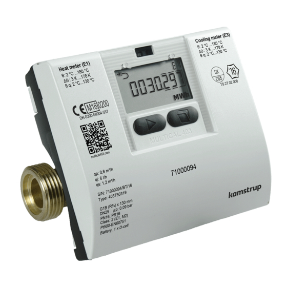
MULTICAL 403
Kamstrup MULTICAL 403 Manuals
Manuals and User Guides for Kamstrup MULTICAL 403. We have
5
Kamstrup MULTICAL 403 manuals available for free PDF download: Technical Description, Installation And User Manual, Installation & Maintenance Instructions Manual
Kamstrup MULTICAL 403 Technical Description (145 pages)
Brand:
Kamstrup
| Category:
Measuring Instruments
| Size: 8 MB
Table of Contents
Table of Contents
3
1 General Description
8
Mechanical Construction
9
Electronic Structure
10
2 Technical Data
11
Approved Meter Data
11
Electrical Data
13
Mechanical Data
15
Materials
15
Accuracy
16
3 Type Overview
17
Type Number
18
Accessories
19
Configuration Numbers
22
Flow Sensor Position >A
23
Measuring Unit >B
23
Flow Sensor Coding >CCC
23
Display Code >DDD
25
Tariffs >EE
28
Pulse Inputs a and B >FF-GG
33
Integration Mode >L
36
Cold Water Leakage >N
37
Pulse Outputs C and D >PP
37
Data Logger Profile >RR
39
Encryption Level >T
41
Customer Label >VVVV
41
Data
42
Serial Number and Extended Availability
44
Target Date
45
4 Installation
46
Installation Requirements
46
Inlet Prerequisites
47
Orientation of Kamstrup's Flow Sensors
48
General Recommendations
48
Recommendations for Heat Applications
49
Recommendations for Cooling and Combined Heat/Cooling Applications
50
Recommendations for Directly Mounted Temperature Sensors
51
Mounting of MULTICAL® 403 Calculator
52
Compact Mounting
52
Wall Mounting
52
Position of Calculator
52
Operating Pressure of MULTICAL® 403
53
Mounting in Inlet or Outlet
54
EMC Conditions
54
Climatic Conditions
54
Sealing
55
Pressure Loss
55
5 Dimensioned Sketches
57
6 Display
60
USER Loop
64
TECH Loop
64
Module Readings
68
SETUP Loop
70
Change of Parameters in the "SETUP Loop
71
TEST Loop
79
7 Calculator Functions
80
Application Types and Energy Calculations
80
Heat/Cooling Energy Registers E1 and E3
80
Energy Registers E8 and E9
81
Outlet Energy Registers A1 and A2
82
Energy Calculations
83
Measurement of the Coefficient of Performance (CP) of a Heat Pump
85
Measurement of the Coefficient of Performance (CP) of a Gas Boiler
87
Offset Adjustment of Temperature Sensor Measurement
87
Bifunctional Heat/Cooling Metering
88
Min/Max Calculations of Power (P) and Flow (Q)
89
Temperature Measurement
91
Information Code Types
92
Examples of Information Codes
93
Information Codes in Display and in Serial Communication
94
Information Codes in Transport State
95
Transport State
95
Info and Config Logger
97
Info Logger
97
Config Logger
97
Summer/Winter Time Adjustment
98
8 Flow Sensor
99
Measuring Principles
99
Signal Path and Flow Calculation
99
Flow Limits
101
9 Temperature Sensors
102
Temperature Sensor Types
103
Cable Effect
104
Installation
104
Identification of Inlet and Outlet Temperature Sensors
104
Electrical Connection
105
Pt500 Direct Short Sensor Set
105
Pt500 Ø5,0 MM / Ø5,2 MM Sensor Types
107
Pt500 Ø5.8 MM / Ø6.0 MM Pocket Sensor Set
109
10 Power Supply
110
Battery, 2 X A-Cells
110
Lithium Battery, 1 X D-Cell
111
Lithium Battery, 1 X C-Cell Iot
111
Battery Lifetimes
112
VAC Supply Module
113
VAC High-Power SMPS
114
VAC/VDC High-Power SMPS
114
Power Consumption of Mains Connected Meter
114
Safety Transformer 230/24 VAC
115
Supply Cables for Supply Module
115
Retrofitting and Exchange of Supply Modules
116
Data-Backup in Case of Interruption of Supply
117
11 Communication Modules
118
Marking on Communication Modules
119
Modules
120
HC-003-10: Data Pulse, Inputs (In-A, In-B)
120
HC-003-11: Data Pulse, Outputs (Out-C, Out-D)
120
HC-003-20: Wired M-Bus, Inputs (In-A, In-B)
120
HC-003-21: Wired M-Bus, Outputs (Out-C, Out-D)
121
HC-003-22: Wired M-Bus, Thermal Disconnect
121
HC-003-30: Wireless M-Bus, Inputs (In-A, In-B)
121
HC-003-31: Wireless M-Bus, Outputs (Out-C, Out-D)
122
HC-003-32: Linkiq/Wm-Bus, Inputs (In-A, In-B), EU
122
HC-003-33: Linkiq/Wm-Bus, Outputs (Out-C, Out-D),EU
122
HC-003-34: Wm-Bus, Inputs (In-A, In-B),912,5/915/918,5 Mhz
123
HC-003-40: Analog Outputs 2 X 0/4
123
HC-003-42: KNX Comminication
123
HC-003-43: PQT Controller
123
HC-003-50: Low Power Radio, Inputs (In-A, In-B), 434 Mhz
124
HC-003-51: Low Power Radio GDPR, Inputs (In-A, In-B), 434 Mhz
124
HC-003-53: Lorawan (Elvaco)
124
HC-003-56: NB-Iot, Inputs (In-A, In-B)
125
HC-003-58: NB-Iot (Elvaco)
125
HC-003-66: Bacnet MS/TP, Inputs (In-A, In-B)
125
HC-003-67: Modbus RTU, Inputs (In-A, In-B)
126
HC-003-81: Bacnet IP, Inputs (In-A, In-B)
126
HC-003-82: Modbus/Kmp TCP/IP, Inputs (In-A, In-B)
126
HC-003-83: Ready Ethernet, Inputs (In-A, In-B)
126
Reading High Resolution Registers
127
Mounting of Antenna
127
Module Retrofitting
128
Supply of Modules
129
12 Data Communication
130
Multical
130
Optical Interface
130
Power-Saving in Connection with the Optical Interface
130
Data Protocol
130
13 Test and Calibration
131
Meter Cycle
131
Test
132
Test of Flow Sensor
132
Test of Calculator
132
High-Resolution Volume and Energy
133
Temperature Calibration
133
Pulse Interface
133
Verification Pulses
134
Use of High-Resolution Pulses
134
True Energy Calculation
135
14 Calibration of MULTICAL® 403 Using METERTOOL HCW
136
Calibration Equipment
136
Functional Description
137
Calibration Data
137
Start of Calibration
138
Printing of Certificate
138
Logview HCW
139
Application
140
15 Approvals
141
Type Approvals
141
The Measuring Instruments Directive
141
16 Troubleshooting
142
17 Disposal
143
18 Documents
144
Advertisement
Kamstrup MULTICAL 403 Technical Description (136 pages)
Brand:
Kamstrup
| Category:
Measuring Instruments
| Size: 5 MB
Table of Contents
Table of Contents
3
1 General Description
8
Mechanical Construction
9
Electronic Structure
10
2 Technical Data
11
Approved Meter Data
11
Electrical Data
13
Mechanical Data
15
Materials
15
Accuracy
16
3 Type Overview
17
Type Number
18
Accessories
19
Configuration Numbers
21
Flow Sensor Position >A
22
Measuring Unit >B
22
Flow Sensor Coding >CCC
22
Display Code >DDD
23
Tariffs >EE
26
Pulse Inputs a and B >FF-GG
32
Integration Mode >L
35
Cold Water Leakage >N
36
Pulse Outputs C and D >PP
36
Data Logger Profile >RR
37
Encryption Level >T
39
Customer Label >VVVV
40
Data
40
Serial Number and Extended Availability
42
4 Installation
43
Installation Requirements
43
Mounting of MULTICAL® 403 Flow Sensor
44
Mounting of Couplings and Short Direct Sensor in MULTICAL® 403 Flow Sensor
44
Flow Sensor Position
44
Installation Angle of Flow Sensor
45
Mounting of MULTICAL® 403 Calculator
46
Compact Mounting
46
Wall Mounting
46
Position of Calculator
46
Mounting in Inlet or Outlet
48
EMC Conditions
48
Climatic Conditions
48
Sealing
49
Pressure Loss
49
5 Dimensioned Sketches
51
6 Display
54
USER Loop
57
TECH Loop
57
SETUP Loop
63
Change of Parameters in SETUP Loop
64
Table of Contents
65
Date
66
Monthly Target Date 1 (DD)
66
Time
66
Bus Primary Address
67
Flow Sensor Position: Inlet or Outlet (A-Code)
67
Measuring Unit and Resolution (B and CCC Code)
67
Averaging Period of Min/Max P and Q
68
Heat/Cooling Shift
68
R0 )
69
Temperature Sensor Offset
69
Radio On/Off
70
Endsetup
71
TEST Loop
72
7 Calculator Functions
73
Application Types and Energy Calculations
73
Heat/Cooling Energy Registers E1 and E3
73
Energy Registers E8 and E9
74
Outlet Energy Registers A1 and A2
75
Energy Calculations
76
Measurement of the Coefficient of Performance (CP) of a Heat Pump
78
Measurement of the Coefficient of Performance (CP) of a Gas Boiler
80
Offset Adjustment of Temperature Sensor Measurement
80
Combined Heat/Cooling Metering
81
Min/Max Calculations of Power (P) and Flow
82
Temperature Measurement
84
Information Code Types
85
Examples of Information Codes
86
Information Codes in Display and in Serial Communication
87
Information Codes I Transport State
87
Transport State
87
Info and Config Logger
89
Info Logger
89
Config Logger
89
Summer/Winter Time Adjustment
90
8 Flow Sensor
91
Measuring Principles
91
Signal Path and Flow Calculation
91
Flow Limits
93
9 Temperature Sensors
94
Sensor Types
95
Cable Influence
96
Installation
96
Electrical Connection
96
Pt500 Short Direct Sensor Pair
96
Pt500 Pocket Sensor Pair
98
10 Power Supply
99
Battery, 2 X A-Cells
99
Lithium Battery, 1 X D-Cell
100
Battery Lifetimes
101
230 VAC Supply Module
102
Power Consumption of Mains Connected Meter
102
Transformer 230/24 VAC
103
Supply Cables for Supply Module
103
Replacement of Supply Module
104
Data-Backup in Case of Interruption of Supply
104
Danish Regulations for Mains Connection of Meters
104
11 Communication Modules
105
Marking of Communication Modules
105
Modules
106
Data + Pulse Inputs (Type no
106
Data + Pulse Outputs (Type no
107
M-Bus + Pulse Inputs (Type no
107
M-Bus + Pulse Outputs (Type no
108
M-Bus + Thermal Disconnect (Type no
108
Wireless M-Bus + Pulse Inputs (Type no
109
Wireless M-Bus + Pulse Outputs (Type no
109
Analog Outputs (Type no
110
Bacnet MS/TP + 2 Pulse Inputs (Type no
110
Modbus RTU + 2 Pulse Inputs (Type No.: HC-003-67)
111
Mounting of Antenna
111
Retrofitting Modules
112
Supply of Modules
113
12 Data Communication
114
MULTICAL 403 Data Protocol
114
Optical Eye
114
Power-Saving in Connection with the Optical Eye
114
Data Protocol
114
13 Test and Calibration
115
Meter Cycle
115
Connector
116
Test
116
Test of Flow Sensor
116
Test of Calculator
116
High-Resolution Volume and Energy
117
Temperature Calibration
117
Pulse Interface
117
Verification Pulses
118
Use of High-Resolution Pulses
118
True Energy Calculation
119
14 Metertool Hcw
120
Introduction
120
System Requirements
120
Interface
120
Installation of METERTOOL HCW
121
Settings in METERTOOL HCW
122
How to Use METERTOOL HCW
123
Meter Details
124
Configuration
125
Time / Date
125
Modules
125
Pre-Setting Pulse Inputs a and B
126
Data Logger Reset
126
Autointegration
126
15 Calibration of MULTICAL® 403 Using METERTOOL HCW
127
Calibration Equipment
127
Functional Description
128
Calibration Data
128
Start of Calibration
129
Printing of Certificate
129
Logview HCW
130
Application
131
16 Approvals
132
Type Approvals
132
The Measuring Instruments Directive
132
17 Troubleshooting
133
18 Disposal
134
19 Documents
135
Kamstrup MULTICAL 403 Installation And User Manual (24 pages)
Brand:
Kamstrup
| Category:
Industrial Equipment
| Size: 2 MB
Table of Contents
Table of Contents
3
General Information
4
Mounting of Temperature Sensors
5
Short Direct Sensor (DS)
5
Pocket Sensor (PL)
6
Temperature Sensor Compatibility with Flow Sensors
6
Mounting of Flow Sensor
7
Mounting of Couplings and Short Direct Sensor in Flow Sensor
7
Flow Sensor Position
8
Installation of MULTICAL® 403 Flow Sensor
8
Installation Examples
10
Humidity and Condensation
10
Mounting the Calculator
11
Compact Mounting
11
Wall Mounting
11
Position of Calculator
12
Information Codes "INFO
13
Power Supply
14
Battery Supply
14
Mains Supply
14
Testing of Function
15
Electrical Connection
15
Communication Modules
16
Module Overview
16
Pulse Inputs
16
Pulse Outputs
17
Data Pulse, Inputs (In-A, In-B), Type HC-003-10
17
Data Pulse, Outputs (Out-C, Out-D) , Type HC-003-11
17
Wired M-Bus, Inputs (In-A, In-B), Type HC-003-20
18
Wired M-Bus, Outputs (Out-C, Out-D), Type HC-003-21
18
Wireless M-Bus, Inputs (In-A, In-B), 868 Mhz, Type HC-003-30
18
Wireless M-Bus, Outputs (Out-C, Out-D), 868 Mhz, Type HC-003-31
18
Analog Outputs 2 X 0/4
19
PQT Controller, Type HC-003-43
19
Low Power Radio, Inputs (In-A, In-B), 434 Mhz, Type HC-003-50
19
Low Power Radio GDPR, Inputs (In-A, In-B), 434 Mhz, Type HC-003-51
19
LON TP/FT-10, Inputs (In-A, In-B), Type HC-003-66
20
Modbus RTU, Inputs (In-A, In-B), Type HC-003-67
20
Set-Up Via Front Keys
21
Advertisement
Kamstrup MULTICAL 403 Installation And User Manual (24 pages)
Brand:
Kamstrup
| Category:
Temperature Controller
| Size: 2 MB
Table of Contents
Table of Contents
3
1 General Information
4
2 Mounting of Temperature Sensors
5
Direct Sensors
5
Pocket Sensors
6
Temperature Sensor Compatibility with Flow Sensors
7
3 Mounting of Flow Sensor
8
Mounting of Couplings, and Short Direct Sensor in MULTICAL® 403 Flow Sensor
8
Flow Sensor Position
9
Mounting of MULTICAL® 403 Flow Sensor
10
Installation Examples
11
Humidity and Condensation
11
4 Mounting the Calculator
12
Compact Mounting
12
Wall Mounting
12
Position of Calculator
13
14 Information Codes "INFO
14
5 Information Codes ”INFO”
15
6 Power Supply
15
Battery Supply
15
Mains Supply
16
7 Function Check
17
8 Electrical Connection
17
9 Communication Modules
18
Module Overview
18
Pulse Inputs
18
Pulse Outputs
18
Data + Pulse Inputs, Type HC-003-10
19
Data + Pulse Outputs, Type HC-003-11
19
M-Bus + Pulse Inputs, Type HC-003-20
19
M-Bus + Pulse Outputs, Type HC-003-21
20
Wireless M-Bus + Pulse Inputs, Type HC-003-30
20
10 Set-Up Via Front Keys
21
Kamstrup MULTICAL 403 Installation & Maintenance Instructions Manual (23 pages)
Brand:
Kamstrup
| Category:
Measuring Instruments
| Size: 1 MB
Table of Contents
Table of Contents
4
1 General Information
5
2 Mounting of Temperature Sensors
6
Direct Sensors
6
Pocket Sensors
7
Temperature Sensor Compatibility with Flow Sensors
8
3 Mounting of Flow Sensor
9
Mounting of Couplings, and Short Direct Sensor in MULTICAL® 403 Flow Sensor
9
Flow Sensor Position
10
Mounting of MULTICAL® 403 Flow Sensor
11
Installation Examples
12
Humidity and Condensation
12
4 Mounting the Calculator
13
Compact Mounting
13
Wall Mounting
13
Position of Calculator
14
14 Information Codes "INFO
15
5 Information Codes ”INFO”
16
6 Power Supply
16
Battery Supply
16
Mains Supply
17
7 Function Check
18
8 Electrical Connection
18
9 Communication Modules
19
Module Overview
19
Pulse Inputs
19
Pulse Outputs
19
Data + Pulse Inputs, Type HC-003-10
20
Data + Pulse Outputs, Type HC-003-11
20
M-Bus + Pulse Inputs, Type HC-003-20
20
M-Bus + Pulse Outputs, Type HC-003-21
21
Wireless M-Bus + Pulse Inputs, Type HC-003-30
21
10 Set-Up Via Front Keys
22
Advertisement
Related Products
Kamstrup MULTICAL 402
Kamstrup MULTICAL 41
Kamstrup MULTICAL 401
Kamstrup flowIQ 4200
Kamstrup MULTICAL 801
Kamstrup MULTICAL 6M2
Kamstrup MULTICAL 602
Kamstrup MULTICAL 603
Kamstrup MULTICAL 62
Kamstrup MULTICAL 61
Kamstrup Categories
Measuring Instruments
Industrial Equipment
Media Converter
Control Unit
Modem
More Kamstrup Manuals
Login
Sign In
OR
Sign in with Facebook
Sign in with Google
Upload manual
Upload from disk
Upload from URL