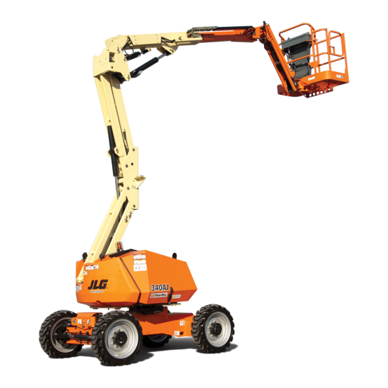
Sign In
Upload
Manuals
Brands
JLG Manuals
Lifting Systems
340AJ
JLG 340AJ Manuals
Manuals and User Guides for JLG 340AJ. We have
2
JLG 340AJ manuals available for free PDF download: Service And Maintenance Manual, Operation And Safety Manual
JLG 340AJ Service And Maintenance Manual (371 pages)
Brand:
JLG
| Category:
Boom Lifts
| Size: 34 MB
Table of Contents
Hydraulic System Safety
3
Safe Maintenance
3
General
3
Table of Contents
5
Section 1 - Specifications
19
Operating Specifications
19
Dimensional Data
19
Capacities
19
Tires
19
Engine Data
19
Major Component Weights
20
Hydraulic Oil
20
Function Speeds
21
Test Notes
21
Operator Maintenance and Lubrication Diagram
22
Operator Maintenance
23
Torque Chart
26
Machine Preparation, Inspection, and Maintenance
31
General
31
Pre-Start Inspection
31
Pre-Delivery Inspection and Frequent Inspection
31
Annual Machine Inspection
31
Preventive Maintenance
31
Service and Guidelines
32
General
32
Safety and Workmanship
32
Cleanliness
32
Components Removal and Installation
32
Bearings
33
Gaskets
33
Bolt Usage and Torque Application
33
Hydraulic Lines and Electrical Wiring
33
Component Disassembly and Reassembly
33
Pressure-Fit Parts
33
Hydraulic System
33
Lubrication and Information
34
Changing Hydraulic Oil
34
Battery
34
Lubrication and Servicing
34
Hydraulic System
34
Lubrication Specifications
34
Cylinder Drift
35
Cylinder Leakage Test
35
Theory
35
Cylinder Thermal Drift
35
Pins and Composite Bearing Repair Guidelines
36
Welding on JLG Equipment
36
Do the Following When Welding on JLG Equipment
36
Do NOT Do the Following When Welding on JLG Equipment
36
Inspection and Preventive Maintenance Schedule
37
Hydraulic Oil Operation Chart
40
Engine Oil Operation Chart
41
Chassis and Turntable
43
Tire Replacement
43
Wheel Installation
43
Drive Orientation System
44
Beyond Transport Position - Drive Speed Cutback System
44
Drive/Steer - Boom Function Interlock System (CE ONLY)
44
Drive System
44
Drive Motor Disassembly and Assembly
45
Drive Motor Special Tools
46
Drive Motor Diagram
47
Right Front Drive Hydraulic Lines Diagram
48
Left Front Drive Hydraulic Lines Diagram
49
Right Rear Drive Hydraulic Lines Diagram
50
Left Rear Drive Hydraulic Lines Diagram
51
Drive Hub
52
Roll, Leak and Brake Testing
52
Tightening and Torquing Bolts
52
Measuring Rolling Torque
53
Main Disassembly
53
Housing-Spindle Disassembly
55
Spindle-Brake Subassembly Disassembly
57
Cover Disassembly
58
Planet Gear Subassembly
60
Spindle-Brake Subassembly
61
Housing-Spindle Subassembly
63
Housing-Ring Gear Subassembly
64
Cover Subassembly
65
Main Assembly
66
Integral Brake Check Procedure
67
Drive Hub Assembly
68
Bearing Pressing Tool
69
Drift Pin for Lining up Thrustwashers with Output Planet Gear
70
Bearing Nut Wrench
71
Oscillating Axle System
72
Oscillating Axle Bleeding Procedure
72
Oscillating Axle
73
Chassis Tilt Indicator System
74
Swing Motor
74
Preparation before Disassembly
76
Swing Motor Removal and Installation
76
Swing Motor Disassembly and Inspection
77
Swing Motor Assembly
84
One Piece Stator Construction
90
Two Piece Stator Construction
91
Final Checks
92
Installation
92
Swing Drive Removal
92
Swing Drive Installation
97
Swing Bearing Torque Value
98
Turntable Bearing Mounting Bolt Condition Check
98
Wear Tolerance
98
Swing Bearing Disassembly
100
Swing Gear Assembly
101
Assembly
102
Cable Installation and Identification
103
Engine Operating States
111
Engine Start Conditions
112
Engine RPM Levels
112
Idle RPM
112
MID Engine RPM
112
Engine Stop RPM
112
Engine Controls
113
Multi-Function RPM
113
High Engine RPM
113
Ambient Air Temperature Sensor/Fuel Level Sensor
113
Generator RPM
113
Engine Startup Procedure (Kubota)
114
Kubota Engine
115
Engine Oil Pressure Switch
115
Engine Speed Sensor
115
Coolant Sensor
116
Glow Plugs
116
Engine Speed Actuators
117
Engine Throttle Actuator
117
Proportional Fuel Rack Actuator
118
Alternator Excitation
118
Fuel Pump
118
Shutdown
118
Engine Start
118
Kubota Engine Diagrams
119
GM Dual Fuel Engine
123
Communications with the JLG Control System
123
Engine Start
123
Oil Pressure
123
Engine Speed
123
Coolant Temperature
123
Fuel Select
123
DTC to SPN/FMI Cross Reference Chart
130
Fuel Reserve / Cut-Out System
132
Cold Start System (Diesel Engine)
132
Generator
132
Counterweight
133
Section 4 - Boom & Platform
135
Boom and Platform
135
Transport Position Sensing System
135
Boom Maintenance
135
Disassembly of the Main Boom
135
Platform Control Enable System
135
Assembly of the Main Boom
137
Boom Inspection
137
Main Boom Assembly Diagram
139
Jib/ Platform Support Diagram
140
Boom Cleanliness Guidelines
141
Boom Hydraulic Lines Diagram
142
Rotary Actuator
144
Theory of Operation
144
Making a Seal Tool
145
Tools Required
145
Rotary Actuator Disassembly
146
Rotary Actuator - Exploded View
148
Rotary Actuator Inspection
151
Rotary Actuator Assembly
152
Greasing Thrust Washers
156
Installing Counterbalance Valve
156
Testing the Actuator
156
Rotator Counterbalance Valve
157
Rotary Actuator Installation and Bleeding
158
Boom and Platform Troubleshooting
159
Platform Support Torque Values
160
Lubricating O-Rings in the Hydraulic System
161
Cup and Brush
161
Dip Method
162
Spray Method
162
Brush-On Method
162
Hydraulic Cylinders
163
Cylinders Disassembly and Assembly
163
Disassembly and Assembly Instructions
163
General Information
163
Inspection after Assembly
163
Standard of Maintenance
163
Acceptable Oil Leakage on Cylinder Rod
164
Disassembly Procedure
166
Assembly
169
Tower Lift Cylinder
172
Upper Lift Cylinder
173
Master Cylinder
174
Level Cylinder
175
Jib Cylinder
176
Steer Cylinder
177
Telescope Cylinder
178
Axle Lockout Cylinder
179
Hydraulic Tank
180
Valve Installation
181
Main Pump/Charge Filter Hydraulic Lines Diagram
183
Main Pump/Main Valve Hydraulic Lines Diagram
184
Drive Pump to Main Valve/Tank Hydraulic Lines
185
Main Control Valve Torque Specifications
186
Main Control Valve Identification
187
Flow Divider Valve Torque Specifications
188
Flow Divider Valve Identification
189
Fly Boom Control Valve Identification
192
Upright Control Valve Identification
193
Drive Pump
194
Description
194
Case Drain and Heat Exchanger
195
High Pressure Relief Valve (HPRV) and Charge Check
195
The System Circuit
195
Charge Pressure Relief Valve
196
Drive Pump Hydraulic Schematic
196
Electrical Displacement Control (EDC)
197
Symbol Chart (Drive Pump)
198
Drive Pump Disassembly
199
EDC Control Disassembly
200
Pressure Limiter Removal
201
Charge Pressure Relief Valve Removal
201
High Pressure Relief Valve Removal
201
Endcap Removal
202
Cylinder Block Kit Removal
202
Servo Sleeve Removal
202
Servo Piston Removal
203
Swashplate and Swashplate Bearing Removal
203
Servo Piston Disassembly
203
Drive Pump Inspection
204
Block Spring Removal
204
Drive Pump Assembly
208
Shaft and Seatl Installation
208
Swashplate Bearings and Swashplate Installation
208
Servo Piston Reassembly
209
Servo Piston Installation
209
Servo Cylinder Installation
209
Cylinder Kit Reassembly
210
Cylinder Kit Installation
210
Timing Pin and Endcap Bushing Installation
211
Valve Plate and Endcap Installation
211
Charge Pump Installation
212
End Cover Installation
213
Charge Pressure Relief Valve Installation
213
HPRV Valve Installation
213
Optional Displacement Limiter Installation
214
EDC Control Assembly
214
EDC Control Installation
215
Port Locations and Gauge Installation
216
Fastener Size and Torque Chart
217
Plug Size and Torque Chart
217
Fasteners and Plugs (Hydraulics)
218
Drive Pump Initial Start
220
Initial Startup Procedures
220
Drive Pump Troubleshooting
221
Pump Adjustment
224
Charge Pressure Relief Valve Adjustment
224
Pressure Limiter Adjustment
225
Displacement Limiter Adjustment
227
Control Neutral Adjustment
228
Mechanical Neutral Adjustment
229
Servo Adjustment Side M4
229
Verify Neutral Setting
229
Removing the Pump
230
Electric Control Module
230
Control Solenoids
231
Control Module Removal/Installation
231
Shaft Seal, Roller Bearing and Shaft Replacement
231
Shaft Assembly Diagram
232
Charge Check / HPRV
233
Charge Pressure Relief Valve
233
Gear Pump Disassembly
234
Pressure Limiter Valve Replacement
234
Gear Pump Cutaway
236
Gear Pump Assembly
238
Gear Pump Troubleshooting
244
Low or no Flow from Gear Pump
244
Excessive Noise from Gear Pump
244
External Leakage of the Gear Pump
244
Pressure Setting Procedure
245
Oil Sampling
245
Oil Sampling Port
246
Section 6 - Jlg Control System
247
JLG Control System Analyzer Kit Instructions
247
Introduction
247
Analyzer Menu Structure
248
Using the Hand Held Analyzer
249
To Connect the JLG Control System Analyzer
249
Changing the Access Level of the Hand Held Analyzer
250
Adjusting Parameters Using the Hand Held Analyzer
251
Machine Setup
252
Level Vehicle Description
252
Analyzer Abbreviations
253
Control Module Location
255
Ground Module
256
Platform Module
260
Operator Controls and Switches
262
Ground Control Switches
262
Toggle Switches
262
Control System Startup Checks
263
Analyzer Top Level Menu
266
Analyzer Diagnostic Menu
267
Analyzer Personalities Menu
271
Analyzer Machine Setup Menu
273
Analyzer Calibration Menu
274
Machine Model Adjustment
275
Machine Configuration Programing Information
278
Machine Configuration Programming Settings
282
LSS System
283
Diagnostic Menu
284
Calibration Procedure
285
Accessory Weights
286
Pipe Rack Capacity Reductions
288
Skyglazier Capacity Reductions
288
JLG Control System Testing and Evaluation
290
Testing & Evaluation
290
LSS Troubleshooting Chart
291
Resetting the MSSO System
292
JLG Control System Fault Messages
294
Fault Code Troubleshooting Information
301
Overload Variations
335
Section 7 - Basic Electrical Information & Schematics
337
Basic Electrical Information and Schematics
337
Multimeter Basics
337
Voltage Measurement
337
Backprobing
337
General
337
Grounding
337
Min/Max
337
Polarity
337
Scale
337
Resistance Measurement
338
Continuity Measurement
338
Current Measurement
339
Applying Silicone Dielectric Compound to Electrical Connections
339
Installation of Dielectric Grease
340
Deutsch HD, DT, DTM, DRC Series
340
AMP Seal
340
AMP Mate-N-Lok
341
DIN Connectors
341
Exclusions
341
Brad Harrison/Phoenix Contact M12
342
Amp Junior Timer
342
Sealed Enclosures
342
AMP Connector
343
Assembly
343
Spec Connectors
343
Connector Assembly Diagrams
344
Connector Disassembly
345
Service - Voltage Reading
345
Wedge Lock
345
Connector Installation
346
Deutsch Connectors
347
DT/DTP Series Assembly
347
DT/DTP Series Disassembly
347
HD30/HDP20 Series Assembly
348
HD30/HDP20 Series Disassembly
348
Electrical Schematic
350
Hydraulic Schematic
366
Advertisement
JLG 340AJ Operation And Safety Manual (118 pages)
Boom Lift
Brand:
JLG
| Category:
Lifting Systems
| Size: 6 MB
Table of Contents
Table of Contents
7
Section 1 - Safety Precautions
15
General
15
Pre-Operation
15
Operator Training and Knowledge
15
Workplace Inspection
16
Machine Inspection
17
Operation
17
General
17
Trip and Fall Hazards
18
Electrocution Hazards
19
Tipping Hazards
21
Crushing and Collision Hazards
24
Towing, Lifting, and Hauling
25
Maintenance
25
Maintenance Hazards
25
Battery Hazards
27
Section 2. User Responsibilities, Machine Preparation, and Inspection
29
2.1 Personnel Training
29
Operator Training
29
Training Supervision
29
Operator Responsibility
29
2.2 Preparation, Inspection, and Maintenance
30
Pre-Start Inspection
32
Function Check
33
Skyguard Function Test
34
General
37
Oscillating Axle Lockout Test (if Equipped)
39
Section 3 - Machine Controls and Indicators
41
General
41
Controls and Indicators
41
Ground Control Station
42
Ground Control Indicator Panel
47
Platform Station
49
Platform Control Indicator Panel
53
Section 4 - Machine Operation
57
Description
57
Boom Operating Characteristics and Limitations
58
Capacities
58
Stability
58
Engine Operation
58
Starting Procedure
58
Shutdown Procedure
59
Fuel Reserve / Shut-Off System
59
Engines Only)
59
Traveling (Driving)
62
Traveling Forward and Reverse
64
Steering
64
Platform
64
Platform Level Adjustment
64
Platform Rotation
64
Boom
65
Swinging the Boom
65
Raising and Lowering the Tower Boom
66
Raising and Lowering the Main Boom
66
Telescoping the Main Boom
66
Function Speed Control
66
Machine Safety System Override (Msso)(Ce
66
4.10 Skyguard Operation
67
Dual Fuel System (Gas Engine Only)
67
Changing from Gasoline to LP Gas
67
Changing from LP Gas to Gasoline
67
Shut down and Park
68
Storage Position
68
4.13 Lifting and Tie down
71
Lifting
71
Tie down
71
Section 5 - Emergency Procedures
87
General
87
Incident Notification
87
Emergency Operation
87
Operator Unable to Control Machine
87
Platform or Boom Caught Overhead
88
Auxiliary Descent System
88
Manual Swing Override
88
Emergency Towing Procedures
90
Machine Safety System Override (Msso)
91
Section 6 - General Specifications & Operator Maintenance
93
Introduction
93
Operating Specifications and Performance
93
Data
93
Operating Specifications
93
Dimensional Data
94
Capacities
94
Tires
95
Engine Data
95
Hydraulic Oil
96
Major Component Weights
101
Operator Maintenance
105
Tires & Wheels
110
Tire Replacement
110
Wheel and Tire Replacement
111
Wheel Installation
111
Supplemental Information
112
Section 7 - Inspection and Repair Log
113
Advertisement
Related Products
JLG Toucan 32E
JLG 36AM
JLG 38AM
JLG 3513PS
JLG 33RTS
JLG 330CRT
JLG 3121228
JLG 3369electric
JLG 3969electric
JLG 3248RS/10RS
JLG Categories
Boom Lifts
Lifting Systems
Scissor Lifts
Construction Equipment
Work Light
More JLG Manuals
Login
Sign In
OR
Sign in with Facebook
Sign in with Google
Upload manual
Upload from disk
Upload from URL