Table of Contents
Advertisement
Quick Links
Advertisement
Table of Contents
Troubleshooting

Related Manuals for JLG 340AJ


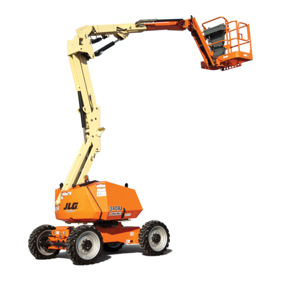
Summary of Contents for JLG 340AJ
- Page 1 Service and Maintenance Manual Model 340AJ P/N - 3121259 June 27, 2017...
-
Page 3: A General
Wear gloves to help protect • BATTERY SHOULD ALWAYS BE DISCONNECTEDDURING hands from spraying fluid. REPLACEMENT OF ELECTRICAL COMPONENTS. • KEEP ALL SUPPORT EQUIPMENT AND ATTACHMENTS STOWED IN THEIR PROPER PLACE. • USE ONLY APPROVED, NONFLAMMABLE CLEANING SOL- VENTS. 3121259 – JLG Lift –... - Page 4 INTRODUCTION REVISON LOG Original Issue - May 6, 2011 Revised - January 17, 2012 Revised - July 9, 2013 Revised - June 27, 2017 – JLG Lift – 3121259...
-
Page 5: Table Of Contents
Do NOT Do the Following When Welding on JLG Equipment ....... -
Page 6: Table Of Contents
Assembly ..................3-60 – JLG Lift –... -
Page 7: Table Of Contents
Communications with the JLG Control System ........ -
Page 8: Table Of Contents
Procedure ..................5-85 – JLG Lift –... -
Page 9: Table Of Contents
To Connect the JLG Control System Analyzer........ - Page 10 TABLE OF CONTENTS SECTION NO. TITLE PAGE NO. This page left blank intentionally – JLG Lift – 3121259...
- Page 11 Swing Gear Assembly ................3-59 3121259 – JLG Lift –...
- Page 12 Master Cylinder ..................5-14 viii – JLG Lift – 3121259...
- Page 13 Analyzer Top Level Menu................6-20 3121259 – JLG Lift –...
- Page 14 Hydraulic Schematic - Sheet 2 of 2 ..............7-31 – JLG Lift –...
- Page 15 LIST OF FIGURES FIGURE NO. TITLE PAGE NO. This page left blank intentionally 3121259 – JLG Lift –...
- Page 16 System Startup Checks ................6-17 – JLG Lift –...
- Page 17 Overload Variations ................6-89 3121259 – JLG Lift – xiii...
- Page 18 LIST OF TABLES TABLE NO. TITLE PAGE NO. This page left blank intentionally – JLG Lift – 3121259...
-
Page 19: Operating Specifications
19’ 11" (6.06 m) Firing Order 1-2-3 Output 24.8 hp (18.5 kW) Machine Width 6’ 4" (1.93 m) Low Idle RPM 1200 ± 50 Wheel Base 6’ 2" (1.87 cm) High Idle RPM 3000± 50 3121259 – JLG Lift –... -
Page 20: Hydraulic Oil
NOTE: Aside from JLG recommendations, it is not advisable to mix oils of different brands or types, as they may not con- tain the same required additives or be of comparable vis- cosities. -
Page 21: Function Speeds
Jib Down 15-21 Lower Lift Up 15-21 Lower Lift Down 14-20 High Drive Forward & Reverse 42-47 (2.9-3.2 MPH) (200 Feet) Drive Above Horizontal Forward & Reverse 57-85 (0.4-0.6 MPH [0.6- (50 Feet) (CE) 0.9 kph]) 3121259 – JLG Lift –... - Page 22 SECTION 1 - SPECIFICATIONS Figure 1-1. Operator Maintenance and Lubrication Diagram – JLG Lift – 3121259...
-
Page 23: Operator Maintenance
The following numbers correspond to those in Figure 1-1., Operator Maintenance and Lubrication Diagram. Table 1-11. Lubrication Specifications SPECIFICATIONS Bearing Grease (JLG Part No. 3020029) Mobilith SHA 460. Hydraulic Oil. API service classification GL-4, e.g. Mobilfluid 424. EPGL Extreme Pressure Gear Lube (oil) meeting API Service Classification GL- 5 or Mil-Spec Mil-L-2105. - Page 24 300 hrs. thereafter. Interval - Check level daily; change every 500 hours or Comments - For breather element, twist top to replace. six months, whichever comes first. Adjust final oil level by mark on dipstick. – JLG Lift – 3121259...
- Page 25 Lube Point(s) - Fill Cap/Spin-on Element Capacity - 3.1 Quarts (3 L) w/Filter Lube - EO Interval - Check level daily; change every 500 hours or six months, whichever comes first. Adjust final oil level by mark on dipstick. 3121259 – JLG Lift –...
- Page 26 SECTION 1 - SPECIFICATIONS Figure 1-2. Torque Chart - Sheet 1 of 5 - (SAE Fasteners) – JLG Lift – 3121259...
- Page 27 SECTION 1 - SPECIFICATIONS Figure 1-3. Torque Chart - Sheet 2 of 5 - (SAE Fasteners) 3121259 – JLG Lift –...
- Page 28 SECTION 1 - SPECIFICATIONS Figure 1-4. Torque Chart - Sheet 3 of 5 - (SAE Fasteners) 1-10 – JLG Lift – 3121259...
- Page 29 SECTION 1 - SPECIFICATIONS Figure 1-5. Torque Chart - Sheet 4 of 5 - (METRIC Fasteners) 3121259 – JLG Lift – 1-11...
- Page 30 SECTION 1 - SPECIFICATIONS Figure 1-6. Torque Chart - Sheet 5 of 5 - (METRIC Fasteners) 1-12 – JLG Lift – 3121259...
-
Page 31: Annual Machine Inspection
Trained Service Technician as a person who has successfully pleted before placing the machine into service. completed the JLG Service Training School for the subject JLG product model. Reference the machine Service and Mainte- Preparation, Inspection, and Maintenance... -
Page 32: Safety And Workmanship
Prior to each sale, lease, or Owner, Dealer, or User Qualified JLG Mechanic Service and Maintenance Manual rental delivery. and applicable JLG inspection form. Frequent Inspection In service for 3 months or 150 hours, whichever Owner, Dealer, or User Qualified JLG Mechanic Service and Maintenance Manual comes first;... -
Page 33: Component Disassembly And Reassembly
If it becomes necessary to hand-fabricate a gasket, use solvent. Lubricate components, as required, to aid gasket material or stock of equivalent material and thickness. assembly. Be sure to cut holes in the right location, as blank gaskets can cause serious system damage. 3121259 – JLG Lift –... -
Page 34: Lubrication And Servicing
NOTE: Metal particles may appear in the oil or filters of new machines due to the wear-in of meshing components. – JLG Lift – 3121259... -
Page 35: Cylinder Drift
Results of these effects are related to several factors including cylinder length and change in temperature over the time the cylinder remains stationary. 3121259 – JLG Lift –... -
Page 36: Pins And Composite Bearing Repair Guidelines
2. Filament wound bearings should be replaced if any of • Ground only to structure being welded. the following is observed: Do NOT Do the Following When Welding on JLG a. Frayed or separated fibers on the liner surface. b. Cracked or damaged liner backing. - Page 37 1,2,5 Hood, Hood Props, Hood Latches 1,2,5 Chassis Assembly Tires 16,17,18 16,17,18 Wheel Nuts/Bolts Wheel Bearings 14,24 Oscillating Axle/Lockout Cylinder Systems Outrigger or Extendable Axle Systems Steer Components Spindle Thrust Bearing/Washers Drive Motors Drive Hubs 3121259 – JLG Lift –...
- Page 38 1,97 Hydraulic Fluid 7,11 7,11 Electrical Connections 1,20 Instruments, Gauges, Switches, Lights, Horn 5,23 General Operation and Safety Manuals in Storage Box ANSI and AEM Manuals/Handbooks Installed (ANSI Markets Only) Capacity Decals Installed, Secure, Legible – JLG Lift – 3121259...
- Page 39 Function Test of All Systems 21, 22 Paint and Appearance Stamp Inspection Date on Frame Notify JLG of Machine Ownership Footnotes: Prior to use each day; or at each Operator change Prior to each sale, lease, or delivery In service for 3 months or 150 Hours; or Out of service for 3 months or more; or Purchased used...
- Page 40 SECTION 2 - GENERAL HYDRAULIC FLUID OPERATION CHART NOTICE: MACHINE OPERATION USING NON-JLG APPROVED HYDRAULIC FLUIDS OR OPERATION OUTSIDE OF THE TEMPERATURE BOUNDARIES OUTLINED IN THE "HYDRAULIC FLUID OPERATION CHART" MAY RESULT IN PREMATURE WEAR OR DAMAGE TO COMPONENTS OF THE HYDRAULIC SYSTEM.
- Page 41 SECTION 2 - GENERAL NOTICE: MACHINE OPERATION USING NON-JLG APPROVED ENGINE OIL OR OPERATION OUTSIDE OF THE TEMPERATURE BOUNDARIES OUTLINED IN THE "ENGINE OIL OPERATION CHART" MAY RESULT IN PREMATURE WEAR OR DAMAGE TO COMPONENTS OF THE ENGINE. 1001120074-A Figure 2-2. Engine Oil Operation Chart - GM...
- Page 42 SECTION 2 - GENERAL NOTES: 2-12 – JLG Lift – 3121259...
-
Page 43: Tires And Wheels
Please refer to the 2. Tighten nuts in the following sequence. JLG Parts Manual for the part number of the approved tires for a particular machine model. If not using a JLG approved... -
Page 44: Drive Orientation System
Max. Speed Boom Position Drive Selection Drive is Actuated Displacement Dividers MPH (kph) Max Speed High-3000 RPM Bypassed 3.1 (4.9) In Transport Mid Engine Mid-1800 RPM Engaged 0.96 (1.5) Max Torque High-3000 RPM Engaged 1.5 (2.4) – JLG Lift – 3121259... -
Page 45: Drive Motor
4. Fit the channel plate (23) so the o-ring groove is 16. Remove the o-ring (19). upwards and the check valve holes line up with the through hole in the gear set. 17. Remove the cardan shaft (18). 5. Install the balls (35). 3121259 – JLG Lift –... - Page 46 55 to 59 ft.lbs. (75 to 80 Nm). 9. Install the guide pin (27) in the end cover (32). 10. Install the balance plate in the end cover (32). Figure 3-1. Drive Motor Special Tools – JLG Lift – 3121259...
- Page 47 20. Gear Set 25. Channel Plate 30. Spacer 35. Ball 16. Mounting Flange 21. Not Used 26. Stop Ring 31. Crinkle Washer 17. O-ring 22. Valve Drive 27. Disc Valve 32. End Cover Figure 3-2. Drive Motor 3121259 – JLG Lift –...
- Page 48 SECTION 3 - CHASSIS & TURNTABLE – JLG Lift – 3121259...
- Page 49 SECTION 3 - CHASSIS & TURNTABLE 3121259 – JLG Lift –...
- Page 50 SECTION 3 - CHASSIS & TURNTABLE – JLG Lift – 3121259...
- Page 51 SECTION 3 - CHASSIS & TURNTABLE 3121259 – JLG Lift –...
-
Page 52: Drive Hub
3,625 psi (250 bar) maximum o-ring check. If brake does not release at these pressure values, brake has to be inspected, repaired or replaced. NOTE: Failure to perform this test may result in damaged or inef- fective brake parts. 3-10 – JLG Lift – 3121259... -
Page 53: Measuring Rolling Torque
3. Remove Retaining Ring (6G) by prying the open end of retaining ring out of the groove in the Ring Gear (1E) with a screwdriver, then grasp the loose end with pliers and pull the retaining ring completely out of the groove. 3121259 – JLG Lift – 3-11... - Page 54 Figure 3-7. Main Disassembly - Figure 1 9. Input Shaft 1E. Ring Gear 11. Sun Gear 4E. Planet Shaft 18. O-ring 4F. Planet Gear 19. Bolt 4G. Roll Pin 4H. Thrust Washer Figure 3-8. Main Disassembly - Figure 2 3-12 – JLG Lift – 3121259...
-
Page 55: Housing-Spindle Disassembly
The holes will need to be cleaned up prior to removing the set screws. 3. While supporting the unit on Housing (1D) flange, press Spindle (1 A) out of housing. 3121259 – JLG Lift – 3-13... - Page 56 SECTION 3 - CHASSIS & TURNTABLE 1A. Spindle 1B. Lip Seal 1C. Ball Bearing 1D. Housing 1F. Bearing Nut 1G. Setscrew 1H. Stud Figure 3-10. Housing-Spindle 3-14 – JLG Lift – 3121259...
-
Page 57: Spindle-Brake Subassembly Disassembly
Ball Bearing (8B) out of mounting adaptor coun- terbore, and check Quad Seal (1K) and O-Ring (8F). 1K. Quad Seal 1N. Mounting Adaptor 8B. Ball Bearing 8C. Retaining Ring 8F. O-ring Figure 3-12. Spindle-Brake Subassembly - Figure 2 3121259 – JLG Lift – 3-15... -
Page 58: Cover Disassembly
10. Knock Ball Bearing (8B) out of Spindle (1A) counterbore if needed. 11. Remove Pressure Plug (22) and Pipe Plug (12) from Spin- dle (1 A) if applicable. This completes the Spindle-Brake Subassembly Disassembly. 3-16 – JLG Lift – 3121259... - Page 59 SECTION 3 - CHASSIS & TURNTABLE 2. Thrust Spacer 6A. Cover 6B. Disengage Cap 6C. Bolt 6D. Dowel Pin 6E. O-ring 6F. Pipe Plug 6K. O-ring Figure 3-14. Cover 3121259 – JLG Lift – 3-17...
-
Page 60: Planet Gear Subassembly
4B. Thrust Washer 4C. Needle Bearing 4D. Thrust Spacer 4F. Planet Gear Figure 3-15. Planet Gear 3-18 – JLG Lift – 3121259... -
Page 61: Spindle-Brake Subassembly
1A. Spindle 8A. Brake Piston 8B. Ball Bearing 8D. O-ring 8E. Backup Ring 8F. O-ring 8H. Backup Ring 8J. Brake Rotor 8K. Brake Stator 8L. Spring 8M. Spring 21. Bolt Figure 3-16. Spindle-Brake Figure 1 3121259 – JLG Lift – 3-19... - Page 62 Spindle (1A) until it contacts Brake Stator (8K). 14. Insert twelve Springs (8L) into Brake Piston (8A) holes and then install the smaller twelve Springs (8M) into the Springs (8L) already installed into the brake piston. 3-20 – JLG Lift – 3121259...
-
Page 63: Housing-Spindle Subassembly
Screws (1G) so the nut will not loosen. 4. Secure Housing (1D) and press Studs (1H) into housing. 1A. Spindle 1B. Lip Seal 1C. Ball Bearing 1D. Housing 1F. Bearing Nut 1G. Setscrew 1H. Stud Figure 3-19. Housing-Spindle 3121259 – JLG Lift – 3-21... -
Page 64: Housing-Ring Gear Subassembly
Step (2) on Spindle (1A). The end of the 1E. Ring Gear 4E. Planet Shaft 4F. Planet Gear 4G. Roll Pin 4H. Thrust Washer 9. Input Shaft 11. Sun Gear 18. O-ring 19. Bolt Figure 3-20. Housing Ring Gear Subassembly 3-22 – JLG Lift – 3121259... -
Page 65: Cover Subassembly
Housing (1D) and Ring Gear (1E). 2. Thrust Spacer 6A. Cover 6B. Disengage Cap 6C. Bolt 6D. Dowel Pin 6E. O-ring 6F. Pipe Plug 6K. O-ring Figure 3-21. Cover 3121259 – JLG Lift – 3-23... -
Page 66: Main Assembly
5. Install O-Ring Pipe Plugs (6F) into Cover (6A). The plugs should be hand tight. The Cover Subassembly is now complete. 6. Cover 6G. Retaining Ring 15. ID Plate 17. O-ring Figure 3-22. Main Assembly 3-24 – JLG Lift – 3121259... -
Page 67: Integral Brake Check Procedure
3. Bleed brake. Increase hydraulic pressure gradually while trying to rotate the input until brake just starts to release. Note this pressure. Make sure the pressure falls into the appropriate range below. BRAKE CODE INITIAL RELEASE PRESSURE RANGE (psi) 240-260 3121259 – JLG Lift – 3-25... - Page 68 1M THRUST WASHER 6C BOLT 8H BACK-UP RING 21 BOLT 1N MOUNTING ADAPTOR 6D DOWEL PIN 8J BRAKE ROTOR 22 PRESSURE PLUG 2 THRUST SPACER 6E O-RING 8K BRAKE STATOR Figure 3-23. Drive Hub Assembly 3-26 – JLG Lift – 3121259...
- Page 69 SECTION 3 - CHASSIS & TURNTABLE Figure 3-24. Bearing Pressing Tool 3121259 – JLG Lift – 3-27...
- Page 70 SECTION 3 - CHASSIS & TURNTABLE Figure 3-25. Seal Pressing Tool Figure 3-26. Drift Pin for Lining Up Thrustwashers with Output Planet Gear 3-28 – JLG Lift – 3121259...
- Page 71 SECTION 3 - CHASSIS & TURNTABLE 3121259 – JLG Lift – 3-29...
-
Page 72: Oscillating Axle System
ARM WILL BE ON THE RAMP WHEN THE MACHINE IS IN THE STOWED POSITION SWITCH #1 LOCATED CLOSET TO BEARING, ARM WILL BE IN THE VOID WHEN THE MACHINE IS IN THE STOWED POSITION Figure 3-28. Axle Oscillation Switches 3-30 – JLG Lift – 3121259... - Page 73 SECTION 3 - CHASSIS & TURNTABLE 3121259 – JLG Lift – 3-31...
-
Page 74: Chassis Tilt Indicator System
3.0° angle is set by choosing the desired market selection for 0.5 degree smaller than the required angles to account for cal- the machine based on machine setup using the JLG Analyzer. ibration and sensor variation. The 5.0°/3.0° angle is used to warn the operator of an excessive The machine’s chassis tilt is measured by a pair of fluid-based... - Page 75 Disassemble unit, identify and remedy cause and repair, replacing parts as necessary. 3. Lack of pumping pressure Check for and repair worn pump. 4. Excessive binding or loading in system external to motor unit. Locate source and eliminate cause. 3121259 – JLG Lift – 3-33...
-
Page 76: Removal
• As you disassemble the motor clean all parts, except seals, in clean petroleum-based solvent, and blow them dry. PETROLEUM-BASE SOLVENTS ARE FLAMMABLE. BE EXTREMELY CAREFUL WHEN USING ANY SOLVENT. EVEN A SMALL EXPLOSION OR FIRE COULD CAUSE INJURY OR DEATH. 3-34 – JLG Lift – 3121259... -
Page 77: Disassembly And Inspection
IF THE MOTOR IS NOT FIRMLY HELD IN THE VISE, IT COULD BE DISLODGED priate 1/2 or 9/16 inch size socket. Inspect bolts for dam- DURING THE SERVICE PROCEDURES, CAUSING INJURY. aged threads, or sealing rings, under the bolt head. Replace damaged bolts. 3121259 – JLG Lift – 3-35... - Page 78 10. Drive Link 15. Thrust Bearing 20. Dirt & Water Seal 25. Backup Washer 5. Commutator 8B. Stator Half 11. Thrust Bearing 16. Seal 21. Not Used Figure 3-32. Swing Motor - Exploded View 3-36 – JLG Lift – 3121259...
- Page 79 (5) is normal. Discoloration would indicate excess fluid temperature, thermal shock, or excess speed and require system investigation for cause and close inspection of end cover, commutator, manifold, and rotor set. 3121259 – JLG Lift – 3-37...
- Page 80 NOTE: A polished pattern on the wear plate from rotor rotation is normal. 3-38 – JLG Lift – 3121259...
- Page 81 Inspect drive link for cracks and worn or damaged splines. No percep- tible lash (play) should be noted between mating spline parts. Remove and discard seal ring (4) from housing (18). 3121259 – JLG Lift – 3-39...
- Page 82 0.020 inches (0.51 mm) diametrically, replace coupling required. shaft. NOTE: A slight "polish" is permissible in the shaft bearing areas. Anything more would require coupling shaft replacement. 15. Remove and discard seal ring (4) from housing (18). 3-40 – JLG Lift – 3121259...
- Page 83 (19) in relation to the beginning of bearing/bushing counter bore should be measured and noted before removing the bearings/bushings. This will facilitate the correct reassembly of new bearings/bushings. 3121259 – JLG Lift – 3-41...
-
Page 84: Assembly
Blow them dry with compressed air. Remove any paint chips from mating surfaces of the end cover, commuta- tor set, manifold rotor set, wear plate and housing and from port and sealing areas. 3-42 – JLG Lift – 3121259... - Page 85 (19). 5. Assemble a new backup ring (17), new backup washer (25) and new seal (16) with the seal lip facing toward the inside of the motor, into their respective counterbores in housing (18). 3121259 – JLG Lift – 3-43...
- Page 86 (12). The coupling shaft must rotate smoothly on the thrust bearing package. 8. Be sure that a generous amount of clean corrosion resis- tant grease has been applied to the lower (outer) hous- ing bearing/bushing (19). Install the coupling shaft (12) 3-44 – JLG Lift – 3121259...
- Page 87 NOTE: Use any alignment marks put on the coupling shaft and drive link before disassembly to assemble the drive link splines in their original position in the mating coupling shaft splines. 3121259 – JLG Lift – 3-45...
- Page 88 The polished impression left on the manifold by the rotor set is another indication of which surface must contact the rotor set. 3-46 – JLG Lift – 3121259...
- Page 89 NOTE: If the end cover has a valve (24) or has five bolt holes, use the line you previously scribed on the cover to radially align the end cover into its original position. 3121259 – JLG Lift – 3-47...
-
Page 90: One Piece Stator Construction
180 degrees apart to retain stator and wear plate stationary. 3. Assemble the rotor, counterbore down if applicable, into stator, and onto wear plate (9) with rotor splines into mesh with drive link (10) splines. 3-48 – JLG Lift – 3121259... -
Page 91: Two Piece Stator Construction
THE STATOR HALF MUST BE REASSEMBLED IN THEIR RESPECTIVE STATOR HALF FOR THE ROTOR SET TO FUNCTION PROPERLY. 6. Remove the two assembled bolts (1) if used to retain sta- tor and wear plate. Go to assembly procedure #15, to continue assembly. 3121259 – JLG Lift – 3-49... -
Page 92: Final Checks
STRUCTURE WEIGHS APPROXIMATELY 7,000 LBS. (3175 KG). 2. Secure the swing motor to the swing drive assembly with the retaining bolts. Apply threadlocker JLG P/N 0100019 to the threads of the retaining bolts and torque to 85 ft.lbs. (115 Nm). - Page 93 SECTION 3 - CHASSIS & TURNTABLE 3. Install eyebolts as specified in Figure 3-33., Eyebolt for Counterweight in the counterweight. 4. Securely strap the booms together to prevent any movement during the lifting process. 3121259 – JLG Lift – 3-51...
- Page 94 5. If equipped, remove the LP fuel tank on the side of the frame. It may also be desirable to remove the tank retaining brackets to gain additional clearance to work. 3-52 – JLG Lift – 3121259...
- Page 95 NOTE: All measurements shown are in mm. Figure 3-33. Eyebolt for Counterweight 7. Pull out the engine tray as far as it will go. Unbolt the working area. charge filter bracket so it can be moved aside for more 3121259 – JLG Lift – 3-53...
- Page 96 10. Remove the drive orientation and lockout switches so they don’t get broken during the removal procedure. 11. Swing the engine tray back into position and secure it in place with the retaining bolt. 3-54 – JLG Lift – 3121259...
-
Page 97: Installation
6. Coat the bearing bolts with JLG Threadlocker P/N 0100019 and install the remaining bolts securing the turntable to the swing bearing. Tighten the bolts snugly but do not torque them at this time. -
Page 98: Turntable Bearing Mounting Bolt Condition Check
NOTE: This check is designed to replace the existing bearing bolt TURNTABLE REF. torque checks on JLG Lifts in service. This check must be performed after the first 50 hours of machine operation and every 600 hours of machine operation thereafter. If... - Page 99 SECTION 3 - CHASSIS & TURNTABLE POSITION BEARING BODY TO TURNTABLE AS SHOWN (90°) POSITION POINT OF MINIMAL BACKLASH MARKED WITH AN "X" AND ALSO BLUE PAINT, 90° TO THE FRAME IN THIS POSITION. Figure 3-36. Bearing Placement 3121259 – JLG Lift – 3-57...
-
Page 100: Disassembly
Also needed are a shim cover plate and cap. and seal kit (available from the JLG Parts Department), ¾" steel 5. Remove Pinion and Gear assembly (15, 16, 17, 21, 23, 24, rod at least 10" long, LocTite #515, Mobil SHC 007 grease, and 31) from housing. - Page 101 22. Motor Adapter 28. Gasket 5. Bolt 11. Grease Fitting 17. Bearing 23. Face Seal 29. Gasket 6. Bolt 12. Grease Fitting 18. Gear Cap 24. Washer Spacer 30. Screw Figure 3-38. Swing Gear Assembly 3121259 – JLG Lift – 3-59...
- Page 102 Clean extra sealant from surfaces of cover plate. Apply a small amount of grease to this flap. Set this assembly to the side. 3-60 – JLG Lift – 3121259...
- Page 103 1150 BOOM CABLE LOWER UPRIGHT LOWER BOOM HARNESS AC CABLE 1550 AIRLINE (IF EQUIPPED) 1550 NOTE: NUMEROUS COMPONENTS SHOWN TRANSPARENT FOR ROUTING CLARITY Figure 3-39. Cable Installation and Identification - Sheet 1 of 8 3121259 – JLG Lift – 3-61...
- Page 104 MAIN LIFT CYLINDER PRESSURE SECTION ROTATED 28.5° CW (ORIENTATION LOOKING TOWARDS LOWER UPRIGHT) LOWER UPRIGHT NOTE: NUMEROUS COMPONENTS SHOWN TRANSPARENT FOR ROUTING CLARITY Figure 3-40. Cable Installation and Identification - Sheet 2 of 8 3-62 – JLG Lift – 3121259...
- Page 105 HOSE AND CABLE ROUTING TURNTABLE AREA EVERY INTO LOWER BOOM 200-250mm. USE CABLE TIES AS REQUIRED SEE DETAIL NOTE: NUMEROUS COMPONENTS SHOWN TRANSPARENT FOR ROUTING CLARITY Figure 3-41. Cable Installation and Identification - Sheet 3 of 8 3121259 – JLG Lift – 3-63...
- Page 106 TORQUE THREADED STUDS TO 15 Nm (10 ft lbs) ASSEMBLE IN THE FOLLOWING ORDER:U NUT, CLAMP BLOCK, PUSH NUT, COVER, FLANGED NUT DETAIL Figure 3-42. Cable Installation and Identification - Sheet 4 of 8 3-64 – JLG Lift – 3121259...
- Page 107 MAIN BOOM LIMIT SWITCHES MAIN BOOM TO BE 1° BELOW HORIZONTAL TO 3° ABOVE HORIZONTAL TO TRIP SWITCH, 1° TO 4° BELOW HORIZONTAL TO RESET SWITCH Figure 3-43. Cable Installation and Identification - Sheet 5 of 8 3121259 – JLG Lift – 3-65...
- Page 108 AC CABLE BOOM CABLE MAIN LIFT CYLINDER PRESSURE SYSTEM PRESSURE TOWER LIFT CYLINDER PRESSURE TOWER LIFT CYLINDER TANK SYSTEM TANK DETAIL SEE DETAIL Figure 3-44. Cable Installation and Identification - Sheet 6 of 8 3-66 – JLG Lift – 3121259...
- Page 109 UPPER BOOM HARNESS CONNECTOR V62 OF CONNECTOR V59 OF UPPER BOOM HARNESS UPPER BOOM HARNESS DETAIL UPRIGHT BACK PLATE SHOWN TRANSPARENT SEE DETAIL Figure 3-45. Cable Installation and Identification - Sheet 7 of 8 3121259 – JLG Lift – 3-67...
- Page 110 UPPER BOOM HARNESS CONNECTOR V56 OF SEE DETAIL UPPER BOOM HARNESS CONNECTOR V55 OF UPPER BOOM HARNESS DETAIL FLY VALVE COVER SHOWN TRANSPARENT Figure 3-46. Cable Installation and Identification - Sheet 8 of 8 3-68 – JLG Lift – 3121259...
-
Page 111: Engine Operating States
& Engine RPM greater than 0) (RPM = 0 for 1/2 second) (RPM = 0 for 1/2 second) ENGINE ENGINE (RPM greater than 800 for 1/4 second) RUNNING STARTING Figure 3-47. Engine Operating State Diagram 3121259 – JLG Lift – 3-69... -
Page 112: Engine Start Conditions
Cranking state. 9. The Engine Shutdown switch must not be activated. 10. The Start Switch has been in the deselected position after the Engine State changes to Engine Stopped from Engine Running or Engine Starting. 3-70 – JLG Lift – 3121259... -
Page 113: Multi-Function Rpm
The Kubota engine is controlled pri- tions exist; marily by the JLG Control System and the GM engine is con- 1. The Engine State is Engine Running. trolled primarily by its own Engine Control Unit (ECU). The following sections describe engine controls that are common 2. -
Page 114: Engine Startup Procedure (Kubota)
3. Attach the fuel hose and secure it in place with the exist- ing hose clamp. 1001107853 C 4. Start the engine and ensure it runs properly and the fuel line does not leak. GROUND PLATFORM Figure 3-50. Low Fuel Indicators 3-72 – JLG Lift – 3121259... -
Page 115: Kubota Engine
Figure 3-51. Engine Oil Pressure Switch Ground Module Engine Oil Pressure Switch Open for Normal Pressure 270 Ohm Closed for Low Pressure J1-15 Input Engine Block Ground Figure 3-52. Engine Oil Pressure Switch Schematic 3121259 – JLG Lift – 3-73... -
Page 116: Coolant Sensor
Figure 3-54. Engine Coolant Sensor Ground Module Engine Oil Pressure Switch Open for Normal Pressure Figure 3-57. Glow Plug Relay 270 Ohm Closed for Low Pressure J1-15 Input Engine Block Ground Figure 3-55. Engine Coolant Sensor Schematic 3-74 – JLG Lift – 3121259... -
Page 117: Engine Speed Actuators
Actuator Relay engine start attempt can be made. Starter Lockout is only applicable for the first glow plug cycle. Figure 3-58. Engine Throttle Actuator Schematic 3121259 – JLG Lift – 3-75... -
Page 118: Engine Start
The Kubota fuel pump is mechanical and has no interaction energizes the starter solenoid. with the JLG Control System. Shutdown If the JLG Control System determines that the engine should be shut down and not allowed to run, the Ground Module Starter Ground Module takes the following steps to shut down the engine. - Page 119 2. Coolant Recovery Tank 6. Main Pump 9. Air Filter 12. Full Speed Relay 3. Alternator 7. Gear Pump 10. Muffler 13. Glow Plug Relay 4. Oil Filter Figure 3-62. Kubota Engine - Sheet 1 of 4 3121259 – JLG Lift – 3-77...
- Page 120 9. Fuel Tank 2. Muffler 6. Fuel Filter/ 8. Fuel Level 10. Radiator 3. Main Pump Water Separator Sending Unit 11. Pressure Cap 4. Gear Pump Figure 3-63. Kubota Engine - Sheet 2 of 4 3-78 – JLG Lift – 3121259...
- Page 121 2. Radiator Mount 5. Engine Harness 8. Glow Plug Relay 11. Main Pump 13. Coolant Recovery Tank 3. Engine Oil Filter 6. Starter Relay 9. Starter Figure 3-64. Kubota Engine - Sheet 3 of 4 3121259 – JLG Lift – 3-79...
- Page 122 9. Fuel Supply Line 12. Fuel Tank 3. Gear Pump 7. Positive Battery Terminal 10. Fuel Return Line 13. Fuel Level Sensor 4. Negative Battery Terminal Figure 3-65. Kubota Engine - Sheet 4 of 4 3-80 – JLG Lift – 3121259...
-
Page 123: Gm Dual Fuel Engine
Communications with the JLG Control System The Ground Module calculates the engine coolant tempera- ture based on information sent to it by the engine ECU. The JLG Control System communicates with the GM engine by sending the following control messages from the Ground Fuel Select Module to the engine’s ECU:... - Page 124 1. Fuel Tank 5. Starter 8. Battery 2. Coolant Recovery Tank 6. Main Pump 9. Muffler 3. Radiator 7. Gear Pump 10. Fuel Mixer 4. Oil Filter Figure 3-66. GM Engine - 1 of 6 3-82 – JLG Lift – 3121259...
- Page 125 1. Coolant Recovery Tank 5. Negative/Ground Terminal 8. Gear Pump 2. Fuel Tank 6. Positive Terminal 9. Battery 3. Radiator 7. Main Pump 10. Muffler 4. Oil Filter Figure 3-67. GM Engine - 2 of 6 3121259 – JLG Lift – 3-83...
- Page 126 10. Radiator 2. Supply Fuel Hose 5. Fuel Pump Harness 8. Muffler 11. Carbon Cannister 3. Return Fuel Hose 6. Air/Fuel Mixer 9. Fuel Level Sensor Figure 3-68. GM Engine - 3 of 6 3-84 – JLG Lift – 3121259...
- Page 127 18. Engine Oil Fill Cap 4. Main Pump 9. Positive Battery Cable 14. Fuel Mixer 5. Gear Pump 10. Positive Battery Post 15. Fuel Level Sensor Figure 3-69. GM Engine - 4 of 6 3121259 – JLG Lift – 3-85...
- Page 128 8. Fuel Pump 2. Fuel Lock-off Valve 6. Fuel Pump Harness 9. Return Port 3. Muffler 7. Fuel Filter 10. Supply Port 4. Air Mixer Valve Figure 3-70. GM Engine - 5 of 6 3-86 – JLG Lift – 3121259...
- Page 129 6. Fuel Level Sensor 9. Coolant Recovery Tank 12. Fuel Lock-off Valve 3. Gear Pump 7. Fuel Tank 10. Engine Oil Filler Cap 13. Relays 4. Battery Figure 3-71. GM Engine - 6 of 6 3121259 – JLG Lift – 3-87...
- Page 130 Injector Driver 3 Open Injector Driver 3 Shorted Injector Driver 4 Open Injector Driver 4 Shorted Crank Sync Noise Crank Loss Cam Sync Noise Cam Sensor Loss Gasoline Cat Monitor 520211 Oil Pressure Low 3-88 – JLG Lift – 3121259...
- Page 131 CAN Rx Failure 1628 CAN Address Conflict Failure 1629 Loss of TSC 1 2111 Unable to Reach Lower TPS 2112 Unable to Reach Higher TPS 2135 TPS 1/2 Simultaneous Voltages 2229 BP Pressure High 3121259 – JLG Lift – 3-89...
-
Page 132: Fuel Reserve / Cut-Out System
The machine will then stay in this mode the platform. It is controlled by a switch in the platform. until the fuel level is returned to a level above 1.3 gallons (4.9 CONTROL BOX GENERATOR ASSEMBLY VOLTAGE REGULATOR Figure 3-72. Generator 3-90 – JLG Lift – 3121259... -
Page 133: Counterweight
If the counterweight has been removed, ensure the retaining bolts are torqued to the proper value as shown in Figure 3-73., Counterweight Bolt Torque. Torque to 150 ft.lbs. (204 Nm) ± 3% Figure 3-73. Counterweight Bolt Torque 3121259 – JLG Lift – 3-91... - Page 134 SECTION 3 - CHASSIS & TURNTABLE NOTES: 3-92 – JLG Lift – 3121259...
-
Page 135: Platform Control Enable System
Cap or plug all openings. NOTE: When removing the retaining pin from the rod end of the telescope cylinder, make sure the cylinder is properly sup- ported. 3121259 – JLG Lift –... - Page 136 NOTE: The telescope cylinder weighs approximately 53 lbs. (24 kg). NOTE: The fly boom section weighs approximately 188 lbs. (85 kg). 8. Using a suitable lifting device, remove fly boom from boom section. – JLG Lift – 3121259...
-
Page 137: Inspection
SECTION 4 - BOOM & PLATFORM Inspection 3. Using JLG P/N 0100011 thread locking compound or equivalent, install the front wear pads and shims as 1. Inspect all boom pivot pins for wear, scoring or other noted during disassembly on the base boom section. - Page 138 SECTION 4 - BOOM & PLATFORM 5. Align the telescope cylinder rod end with the corre- 6. Using JLG P/N 0100011 thread locking compound or equivalent, secure the rear of the telescope cylinder to sponding hole in the fly boom section. If necessary,...
- Page 139 SECTION 4 - BOOM & PLATFORM 1. Master Cylinder 6. Upper Upright 2. Upper Lift Cylinder 7. Mid Boom Link 3. Jib 8. Mid Boom 4. Main Boom 9. Jib Cylinder 5. Level Cylinder Figure 4-1. Main Boom Assembly 3121259 – JLG Lift –...
- Page 140 SECTION 4 - BOOM & PLATFORM 1. Rotator 5. Hose Carrier 2. Jib Cylinder 6. Lower Jib Link 3. Jib Pivot 7. Upper Jib Link 4. Platform Support Figure 4-2. Jib/ Platform Support – JLG Lift – 3121259...
-
Page 141: Boom Cleanliness Guidelines
“puddling” of water has occurred, and that the boom internal components are 1. JLG recommends the use of the JLG Hostile Environment dry prior to operating the machine. Make sure you com- Package if available to keep the internal portions of a... - Page 142 SECTION 4 - BOOM & PLATFORM – JLG Lift – 3121259...
- Page 143 SECTION 4 - BOOM & PLATFORM 3121259 – JLG Lift –...
-
Page 144: Rotary Actuator
Applying pressure to the opposite port will return the piston and shaft to their original starting positions. Figure 4-5. Actuator Theory of Operation 4-10 – JLG Lift – 3121259... -
Page 145: Tools Required
3. Round off all sharp edges of the heated screwdriver to a assembly. polished finish. The tool may be modified slightly to your own personal preference. TO AVOID INJURY BE CAREFUL WHEN HANDLING THE SCREWDRIVER WHEN HOT. 3121259 – JLG Lift – 4-11... - Page 146 2. Remove the cap screws (113) that cover the end cap lock pins (109). 3. Using a 1/8" (3 mm) drill bit, drill a hole in the center of each lock pin to a depth of approximately 3/16" (5 mm). 4-12 – JLG Lift – 3121259...
- Page 147 103.2 . Washer 202. T-Seal 304. Thrust Washer 420.1 Bushing 3. Piston Sleeve 204. O-ring 420.2 Bushing 4. End Cap 205. Cup Seal 421.1 Bushing 207. Backup Ring 304.1. Wiper Seal 106 1 PortPlug 3121259 – JLG Lift – 4-13...
- Page 148 3. Piston Sleeve 106.1. Port Plug 204. O-ring 4. End Cap 106.2. Port Plug 205. Cup Seal 109 . Lock Pin 207. Backup Ring 113. Capscrew 304.1. Exclusion Seal Figure 4-7. Rotary Actuator - Exploded View 4-14 – JLG Lift – 3121259...
- Page 149 10. Prior to removing the shaft (2), use a felt marker to marks can be used, but it is easier to highlight punched clearly indicate the timing between shaft and piston sleeve (3). This will greatly simplify timing when the actuator is reassembled. 3121259 – JLG Lift – 4-15...
- Page 150 TO AVOID DAMAGE TO MACHINED PARTS CAREFULLY REMOVE SEALS USING aged. REMOVAL TOOLS WITH ROUNDED EDGES. 16. Remove the wear guide (302) from the end cap (4) and shaft (2). 4-16 – JLG Lift – 3121259...
- Page 151 2. Carefully inspect all critical areas for any surface finish abnormalities: Seal grooves, bearing grooves, thrust sur- faces, shaft surface, housing bore and gear teeth. SMALL OR MINOR SURFACE SCRATCHES CAN BE CAREFULLY POLISHED. 3121259 – JLG Lift – 4-17...
- Page 152 (4). 3. Install the exclusion seal (304.1) into the appropriate grooves on the shaft (2) and end cap (4) around the out- side edge of the thrust washer (304). 4-18 – JLG Lift – 3121259...
- Page 153 Make sure the wedged ends overlap correctly. Insert the other back up ring in upper groove. Repeat both of these steps for the outer seal (202). 3121259 – JLG Lift – 4-19...
- Page 154 Do not engage the piston gear bore. teeth yet. AS THE SHAFT IS ROTATED, BE CAREFUL NOT TO DISENGAGE THE PISTON AND HOUSING GEARING. 4-20 – JLG Lift – 3121259...
- Page 155 16. Thread the end cap (4) onto the shaft (2). Make sure the wear guide remains in place on the end cap as it is 19. Insert the set screws (113) over the lock pins. Tighten to threaded into the housing (1). 25 in-lbs. (2.8 Nm). 3121259 – JLG Lift – 4-21...
-
Page 156: Greasing Thrust Washers
25 in-lbs. (2.8 Nm). Repeat the test procedure outlined above for the other port. If there is an internal leak, disassemble, inspect and repair. 4-22 – JLG Lift – 3121259... - Page 157 SECTION 4 - BOOM & PLATFORM Figure 4-8. Rotator Counterbalance Valve 3121259 – JLG Lift – 4-23...
-
Page 158: Installation And Bleeding
1/4 gallon of fluid is pumped into the container. 4. Repeat steps 2 & 3. After the last 1/2 gallon is purged, close both bleed nipples before rotating away from the end position. 4-24 – JLG Lift – 3121259... -
Page 159: Troubleshooting
Conduct the inter- nal leakage test as described in the Testing section on page 24 of this manual. c. Air in actuator c. Purge air from actuator. See bleeding procedures 3121259 – JLG Lift – 4-25... - Page 160 NOTE: If any rotator bolts are replaced, all bolts on the rotator should be retorqued. Torque to 35 ft.lbs. (48 Nm) Loctite #242 Torque 250-270 ft. lbs. (340-365 Nm) Check torque every 150 hours of operation Figure 4-9. Platform Support Torque Values 4-26 – JLG Lift – 3121259...
-
Page 161: Lubricating O-Rings In The Hydraulic System
1. Hold the fitting in one hand while using the brush with the other hand to dip into the container. Remove excess hydraulic oil from the brush so an even film of oil is applied on the o-ring. 3121259 – JLG Lift –... -
Page 162: Dip Method
3. O-ring Boss type fittings will require more pressure in able to immerse more of the fitting into the saturated sponge. This will also cause more oil to be dispersed from the sponge. – JLG Lift – 3121259... -
Page 163: Hydraulic Cylinders
Check the oil leakage at the rod area. Refer to Figure 5-1., Acceptable Oil Leakage on Cylinder Rod. Inspection of internal leakage Leakage Unit: ml/ 10 minutes Bore (mm) Leakage (ml) Bore (mm) Leakage (ml) Bore (mm) Leakage (ml) Remark 12.6 15.6 3121259 – JLG Lift –... - Page 164 Check the oil leakage status on the rod surface with a flow of 20cc - 40cc. Oil leakage in an amount as shown in example A is unac- ceptable. Examples B-G are acceptable. OIL RING Figure 5-1. Acceptable Oil Leakage on Cylinder Rod – JLG Lift – 3121259...
- Page 165 SECTION 5 - HYDRAULICS Table 5-2. Required Tools Item No. Description Quantity Flat-head Screwdriver 1 Set Allen Wrench Set Vise 1 Set Spanner Wrench Punch 1 Set Torque Wrench Plastic Hammer Crescent Wrench Hera (Seal Disassembly) 3121259 – JLG Lift –...
-
Page 166: Disassembly Procedure
4. Remove the Rod assembly a. Check if the cap or plug has been removed from the cylinder ports. b. Place a suitable container under the cylinder to catch any oil coming out of the cylinder. – JLG Lift – 3121259... - Page 167 PORTED. PLACE SUPPORT UNDER THE BARREL AS SHOWN BELOW. NOTE: If it is not a set screw type, continue with the disassembly of the piston nut. 7. Remove the PISTON NUT, PISTON and GLAND in sequence. 3121259 – JLG Lift –...
- Page 168 Remove the rod seal and backup ring. b. Remove the retaining ring with a flat-head screw- driver prior to removing the dust wiper and remove the dust wiper. c. Remove the o-ring and backup ring. – JLG Lift – 3121259...
- Page 169 Coat the opening with oil to aid in assembly and press the bushing into the rod as shown below. PART 1 2. Gland seal assemblies a. Coat the opening with oil to aid in assembly and press the bushing into place with the proper tool. 3121259 – JLG Lift –...
- Page 170 Install the o-ring into the groove. a. Secure the rod assembly. b. Install the Head onto the rod assembly. Take care as not to damage the lip of the dust wiper and rod seal. c. Assemble Piston. 5-10 – JLG Lift – 3121259...
- Page 171 8 cycles. If it is operated too fast in the beginning, cavitation will result. It is important to make sure all air is cycled from the cylinder. b. Grease the end of the pin. 3121259 – JLG Lift – 5-11...
- Page 172 13. Piston Seal 18. Check Valve 23. Plug 4. Dust Wiper 9. O-ring 14. Wear Ring 19. Plug 24. O-ring 5. Retaining Ring 10. Backup Ring 15. O-ring 20. O-ring Figure 5-2. Tower Lift Cylinder 5-12 – JLG Lift – 3121259...
- Page 173 24. MPR Bearing 4. Dust Wiper 10. Backup Ring 15. O-ring 20. Check Valve 25. Plug 5. Retaining Ring 11. O-ring 16. Nut 21. Plug 26. O-ring 6. Rod Seal Figure 5-3. Upper Lift Cylinder 3121259 – JLG Lift – 5-13...
- Page 174 12. Piston 17. MRP Bearing 3. Gland 8. Dry Bearing 13. Piston Seal 18. Plug 4. Dust Wiper 9. O-ring 14. Wear Ring 5. Retaining Ring 10. Backup Ring 15. O-ring Figure 5-4. Master Cylinder 5-14 – JLG Lift – 3121259...
- Page 175 13. Piston Seal 18. Counterbalance Valve 23. O-ring 4. Dust Wiper 9. O-ring 14. Wear Ring 19. Counterbalance Valve 24. Phase Valve 5. Retaining Ring 10. Backup Ring 15. O-ring 20. Plug Figure 5-5. Level Cylinder 3121259 – JLG Lift – 5-15...
- Page 176 4. Dust Wiper 10. Backup Ring 16. Piston Ring 22. Counterbalance Valve 5. Retaining Ring 11. O-ring 17. Hex Nut 23. Plug 6. Rod Seal 12. Piston 18. MRP Bearing 24. O-ring Figure 5-6. Jib Cylinder 5-16 – JLG Lift – 3121259...
- Page 177 6. Rod Seal 11. Wear Ring 2. Rod 7. Dry Bearing 12. Piston Seal 3. Piston 8. O-ring 13. MRP Bearing 4. Gland 9. Backup Ring 5. Dust Wiper 10. O-ring Figure 5-7. Steer Cylinder 3121259 – JLG Lift – 5-17...
- Page 178 18. O-ring 23. Plug 4. Dust Wiper 9. O-ring 14. Wear Ring 19. Counterbalance Valve 24. Plug 5. Retaining Ring 10. Backup Ring 15. O-ring 20. Counterbalance Valve 25. MRP Bearing Figure 5-8. Telescope Cylinder 5-18 – JLG Lift – 3121259...
- Page 179 12. O-ring 17. Plug 3. Dust Wiper 8. Bleeder 13. Not Used 18. O-ring 4. Rod Seal 9. Plug 14. Not Used 5. Backup Ring 10. O-ring 15. Plug Figure 5-9. Axle Lockout Cylinder 3121259 – JLG Lift – 5-19...
- Page 180 SECTION 5 - HYDRAULICS 1. Return Filter 2. Breather 3. Fill Cap 4. Internal Baffle 5. Drain Plug 6. Oil Level Gauge Figure 5-10. Hydraulic Tank 5-20 – JLG Lift – 3121259...
- Page 181 TORQUE 18-24 FT.LBS. (24 - 32 Nm) ASSEMBLE TO BRACKET WITH MARKING ORIENTED FLY BOOM AS SHOWN CONTROL VALVE TORQUE 10-14 FT.LBS. (14 - 19 Nm) THREADLOCKER P/N 0100011 Figure 5-11. Valve Installation - Sheet 1 of 2 3121259 – JLG Lift – 5-21...
- Page 182 MANUAL PUMP THREADLOCKER P/N 0100011 THREADLOCKER P/N 0100011 FLOW DIVIDER VALVE SECTION D-D VALVE MOUNT PLATE THREADLOCKER P/N 0100011 TORQUE 18-24 FT.LBS. (24 - 32 Nm) Figure 5-12. Valve Installation - Sheet 2 of 2 5-22 – JLG Lift – 3121259...
- Page 183 SECTION 5 - HYDRAULICS 3121259 – JLG Lift – 5-23...
- Page 184 SECTION 5 - HYDRAULICS 5-24 – JLG Lift – 3121259...
- Page 185 SECTION 5 - HYDRAULICS 3121259 – JLG Lift – 5-25...
- Page 186 12 Pressure Compensated Flow 19-21 25.8-28.6 Regulator Valve 13 Pressure Compensator 24-26 32.7-35.4 14 Check Valve 12-14 16.3-19 15 Relief Valve 19-21 25.8-28.6 16 Plug 12-14 16.3-19 1001116487-E Figure 5-16. Main Control Valve Torque Specifications 5-26 – JLG Lift – 3121259...
- Page 187 SECTION 5 - HYDRAULICS LIFT UP TOWER LIFT UP FLOW CONTROL SWING LEFT STEER LEFT SWING RIGHT STEER RIGHT HIGH FLOW DUMP V240 LOW FLOW DUMP Figure 5-17. Main Control Valve Identification 3121259 – JLG Lift – 5-27...
- Page 188 Flow Divider Valve 73-77 99-104 Flow Divider Valve 48-52 65-70 Check Valve 24-26 32.5-35.25 Coil 5.4-6.8 Coil 5.4-6.8 10 Plug 24-26 32.5-35.25 11 Plug 12-14 16.3-19 1001118029-D Figure 5-18. Flow Divider Valve Torque Specifications 5-28 – JLG Lift – 3121259...
- Page 189 PORT #18 (MOTOR, DRIVE) PORT #3 PRIMARY OSCILLATING AXLE VALVE TRACTION SECONDARY BRAKE LOCK OSCILLATING VALVE PORT #5 VALVE AXLE VALVE PORT #7 Figure 5-19. Flow Divider Valve Identification - Sheet 1 of 3 3121259 – JLG Lift – 5-29...
- Page 190 PORT "A" (MOTOR, PORT "A" (MOTOR, DRIVE) DRIVE) PRIMARY SECONDARY OSCILLATING SECONDARY PRIMARY OSCILLATING AXLE VALVE OSCILLATING OSCILLATING AXLE VALVE AXLE VALVE AXLE VALVE Figure 5-20. Flow Divider Valve Identification - Sheet 2 of 3 5-30 – JLG Lift – 3121259...
- Page 191 SECTION 5 - HYDRAULICS V213 V212 BYPASS BRAKE V212 BRAKE OSC AXLE #2 SECONDARY OSC AXLE #1 PRIMARY V213 BYPASS Figure 5-21. Flow Divider Valve Identification - Sheet 3 of 3 3121259 – JLG Lift – 5-31...
- Page 192 (VALVE, UPRIGHT) NOTE: Solenoid Valves are torqued 19-21 ft.lbs. (25.8-28.6 Nm). Coils are torqued 4-5 ft.lbs. (5.4-6.8 Nm). NOTE: Solenoid Coils are rated at 9.8 Ohms. ROTATE 1001116228-C Figure 5-22. Fly Boom Control Valve Identification 5-32 – JLG Lift – 3121259...
- Page 193 TELESCOPE PORT "V1" (VALVE, UPRIGHT) VALVE, UPRIGHT PORT "V1" (TELE CYL) PORT "M2" (VALVE, UPRIGHT) PORT "M1" (VALVE, UPRIGHT) PORT "V2" (VALVE, UPRIGHT) PORT "V2" (TELE CYL) 1001116229-D Figure 5-23. Upright Control Valve Identification 3121259 – JLG Lift – 5-33...
-
Page 194: Drive Pump
A or C and the other half to port B or D. Front and rear sections have independent porting in the options do not use the mechanical feedback link. Figure 5-24. Drive Pump - Cross Sectional View 5-34 – JLG Lift – 3121259... -
Page 195: The System Circuit
Bypass Valve in relief mode order code for pumps with only HPRV is the HPRV setting.The system pressure shown in the order code for pumps with pres- sure limiter and HPRV, is the pressure limiter setting. 3121259 – JLG Lift – 5-35... -
Page 196: Drive Pump
CPRV is set with a flow of 30 l/min [8 US gal/min]. In forward or reverse, charge pressure will be slightly lower than in neutral position. The model code of the pump specifies the charge relief setting. Figure 5-28. Charge pressure relief valve 5-36 – JLG Lift – 3121259... -
Page 197: Electrical Displacement Control (Edc)
NOTE: The neutral position of the control spool does provide a positive preload pressure to each end of the servo piston assembly. 3121259 – JLG Lift – 5-37... - Page 198 (excluding influence of efficiency), is Figure 5-29. EDC-Schematic Diagram NOTE: These symbols are used throughout the Drive Pump illustrations. Figure 5-30. Symbol Chart 5-38 – JLG Lift – 3121259...
- Page 199 1. Pull the shaft with bearing out of the pump. If necessary, tap lightly on the shaft to dislodge it from the internal pump components. DOWEL PINS (D300) ARE A PRESS FIT AND WILL REMAIN IN HOUSING. 3121259 – JLG Lift – 5-39...
- Page 200 NOT AVAILABLE SEPARATELY. CONTROL IS SOLD AS A COMPLETE UNIT ONLY. AUXILIARY PAD OR END COVER REMOVAL REMOVE AUXILIARY PUMP, IF PRESENT. 2. Remove end cover/auxiliary pad screws (K400) using an 8 mm internal hex wrench. 5-40 – JLG Lift – 3121259...
- Page 201 NOTE: HPRV valves may not have the same pressure setting. Tag each valve for reassembly. 2. Remove and discard O-ring (L022). NOTE: Right and left pressure settings are different. Tag each valve for later re-assembly 3121259 – JLG Lift – 5-41...
- Page 202 5. Remove and discard gasket (G150). 6. If necessary, remove bushing (G550) using a suitable puller. 7. Remove locating pins (B010). NOTE: If necessary, use a hook to remove screens (B040) and dis- card. 5-42 – JLG Lift – 3121259...
- Page 203 2. Remove bearings (D075) by sliding them from the Remove the servo piston assembly (E100). swashplate and discard them. DO NOT REUSE SWASHPLATE BEARINGS. SERVO PISTON DISASSEMBLY 1. Remove and discard seals (E025). 2. Remove slider block (EO 15). 3121259 – JLG Lift – 5-43...
- Page 204 Replace any piston assemblies with excessively worn slippers. Check the slipper axial end-play. Replace any piston assem- blies with excessive end-play. 2. Remove the ball guide (C15). 3. Remove the three pins (C25). 5-44 – JLG Lift – 3121259...
- Page 205 If pitting from cavita- tion exists, replace the valve plate. Check for excess wear on the brass running face. If you observe any discoloration or burn marks, replace the valve plate. 3121259 – JLG Lift – 5-45...
- Page 206 Replace O-rings before reassembly. ENDCAP Inspect the endcap. Inspect all machined surfaces for scratches or pits. Carefully check the bearing surface for wear. Inspect valve seats carefully for wear or cracks. Replace if dam- aged. 5-46 – JLG Lift – 3121259...
- Page 207 If necessary, you may remove and clean the control orifices. Use a 3 mm internal hex. wrench Torque to 2.5 Nm [1.8 Ib.ft.]. Remove and replace the screen if contaminated. Screen is not serviceable. 3121259 – JLG Lift – 5-47...
- Page 208 3. Lubricate and install a new O-ring (J260) onto seal car- rier (J275). Press a new seal (J250) into the seal carrier so the solid side of the seal is against the shoulder of the seal carrier. 5-48 – JLG Lift – 3121259...
- Page 209 DO NOT ALLOW LOOSE SERVO PISTON TO DAMAGE INTERNAL MACHINED SUR- FACES OF PUMP. DO NOT DAMAGE SEALS WHEN INSTALLING SERVO CYLINDERS. 3. Install locking plates (E300). Using a 10 mm wrench, install locking plate screws (E350). Torque screws to 13.2-16.1 Nm [9.7-11.9 Ib.ft.]. 3121259 – JLG Lift – 5-49...
- Page 210 (C30), and outer washer (C35) into the cylinder block. Using a press, compress the block spring enough to expose the retaining ring groove. Wind the spiral retain- ing ring (C45) into the groove in the cylinder block. 5-50 – JLG Lift – 3121259...
- Page 211 2. Clean the valve plate (C025) and endcap(G100). 3. Apply a liberal amount of assembly grease to the back- side of the valve plate surface to hold it in place and position on endcap in original position. 3121259 – JLG Lift – 5-51...
- Page 212 Install new outer seal (S300). 4. Lubricate and install thrust washer (K500) in same orien- tation as when it was removed. NOTE: Bump on thrust washer fits into hole in cover. 5-52 – JLG Lift – 3121259...
- Page 213 1. Replace and lubricate O-rings (L060) and backup rings (L068) before reassembly. CHARGE PRESSURE RELIEF VALVE INSTALLATION 1. Install new O-ring (V024). 2. Using a 22 mm wrench, install HPRV valves (L100) and (L200). 3. Torque to 70 Nm [52 Ib.ft.]. 3121259 – JLG Lift – 5-53...
- Page 214 NOTE: If you suspect coil malfunction, remove the coil (D025B) by removing the plastic nut with a 26 mm 12 point socket. Install a new coil and torque the nut to 5 Nm [3.7 ft.lbs.]. 5-54 – JLG Lift – 3121259...
- Page 215 (D250). Torque screws to 13 Nm [10 ft.lbs.]. Follow torque sequence shown. NOTE: If orifices (F100) were removed, reinstall using a 3 mm internal hex wrench.Torque to 2.5 Nm [1.8 ft.lbs.]. 3121259 – JLG Lift – 5-55...
-
Page 216: Port Locations And Gauge Installation
System pressure 600 bar [10,000 psi] 9/16-18 UNF 2B 1/4 internal hex Charge pressure 50 bar [1000 psi] M4,M5 7/16-20 UNF 2B 3/16 internal hex Servo pressure 50 bar [1000 psi] Figure 5-31. Port Locations 5-56 – JLG Lift – 3121259... -
Page 217: Fastener Size And Torque Chart
49 Nm [36 ft.lbs.] D065 7/16-20 3/16 in internal hex 19 Nm [14 ft.lbs.] G250 9/16-18 7 mm internal hex 22-26 Nm [16-20 ft.lbs.] G300/G302 9/16-18 UNF 1/4 in internal hex 42 Nm [30 ft.lbs.] 3121259 – JLG Lift – 5-57... - Page 218 SECTION 5 - HYDRAULICS Figure 5-32. Fasteners and Plugs - Sheet 1 of 2 5-58 – JLG Lift – 3121259...
- Page 219 SECTION 5 - HYDRAULICS Figure 5-33. Fasteners and Plugs - Sheet 2 of 2 3121259 – JLG Lift – 5-59...
-
Page 220: Initial Startup Procedures
Fill inlet line from reservoir to pump. Ensure construc- tion plug in control is closed after filling. 6. Disconnect the pump from all control input signals. 7. Close construction plug removed in step 4. 5-60 – JLG Lift – 3121259... - Page 221 Filter bypass indicator switch Filter switch may be bad Check/replace filter switch. Add gauge to filter bypass port to verify proper fluid flow and verify switch operation by measuring resistance, open resistance=>510 Ohm, closed resistance<=122Ohm 3121259 – JLG Lift – 5-61...
- Page 222 A loose shaft coupling causes excessive noise Replace loose shaft coupling. Shaft alignment Misaligned pump and prime mover shafts create noise Align shafts. Charge/system relief valves Unusual noise may indicate sticking valves. Possible con- Clean/replace valves and test pump. tamination 5-62 – JLG Lift – 3121259...
- Page 223 Clean or replace control screens. Pump inlet vacuum Inlet vacuum is too high resulting in reduced system pres- Measure charge inlet vacuum. Inspect line for proper siz- sure ing. Replace filter. Confirm proper bypass operation. 3121259 – JLG Lift – 5-63...
-
Page 224: Pump Adjustment
Nm [13 lb.ft.]. hydraulic fluid. 5. When you achieve the desired charge pressure setting, remove the gauges and plug the ports. 7. Before re-installing the pump, test for leaks. 5-64 – JLG Lift – 3121259... - Page 225 NOTE: The model code on the serial plate gives the factory setting of the PL (Pressure Limiter).The PL setting is referenced to charge pressure. Subtract charge pressure from system pressure gauge readings to compute the effective PL set- ting. 3121259 – JLG Lift – 5-65...
- Page 226 12 Nm [9 ft.lbs.]. Do not over torque. 7. Shut down the prime mover. Remove gauges and replace plugs. Table 5-15. Pressure Limiter Settings Pressure limiter setting HPRV setting Figure 5-35. Pressure Limiter Adjustment 5-66 – JLG Lift – 3121259...
-
Page 227: Displacement Limiter Adjustment
Adjusting Screw Size and torque per revolution of adjusting screw 13 mm 23Nm[17lb.ft.] 4 mm internal hex 5.1 cm3 [0.31 in3] 13 mm 23Nm 4 mm internal hex 6.0 cm3 [0.37 in3] [17 lb.ft.] 3121259 – JLG Lift – 5-67... -
Page 228: Control Neutral Adjustment
Reconnect the external control input. NOTE: A small pressure differential of 1.5 bar [22 psi] or less is acceptable. Zero differential is usually not possible. 5-68 – JLG Lift – 3121259... -
Page 229: Mechanical Neutral Adjustment
C2. Reverse gauge locations (M4 for M5, MB for MA) from those stated above since the pump is now stroking the other direction. 3121259 – JLG Lift – 5-69... -
Page 230: Removing The Pump
Torque to 2.5 Nm [1.8 lb.ft.]. 8. Install the control module and six cap screws (D250). 9. Using a 5 mm internal hex wrench, torque the cap screws (D250) to 13.5 Nm [10 lb.ft.]. 5-70 – JLG Lift – 3121259... -
Page 231: Control Solenoids
Remove the seal carrier. Remove and discard 7. Install coil using a 12 point 26 mm socket. Torque coil O-ring (J260). Press the seal (J250) out of the carrier and nut to 5 Nm [3.7 ft.lbs.]. discard. 3121259 – JLG Lift – 5-71... - Page 232 7. Install the shaft/bearing assembly into the pump. in] after installation. 8. Lubricate and install a new O-ring (J260) onto seal car- rier (J275). Press a new seal (J250) into the seal carrier. Figure 5-38. Shaft assembly 5-72 – JLG Lift – 3121259...
-
Page 233: Charge Check / Hprv
4. Install HPRVs. Torque to the value in the table below. [38 lb.ft.]. 5. Operate the vehicle/machine through full range of con- 5. Operate vehicle/machine through full range of controls trols to ensure proper operation. Check for leaks. to ensure proper operation. 3121259 – JLG Lift – 5-73... -
Page 234: Pressure Limiter Valve Replacement
4. Replace pressure limiter valve. Torque to 30 Nm [22 lb.ft.]. 5. Operate pump at full range of controls to ensure proper machine operation. Pressure limiter is available as com- plete unit only. O-ring is available separately. 5-74 – JLG Lift – 3121259... - Page 235 2. Remove capscrews. Use a 17 mm socket wrench and loosen the four cap- screws on the cover. Next completely unscrew the cap- screws and remove them. Inspect the threads of the capscrews for damage. 3121259 – JLG Lift – 5-75...
- Page 236 SECTION 5 - HYDRAULICS Figure 5-39. Gear Pump Cutaway 5-76 – JLG Lift – 3121259...
- Page 237 Clean with shop solvent, dry, and set aside. IMPORTANT: DO NOT USE TOOLS WITH SHARP EDGES TO REMOVE THE SEALS, Visually inspect rear cover and seal area. AS DAMAGE TO THE COVER CAN RESULT. After removal, dispose of damaged seals. 3121259 – JLG Lift – 5-77...
- Page 238 1. Prepare the seals. Have the entire seal kit available. Lightly coat all seals with seal grease. The grease is needed to adhere the seals to their grooves. DO NOT INSTALL DRY SEALS. 5-78 – JLG Lift – 3121259...
- Page 239 Inspect the internal and mating surfaces. Ensure the sur- faces are free of burrs and scratches. Check both the bearing block mating surface and the cut-in path. The cut-in path should be no deeper than 0.1 mm (0.004 in). 3121259 – JLG Lift – 5-79...
- Page 240 Ensure that the relative position of the gear Rewash the gears after this operation. mesh is maintained as before disassembly. Misalign- ment of the gear teeth may increase operating noise. 5-80 – JLG Lift – 3121259...
- Page 241 11. Clean the mating surfaces. Remove any excess lubrication and grease from the mat- ing surfaces of the pump body. Ensure that these sur- faces are dry and free of contamination before moving on to the next step. 3121259 – JLG Lift – 5-81...
- Page 242 • Against the direction of the flow if the unit is a unidi- rectional motor. • If the unit is a bidirectional motor the arrow does not appear on the cover. Ensure that all the pressure seals stay in place during this operation. 5-82 – JLG Lift – 3121259...
- Page 243 Then, using a torque wrench, tighten them to the proper torque. Torque 2.5-3.4 Nm (22-30 ft.lbs.). Torque 44-54 Nm (32-40 ft.lbs.). If used, install new o-ring to flange pilot. 3121259 – JLG Lift – 5-83...
- Page 244 If bearing blocks are not worn, replace pressure seals and Reduced "stack-up" will affect seal efficiency possibly to re-torque pump assembly fasteners. the point of seal extrusion. 5-84 – JLG Lift – 3121259...
-
Page 245: Pressure Setting Procedure
The relief valve is located above port “T2”. Acti- vate level up. The pressure read should be 2800 psi +/- 100. To increase, turn clockwise. To decrease, turn coun- ter-clockwise. Re-hose port L1. 3121259 – JLG Lift – 5-85... - Page 246 SECTION 5 - HYDRAULICS Figure 5-40. Oil Sampling Port 5-86 – JLG Lift – 3121259...
-
Page 247: Jlg Control System Analyzer Kit Instructions
SECTION 6 - JLG CONTROL SYSTEM SECTION 6. JLG CONTROL SYSTEM 6.1 JLG CONTROL SYSTEM ANALYZER KIT The JLG designed Control System is a 12 volt based motor con- trol unit installed on the boom lift. INSTRUCTIONS The JLG Control System provides simplicity in viewing and... -
Page 248: Analyzer Menu Structure
(see Figure 6-14., Analyzer Personalities Menu - NOTE: Each module has a label with the JLG part number and a Sheet 1 of 2). These settings can be modified in the Ser- serial number which contains a date code. -
Page 249: Using The Hand Held Analyzer
6.3 USING THE HAND HELD ANALYZER Using the Analyzer With the machine power on and the analyzer connected prop- To Connect the JLG Control System Analyzer erly, the analyzer will display the following: 1. Connect the four pin end of the cable supplied with the... -
Page 250: Changing The Access Level Of The Hand Held Analyzer
SECTION 6 - JLG CONTROL SYSTEM The top level menus are as follows: When a top level menu is selected, a new set of menu items may be offered: for example: HELP SYSTEM DIAGNOSTICS DATALOG SYSTEM TEST VERSIONS OPERATOR ACCESS... -
Page 251: Adjusting Parameters Using The Hand Held Analyzer
SECTION 6 - JLG CONTROL SYSTEM Press ENTER to select the ACCESS LEVEL menu. Adjusting Parameters Using the Hand Held Using the UP or DOWN arrow keys, enter the first digit of the Analyzer password, 3. Once you have gained Service Access, and a personality item is... -
Page 252: Machine Setup
SECTION 6 - JLG CONTROL SYSTEM Machine Setup There are two settings that JLG strongly recommends that you do not change. These settings are so noted below: When a machine digit item is selected, press the UP or DOWN DRIVE MT ELEV MAX (Driving with engine at Max... - Page 253 SECTION 6 - JLG CONTROL SYSTEM Table 6-1. Analyzer Abbreviations Table 6-1. Analyzer Abbreviations ABBREVIATION MEANING ABBREVIATION MEANING GROUND ACCEL ACCELERATE GREEN ACTIVE GROUND MODULE ANALOG DIGITAL CONVERTER COUNT HOURS AMB. AMBIENT HARDWARE ANGLE HWFS HARDWARE FAILSAFE AUXILIARY IN or CURRENT...
- Page 254 SECTION 6 - JLG CONTROL SYSTEM Table 6-1. Analyzer Abbreviations ABBREVIATION MEANING ROT. ROTATE RIGHT SHORT CIRCUIT SELECTOR SERIAL NUMBER SPEED STOW STOWED STOWD STOWED SWITCH or SOFTWARE TELE TELESCOPE TEMP TEMPERATURE TORQ. TORQUE TRANSPORT TURNTABLE TOWER TURNTBL TURNTABLE TOWER...
- Page 255 SECTION 6 - JLG CONTROL SYSTEM PLATFORM MODULE GROUND MODULE Figure 6-2. Control Module Location 3121259 – JLG Lift –...
- Page 256 SECTION 6 - JLG CONTROL SYSTEM Figure 6-3. Ground Module - Sheet 1 of 4 6-10 – JLG Lift – 3121259...
- Page 257 SECTION 6 - JLG CONTROL SYSTEM Connector Function Type PROPORTIONAL FUEL RACK ACTUATOR DIGITAL OUTPUT ENGINE THROTTLE ARM ACTUATOR DIGITAL OUTPUT DRIVE FORWARD DIGITAL OUTPUT UNUSED (GROUND) GROUND INPUT GROUND GROUND INPUT DRIVE REVERSE DIGITAL OUTPUT OSCILLATING AXLE POWER DIGITAL...
- Page 258 SECTION 6 - JLG CONTROL SYSTEM Connector Function Type PLATFORM EMS DIGITAL INPUT PLATFORM MODE DIGITAL INPUT GROUND MODE DIGITAL INPUT BOOM ANGLE #1 SWITCH ANALOG INPUT +5 VOLTS FOR SPEED SENSOR VOLTAGE OUTPUT CAN1 TERMINATOR TERM BOOM ANGLE #2 SWITCH...
- Page 259 SECTION 6 - JLG CONTROL SYSTEM Connector Function Type MODULE GROUND GROUND OUTPUT MODULE POWER VBAT INPUT (Black) GROUND TO PLATFORM MODULE GROUND INPUT POWER TO PLATFORM MODULE VBAT OUTPUT Connector Function Type CRIBBING ENGAGED INDICATOR DIGITAL OUTPUT SYSTEM DISTRESS INDICATOR...
- Page 260 SECTION 6 - JLG CONTROL SYSTEM CONNECTOR ASSIGNMENT FUNCTION MODULE GROUND GROUND MODULE POWER BATTERY VOLTAGE CONNECTOR ASSIGNMENT FUNCTION LIFT / SWING JOYSTICK SUPPLY VOLTAGE SUPPLY VOLTAGE LIFT CENTER TAP INPUT LIFT SIGNAL INPUT SWING SIGNAL INPUT NATURAL SWING CENTER TAP...
- Page 261 SECTION 6 - JLG CONTROL SYSTEM CONNECTOR ASSIGNMENT FUNCTION TOWER LIFT UP DIGITAL INPUT TOWER LIFT DOWN DIGITAL INPUT TOWER TELESCOPE IN DIGITAL INPUT TOWER TELESCOPE OUT DIGITAL INPUT MAIN TELESCOPE IN DIGITAL INPUT MAIN TELESCOPE OUT DIGITAL INPUT PLATFORM ROTATE RIGHT...
-
Page 262: Operator Controls And Switches
SECTION 6 - JLG CONTROL SYSTEM 6.4 OPERATOR CONTROLS AND SWITCHES TOGGLE SWITCHES Table 6-4. Platform Control Switch Inputs Ground Control Switches Platform The Ground Control Station has switches that allow the opera- Switch Function Module tor to start the engine and activate boom functions. -
Page 263: Control System Startup Checks
SECTION 6 - JLG CONTROL SYSTEM 6.5 CONTROL SYSTEM STARTUP CHECKS • Energize all Ground and Platform Station indicators and energize the Platform Alarm. The following actions and checks are performed during sys- • Perform assessments as shown in Table 6-5, System Startup tem startup: Checks. - Page 264 SECTION 6 - JLG CONTROL SYSTEM Table 6-5. System Startup Checks Item Checked Function Condition/Action Valve and Actuator Outputs Engine Proportional Throttle Actuator No STB/OC No STG; energize and verify current path Engine High Speed Throttle Actuator No STB/OC for relay No STG;...
- Page 265 SECTION 6 - JLG CONTROL SYSTEM Table 6-5. System Startup Checks Item Checked Function Condition/Action Valve and Actuator Inputs Jib Up Valve No STB/OC No STG; energize Jib Up Jib Down Valve No STB/OC Do not check STG Rotate Left Valve No STB/OC No STG;...
- Page 266 SECTION 6 - JLG CONTROL SYSTEM 6-20 – JLG Lift – 3121259...
- Page 267 SECTION 6 - JLG CONTROL SYSTEM 3121259 – JLG Lift – 6-21...
- Page 268 SECTION 6 - JLG CONTROL SYSTEM 6-22 – JLG Lift – 3121259...
- Page 269 SECTION 6 - JLG CONTROL SYSTEM 3121259 – JLG Lift – 6-23...
- Page 270 SECTION 6 - JLG CONTROL SYSTEM 6-24 – JLG Lift – 3121259...
- Page 271 SECTION 6 - JLG CONTROL SYSTEM 3121259 – JLG Lift – 6-25...
- Page 272 SECTION 6 - JLG CONTROL SYSTEM 6-26 – JLG Lift – 3121259...
- Page 273 SECTION 6 - JLG CONTROL SYSTEM 3121259 – JLG Lift – 6-27...
- Page 274 SECTION 6 - JLG CONTROL SYSTEM 6-28 – JLG Lift – 3121259...
- Page 275 SECTION 6 - JLG CONTROL SYSTEM Table 6-6. Machine Model Adjustment Adjustment Adjustment Ranges Default Setting DRIVE Max Speed Accel 25 - 2000mA/sec 275mA/sec Max Speed Decel 25 - 2000mA/sec 175mA/sec Max Speed Min 250 - 1800mA 640mA Max Speed Max...
- Page 276 SECTION 6 - JLG CONTROL SYSTEM Table 6-6. Machine Model Adjustment Adjustment Adjustment Ranges Default Setting LIFT Accel 0.0 - 5.0sec 2.0sec Decel 0.0 - 5.0sec 1.0sec Min up 250 - 1400mA 400mA Max Up 250 - 1400mA 1250mA Creep Up...
- Page 277 SECTION 6 - JLG CONTROL SYSTEM Table 6-6. Machine Model Adjustment Adjustment Adjustment Ranges Default Setting GROUND MODE Swing 250 - 1400mA 750mA Tower Up 250 - 1400mA 1100mA Tower Down 250 - 1400mA 750mA Lift Up 250 - 1400mA...
- Page 278 SECTION 6 - JLG CONTROL SYSTEM Table 6-7. Machine Configuration Programing Information Default Configuration Label/Digit Number Description Number The machine configuration must be completed before any personality settings can be changed. Changing the personality settings first and then changing the model number of the machine configuration will cause the personality settings to return to default.
- Page 279 SECTION 6 - JLG CONTROL SYSTEM Table 6-7. Machine Configuration Programing Information Default Configuration Label/Digit Number Description Number TILT: 5 DEGREES: Reduces the maximum speed of all boom functions to creep when tilted more than 5 degrees and above elevation; also reduces drive speed to creep.
- Page 280 SECTION 6 - JLG CONTROL SYSTEM Table 6-7. Machine Configuration Programing Information Default Configuration Label/Digit Number Description Number LOAD SYSTEM: NO: No load sensor installed. WARN ONLY: Functions in creep, overload lamp lit, platform alarm beeps (5 sec ON, 2 sec OFF).
- Page 281 SECTION 6 - JLG CONTROL SYSTEM Table 6-7. Machine Configuration Programing Information Default Configuration Label/Digit Number Description Number CLEARSKY: NO: ClearSky (telematics) options is disabled. YES: ClearSky (telematics) option is enabled. CRIBBING OPTION: NO: Cribbing Option is disabled. 1 YES: Cribbing Option is enabled.
- Page 282 SECTION 6 - JLG CONTROL SYSTEM Table 6-8. Machine Configuration Programming Settings Table 6-8. Machine Configuration Programming Settings 340AJ 340AJ Display Units Model Number Market Leveling Mode Engine Clearsky Flywheel Teeth Cribbing Option Glow Plug Starter Lockout BOLD TEXT indicates the default setting. Plain text indicates another available selec- tion.
-
Page 283: Lss System
SECTION 6 - JLG CONTROL SYSTEM 6.6 LSS SYSTEM The JLG-designed Load Sensing System (LSS) measures plat- THE LOAD SENSING SYSTEM MUST BE CALIBRATED WHEN ONE OR MORE OF form load via a sensor mounted in the platform support struc- THE FOLLOWING CONDITIONS OCCUR: ture. -
Page 284: Diagnostic Menu
SECTION 6 - JLG CONTROL SYSTEM Diagnostic Menu Press the LEFT and RIGHT Arrow keys to view the displays and select the various sub-menus. To access a sub-menu, press the The Diagnostic Menu is another troubleshooting tool for the ENTER key. Once in a sub-menu, press the LEFT and RIGHT Load Sensing System. -
Page 285: Calibration Procedure
System to record its’ weight during calibration. This includes all tools, debris, and customer-installed devices. 2. Plug the JLG Analyzer into the Machine at the Ground Station and enter Service Access Password 33271. 3. The platform should be approximately level for calibra- tion. - Page 286 80 lb (36 kg) Work Surface 20 lb (9 kg) NOTE: Not all Accessories are available on every JLG model. Some Accessory combinations are prohibited due to excessive weight and/or load restriction. If any installed JLG Accessories are labeled with weight decals but are not listed in the table above, include their weight when entering the ACC WEIGHT value.
- Page 287 SECTION 6 - JLG CONTROL SYSTEM 9. The control system will calculate the load cell readings 11. Use the analyzer keys to select N for no or Y for yes. Press and ensure it is greater than 130 lbs. (59 kg), but less than 575 lbs.(261 kg).
- Page 288 SECTION 6 - JLG CONTROL SYSTEM 12. Use the analyzer keys to select N for no or Y for yes. Press Table 6-12. Pipe Rack Capacity Reductions PLATFORM OVRLD ENTER . The control system will default to an esti- Capacity...
- Page 289 SECTION 6 - JLG CONTROL SYSTEM 14. Press ENTER . If calibration is successful, the screen will read: 3121259 – JLG Lift – 6-43...
-
Page 290: Testing & Evaluation
(fully functional and the Load Sensing System’s Overload stowed) for safety. Plug the JLG Analyzer into the control Visual and Audible Warnings are not active. Simulate an system connection and proceed to the DIAGNOSTICS, Overload by unplugging the Shear Beam Load Cell. - Page 291 Inspect wiring where damage to the channel is apparent. out the influence of vibration or wind). 3. The Load Cell was not assembled properly during installation. Examine the sensor’ s reading using the JLG Analyzer. Proceed to the DIAG- There are large variations in Platform Load NOSTICS, CELL, LOAD displays and determine if the readings are reasonable.
-
Page 292: Resetting The Msso System
SECTION 6 - JLG CONTROL SYSTEM 6.7 RESETTING THE MSSO SYSTEM 9. Use the arrow keys to reach the LOAD SENSING menu. The screen should read: 1. Use the following procedure to reset the MSSO system. 2. Position the Platform/Ground select switch to the desired position. - Page 293 SECTION 6 - JLG CONTROL SYSTEM 12. Press Enter . The screen will read: 13. Press Enter . The JLG Control System will reset an active 873 DTC and the MSSO System will be reset. Press Escape to return to the CALIBRATIONS menu.
-
Page 294: System Fault Messages
Help description followed by its’ Diagnostic Trouble Code (DTC). Help Messages larger than the Analyzer’s display The Help Message display on the JLG Analyzer provides diag- are scrolled across the screen and repeated. Using the up nostic feedback to explain vehicle operation and interlocks. - Page 295 SECTION 6 - JLG CONTROL SYSTEM Table 6-14. System Fault Code Listing Analyzer Text EVERYTHING OK 0010 RUNNING AT CUTBACK - OUT OF TRANSPORT POSITION 0011 FSW OPEN 0012 RUNNING AT CREEP - CREEP SWITCH OPEN 0013 RUNNING AT CREEP - TILTED AND ABOVE ELEVATION...
- Page 296 SECTION 6 - JLG CONTROL SYSTEM Table 6-14. System Fault Code Listing Analyzer Text 2373 FUNCTION PROBLEM - SWING RIGHT PERMANENTLY SELECTED 23104 BOOM TRANSPORT SWITCH DISAGREEMENT 23105 FUNCTION PROBLEM - TOWER LIFT UP PERMANENTLY SELECTED 23106 FUNCTION PROBLEM - TOWER LIFT DOWN PERMANENTLY SELECTED...
- Page 297 SECTION 6 - JLG CONTROL SYSTEM Table 6-14. System Fault Code Listing Analyzer Text 3375 GEN SET/WELDER - SHORT TO BATTERY 3376 HEAD TAIL LIGHT - SHORT TO GROUND 3377 HEAD TAIL LIGHT - OPEN CIRCUIT 3378 HEAD TAIL LIGHT - SHORT TO BATTERY...
- Page 298 SECTION 6 - JLG CONTROL SYSTEM Table 6-14. System Fault Code Listing Analyzer Text 33287 LIFT - CURRENT FEEDBACK READING TOO LOW 33295 SWING LEFT VALVE - OPEN CIRCUIT 33314 FLOW CONTROL VALVE - OPEN CIRCUIT 33315 FLOW CONTROL VALVE - SHORT TO BATTERY...
- Page 299 SECTION 6 - JLG CONTROL SYSTEM Table 6-14. System Fault Code Listing Analyzer Text 3420 JIB LIFT DOWN VALVE - SHORT TO GROUND FUEL SENSOR - SHORT TO BATTERY FUEL SENSOR - SHORT TO GROUND OIL PRESSURE - SHORT TO BATTERY...
- Page 300 SECTION 6 - JLG CONTROL SYSTEM Table 6-14. System Fault Code Listing Analyzer Text 8211 LSS READING UNDER WEIGHT 8639 FRONT LEFT STEER VALVE - OPEN CIRCUIT 8640 FRONT LEFT STEER VALVE - SHORT TO BATTERY 8641 FRONT LEFT STEER VALVE - SHORT TO GROUND...
- Page 301 SECTION 6 - JLG CONTROL SYSTEM Table 6-15. Fault Code Troubleshooting Information Corrective Action/ Control System Response or Operational Requirement Help Message Condition Producing DTC Machine Condition for Function Movement and/or to Clear Fault EVERYTHING OK or The platform station (EVERYTHING OK) or ground station (GROUND No response required.
- Page 302 SECTION 6 - JLG CONTROL SYSTEM Table 6-15. Fault Code Troubleshooting Information Corrective Action/ Control System Response or Operational Requirement Help Message Condition Producing DTC Machine Condition for Function Movement and/or to Clear Fault FUNCTION PROBLEM - STEER The machine is in Platform mode and the Steer Left switch is ener-...
- Page 303 SECTION 6 - JLG CONTROL SYSTEM Table 6-15. Fault Code Troubleshooting Information Corrective Action/ Control System Response or Operational Requirement Help Message Condition Producing DTC Machine Condition for Function Movement and/or to Clear Fault D/S JOY. OUT OF RANGE HIGH...
- Page 304 SECTION 6 - JLG CONTROL SYSTEM Table 6-15. Fault Code Troubleshooting Information Corrective Action/ Control System Response or Operational Requirement Help Message Condition Producing DTC Machine Condition for Function Movement and/or to Clear Fault FUNCTION PROBLEM - PLAT- 2248 The machine is in Platform mode and the platform rotate switch is...
- Page 305 SECTION 6 - JLG CONTROL SYSTEM Table 6-15. Fault Code Troubleshooting Information Corrective Action/ Control System Response or Operational Requirement Help Message Condition Producing DTC Machine Condition for Function Movement and/or to Clear Fault FUNCTION PROBLEM - TOWER 2258 The machine is in Platform mode and the tower lift switch is sending...
- Page 306 SECTION 6 - JLG CONTROL SYSTEM Table 6-15. Fault Code Troubleshooting Information Corrective Action/ Control System Response or Operational Requirement Help Message Condition Producing DTC Machine Condition for Function Movement and/or to Clear Fault FUNCTION SWITCHES LOCKED The Ground Module detects one of the following conditions: Engine start is disabled Release all function switches.
- Page 307 SECTION 6 - JLG CONTROL SYSTEM Table 6-15. Fault Code Troubleshooting Information Corrective Action/ Control System Response or Operational Requirement Help Message Condition Producing DTC Machine Condition for Function Movement and/or to Clear Fault FUNCTION PROBLEM - SWING 2373 The machine is in Ground mode and the Swing switch is selected and...
- Page 308 SECTION 6 - JLG CONTROL SYSTEM Table 6-15. Fault Code Troubleshooting Information Corrective Action/ Control System Response or Operational Requirement Help Message Condition Producing DTC Machine Condition for Function Movement and/or to Clear Fault FUNCTION PROBLEM - TELE- 23109 The machine is in Ground mode and the Telescope switch is selected Tele In and Out prohibited.
- Page 309 SECTION 6 - JLG CONTROL SYSTEM Table 6-15. Fault Code Troubleshooting Information Corrective Action/ Control System Response or Operational Requirement Help Message Condition Producing DTC Machine Condition for Function Movement and/or to Clear Fault ROD SIDE PRESSURE SENSOR – 23217* After the operator demand is complete (enable valve de-energized...
- Page 310 SECTION 6 - JLG CONTROL SYSTEM Table 6-15. Fault Code Troubleshooting Information Corrective Action/ Control System Response or Operational Requirement Help Message Condition Producing DTC Machine Condition for Function Movement and/or to Clear Fault BRAKE – SHORT TO BATTERY The Ground Module detects a short to battery at the brake output.
- Page 311 SECTION 6 - JLG CONTROL SYSTEM Table 6-15. Fault Code Troubleshooting Information Corrective Action/ Control System Response or Operational Requirement Help Message Condition Producing DTC Machine Condition for Function Movement and/or to Clear Fault MAIN DUMP VALVE – OPEN 3359 The Ground Module detects an open circuit at the Main Dump Valve No response required.
- Page 312 SECTION 6 - JLG CONTROL SYSTEM Table 6-15. Fault Code Troubleshooting Information Corrective Action/ Control System Response or Operational Requirement Help Message Condition Producing DTC Machine Condition for Function Movement and/or to Clear Fault STEER DUMP VALVE – SHORT 3367...
- Page 313 SECTION 6 - JLG CONTROL SYSTEM Table 6-15. Fault Code Troubleshooting Information Corrective Action/ Control System Response or Operational Requirement Help Message Condition Producing DTC Machine Condition for Function Movement and/or to Clear Fault HEAD TAIL LIGHT – SHORT TO...
- Page 314 SECTION 6 - JLG CONTROL SYSTEM Table 6-15. Fault Code Troubleshooting Information Corrective Action/ Control System Response or Operational Requirement Help Message Condition Producing DTC Machine Condition for Function Movement and/or to Clear Fault TOWER LIFT UP VALVE – 33106...
- Page 315 SECTION 6 - JLG CONTROL SYSTEM Table 6-15. Fault Code Troubleshooting Information Corrective Action/ Control System Response or Operational Requirement Help Message Condition Producing DTC Machine Condition for Function Movement and/or to Clear Fault TELESCOPE IN VALVE – SHORT 33120...
- Page 316 SECTION 6 - JLG CONTROL SYSTEM Table 6-15. Fault Code Troubleshooting Information Corrective Action/ Control System Response or Operational Requirement Help Message Condition Producing DTC Machine Condition for Function Movement and/or to Clear Fault TELESCOPE OUT VALVE – 33186 The Ground Module detects an open circuit at the Telescope Out Valve...
- Page 317 SECTION 6 - JLG CONTROL SYSTEM Table 6-15. Fault Code Troubleshooting Information Corrective Action/ Control System Response or Operational Requirement Help Message Condition Producing DTC Machine Condition for Function Movement and/or to Clear Fault GLOWPLUG – SHORT TO 33281 The Ground Module detects a short to ground at the Glow Plug out-...
- Page 318 SECTION 6 - JLG CONTROL SYSTEM Table 6-15. Fault Code Troubleshooting Information Corrective Action/ Control System Response or Operational Requirement Help Message Condition Producing DTC Machine Condition for Function Movement and/or to Clear Fault FLOW CONTROL VALVE – 33316 The Ground Module detects a short to ground at the Flow Control...
- Page 319 SECTION 6 - JLG CONTROL SYSTEM Table 6-15. Fault Code Troubleshooting Information Corrective Action/ Control System Response or Operational Requirement Help Message Condition Producing DTC Machine Condition for Function Movement and/or to Clear Fault DRIVE – CURRENT FEEDBACK 33331 The Ground Module calls for current greater than 250mA, but the...
- Page 320 SECTION 6 - JLG CONTROL SYSTEM Table 6-15. Fault Code Troubleshooting Information Corrective Action/ Control System Response or Operational Requirement Help Message Condition Producing DTC Machine Condition for Function Movement and/or to Clear Fault FLOW CONTROL VALVE – CUR- 33415...
- Page 321 SECTION 6 - JLG CONTROL SYSTEM Table 6-15. Fault Code Troubleshooting Information Corrective Action/ Control System Response or Operational Requirement Help Message Condition Producing DTC Machine Condition for Function Movement and/or to Clear Fault TRACTION LOCK VALVE – OPEN 33421...
- Page 322 SECTION 6 - JLG CONTROL SYSTEM Table 6-15. Fault Code Troubleshooting Information Corrective Action/ Control System Response or Operational Requirement Help Message Condition Producing DTC Machine Condition for Function Movement and/or to Clear Fault PLATFORM ROTATE RIGHT 3413 The Platform Module detects a short to battery at the Platform...
- Page 323 SECTION 6 - JLG CONTROL SYSTEM Table 6-15. Fault Code Troubleshooting Information Corrective Action/ Control System Response or Operational Requirement Help Message Condition Producing DTC Machine Condition for Function Movement and/or to Clear Fault FUEL SENSOR SHORT TO BAT- Ground Module fuel sensor input (J2-25) detects a voltage higher...
- Page 324 SECTION 6 - JLG CONTROL SYSTEM Table 6-15. Fault Code Troubleshooting Information Corrective Action/ Control System Response or Operational Requirement Help Message Condition Producing DTC Machine Condition for Function Movement and/or to Clear Fault If MACHINE SETUP ENGINE LOW OIL PRESSURE...
- Page 325 SECTION 6 - JLG CONTROL SYSTEM Table 6-15. Fault Code Troubleshooting Information Corrective Action/ Control System Response or Operational Requirement Help Message Condition Producing DTC Machine Condition for Function Movement and/or to Clear Fault FUEL ACTUATOR – SHORT TO 4328...
- Page 326 SECTION 6 - JLG CONTROL SYSTEM Table 6-15. Fault Code Troubleshooting Information Corrective Action/ Control System Response or Operational Requirement Help Message Condition Producing DTC Machine Condition for Function Movement and/or to Clear Fault LSS BATTERY VOLTAGE - INI- 4479 The shear beam is reporting a Sensor Supply Voltage Initialization Possible sensor hardware issue.
- Page 327 SECTION 6 - JLG CONTROL SYSTEM Table 6-15. Fault Code Troubleshooting Information Corrective Action/ Control System Response or Operational Requirement Help Message Condition Producing DTC Machine Condition for Function Movement and/or to Clear Fault CANBUS FAILURE – ENGINE An engine with a CAN engine controller is configured in MACHINE...
- Page 328 SECTION 6 - JLG CONTROL SYSTEM Table 6-15. Fault Code Troubleshooting Information Corrective Action/ Control System Response or Operational Requirement Help Message Condition Producing DTC Machine Condition for Function Movement and/or to Clear Fault LSS READING UNDER WEIGHT 8211 LSS has been calibrated and the UGM has determined that the load...
- Page 329 SECTION 6 - JLG CONTROL SYSTEM Table 6-15. Fault Code Troubleshooting Information Corrective Action/ Control System Response or Operational Requirement Help Message Condition Producing DTC Machine Condition for Function Movement and/or to Clear Fault LSS STRAIN GAUGE 1 - OUT OF...
- Page 330 SECTION 6 - JLG CONTROL SYSTEM Table 6-15. Fault Code Troubleshooting Information Corrective Action/ Control System Response or Operational Requirement Help Message Condition Producing DTC Machine Condition for Function Movement and/or to Clear Fault LSS STRAIN GAUGE 2 - NOT CAL-...
- Page 331 SECTION 6 - JLG CONTROL SYSTEM Table 6-15. Fault Code Troubleshooting Information Corrective Action/ Control System Response or Operational Requirement Help Message Condition Producing DTC Machine Condition for Function Movement and/or to Clear Fault LSS STRAIN GAUGE 1 - A/D...
- Page 332 SECTION 6 - JLG CONTROL SYSTEM Table 6-15. Fault Code Troubleshooting Information Corrective Action/ Control System Response or Operational Requirement Help Message Condition Producing DTC Machine Condition for Function Movement and/or to Clear Fault FRONT LEFT STEER VALVE – 8641...
- Page 333 SECTION 6 - JLG CONTROL SYSTEM Table 6-15. Fault Code Troubleshooting Information Corrective Action/ Control System Response or Operational Requirement Help Message Condition Producing DTC Machine Condition for Function Movement and/or to Clear Fault If MACHINE SETUP Kubota GROUND SENSOR REF VOLT-...
- Page 334 SECTION 6 - JLG CONTROL SYSTEM Table 6-15. Fault Code Troubleshooting Information Corrective Action/ Control System Response or Operational Requirement Help Message Condition Producing DTC Machine Condition for Function Movement and/or to Clear Fault MACHINE CONFIGURATION 9949 The Ground Module has detected an anomaly in stored readings for...
- Page 335 SECTION 6 - JLG CONTROL SYSTEM Table 6-16. Overload Variations SPECIAL 1 WARN ONLY CUTOUT ALL CUTOUT PLATFORM BROADCAST ONLY (Access Industries) Platform Activate visual overload light at Activate visual overload light at Activate System Distress and Over- Activate visual overload light at...
- Page 336 SECTION 6 - JLG CONTROL SYSTEM NOTES: 6-90 – JLG Lift – 3121259...
-
Page 337: General
Polarity Getting a negative Voltage or current reading when expecting a positive reading frequently means the leads are reversed. Check what reading is expected, the location of the signal and 3121259 – JLG Lift –... -
Page 338: Resistance Measurement
Meter should produce an audible alarm, indicating tance continuity • Disconnect component from circuit before testing • If meter is not auto ranging, set it to the correct range (See multimeter’s operation manual) • Use firm contact with meter leads – JLG Lift – 3121259... -
Page 339: Current Measurement
TO ELECTRICAL CONNECTIONS NOTE: This section is not applicable for battery terminals. JLG P/N 0100048 DIELECTRIC GREASE (NOVAGARD G661) IS THE ONLY MATE- RIAL APPROVED FOR USE AS A DIELECTRIC GREASE. NOTE: Do NOT apply dielectric grease to the following connec- tions: •... -
Page 340: Installation Of Dielectric Grease
After assembly, install a seal plug (JLG #4460905) in that location to prevent moisture ingress. Note that seal plugs may be installed by the wire harness man-... -
Page 341: Amp Mate-N-Lok
Exclusions AMP Mate-N-Lok A limited number of connectors do not benefit from dielectric grease, or may be permanently damaged by application. Follow the installation instructions. Dielectric grease may not be required in properly sealed enclosures. 3121259 – JLG Lift –... - Page 342 The EMR2 engine control the dielectric grease (replacement of female contacts module from Deutz employs this connector system (for exam- required). The JLG Load Sensing System and 1250AJP Rotary ple). Angle Sensors are examples of components with the M12 con- nector system.
-
Page 343: Amp Connector
(See Figure 7-9.). 2. Pull back on the contact wire with a force of 1 or 2 lbs. to be sure the retention fingers are holding the contact (See Figure 7-9.). Figure 7-8. AMP Connector 3121259 – JLG Lift –... - Page 344 (See Figure 7-11.). Release the locking latches by squeezing them inward (See Figure 7-10.). Figure 7-11. Connector Assembly Figure 4 Figure 7-10. Connector Assembly Figure 3 – JLG Lift – 3121259...
- Page 345 The wedge lock has slotted openings in the forward, or mating end. These slots accommodate circuit testing in the field, by using a flat probe such as a pocket knife. DO NOT use a sharp point such as an ice pick. 3121259 – JLG Lift –...
- Page 346 SECTION 7 - BASIC ELECTRICAL INFORMATION & SCHEMATICS Figure 7-13. Connector Installation 7-10 – JLG Lift – 3121259...
-
Page 347: Deutsch Connectors
The wedgelock will snap into place. Rectangular wedges are not oriented. Thy may go in either way. NOTE: The receptacle is shown - use the same procedure for plug. 3121259 – JLG Lift – 7-11... -
Page 348: Hd30/Hdp20 Series Assembly
Figure 7-19. HD/HDP Unlocking Contacts Figure 7-17. HD/HDP Locking Contacts Into Position NOTE: Do Not twist or insert tool at an angle. NOTE: For unused wire cavities, insert sealing plugs for full envi- ronmental sealing 7-12 – JLG Lift – 3121259... - Page 349 SHEET 5: GROUND USER INTERFACE SHEET 6: ENGINE (KUBOTA) AND GENERATOR SHEET 7: ENGINE (GM) VENDOR SCHEMATIC SHEET 8: MIDENGINE HARNESS SCHEMATIC SHEET 9: CHASSIS LIGHT SCHEMATIC Figure 7-20. Electrical Schematic - Sheet 1 of 16 3121259 – JLG Lift – 7-13...
- Page 350 ORIENTATION FAULT SPARE20 SPARE21 DRIVE SPARE22 SPARE23 SYSTEM CREEP LOW FUEL PLUG SPARE19 GENERATOR OVERLOAD SPARE24 TILT GLOW ENABLE SPARE14 GENERIC DISPLAY BOARD SHEET 2 Figure 7-21. Electrical Schematic - Sheet 2 of 16 7-14 – JLG Lift – 3121259...
- Page 351 IN BASE OF PLATFORM BOX FUEL GAUGE FAULT SPARE22 SPARE23 SYSTEM CREEP LOW FUEL PLUG SPARE24 TILT GLOW ENABLE SPARE14 GENERIC DISPLAY BOARD 00111963-G SHEET 2 Figure 7-22. Electrical Schematic - Sheet 3 of 16 3121259 – JLG Lift – 7-15...
- Page 352 YEL/BLK CABLE 3 BLU/BLK CABLE 3 ORN/BLK CABLE 3 TO SHEET 4 BLK/RED CABLE 4 BRN/BLK CABLE 4 WHT CABLE 2 BLK CABLE 2 SHEET 3 Figure 7-23. Electrical Schematic - Sheet 4 of 16 7-16 – JLG Lift – 3121259...
- Page 353 YEL/BLK CABLE 3 BLU/BLK CABLE 3 ORN/BLK CABLE 3 TO SHEET 4 BLK/RED CABLE 4 BRN/BLK CABLE 4 WHT CABLE 2 BLK CABLE 2 SHEET 3 1001119638-G Figure 7-24. Electrical Schematic - Sheet 5 of 16 3121259 – JLG Lift – 7-17...
- Page 354 WHT 39-1 FUEL LVL TO SHEET 8 X308 AH216 WHT 36-1 GND ALARM B+ WHT 36-2 GND ALARM WHT 0-15 GND ALARM GND SHEET 4 Figure 7-25. Electrical Schematic - Sheet 6 of 16 7-18 – JLG Lift – 3121259...
- Page 355 WHT 0-18-1 VLV GND S143 RED 1-9-1 B+ TO ESTOP 1A2 WHT 0-8 GND WHT 82-2 SPEED VCC Sheet_8-[2,E] TO SHEET 8 ADVANCED DIAGNOSTIC X308 SHEET 4 1001119638-G Figure 7-26. Electrical Schematic - Sheet 7 of 16 3121259 – JLG Lift – 7-19...
- Page 356 WHT 0-17-7 LAMP GND LB251 WHT 58-2 CRIBBING WHT 0-17-7 LAMP GND WHT 0-17-8 LAMP GND GD121+ WHT 32 HOUR METER WHT 0-17-8 LAMP GND GD121- SHEET 5 Figure 7-27. Electrical Schematic - Sheet 8 of 16 7-20 – JLG Lift – 3121259...
- Page 357 LB251 WHT 58-2 CRIBBING WHT 0-17-7 LAMP GND WHT 0-17-8 LAMP GND GD121+ WHT 32 HOUR METER WHT 0-17-8 LAMP GND GD121- SHEET 5 1001119638-G Figure 7-28. Electrical Schematic - Sheet 9 of 16 3121259 – JLG Lift – 7-21...
- Page 358 SECTION 7 - BASIC ELECTRICAL INFORMATION & SCHEMATICS Figure 7-29. Electrical Schematic - Sheet 10 of 16 7-22 – JLG Lift – 3121259...
- Page 359 SECTION 7 - BASIC ELECTRICAL INFORMATION & SCHEMATICS Figure 7-30. Electrical Schematic - Sheet 11 of 16 3121259 – JLG Lift – 7-23...
- Page 360 F4ZB-14A464-MA CONN F4ZB-14A464-MA CONN F3VB-14474-AA TERM F3VB-14474-AA TERM F3VB-14474-AA TERM F3VB-14474-AA TERM E93B-14A468-DA SPACER E93B-14A468-DA SPACER E93B-14A468-DA SPACER E93B-14A468-DA SPACER GM ENGINE HARNESS SHEET 7 Figure 7-31. Electrical Schematic - Sheet 12 of 16 7-24 – JLG Lift – 3121259...
- Page 361 EPC_E6DB-14A468-DA LOCK EPC_F5AB-14A666-AA CAP 1/4" SPADE AMP_1-967616-1 CONNECTOR (FEMALE) AMP_965906-5 TERMINAL AMP_967067-1 SEAL F4ZB-14A464-MA CONN F3VB-14474-AA TERM E93B-14A468-DA SPACER GM ENGINE HARNESS SHEET 7 1001119638-G Figure 7-32. Electrical Schematic - Sheet 13 of 16 3121259 – JLG Lift – 7-25...
- Page 362 RED - TP CAN CABLE RED 1-1 B+ 1/0AWG TO STARTER B+ BLK 1-0 GND 1/0AWG TO STARTER GND 12V BATTERY GENERIC FUEL PUMP GENERIC SHEET 8 Figure 7-33. Electrical Schematic - Sheet 14 of 16 7-26 – JLG Lift – 3121259...
- Page 363 TO LOCK - ORANGE S372 S367 WIRE WHT 0-17 IGN GND MUST BE CUT NEAR IGN RELAY SECURITY LOCK (OPTION) FUEL PUMP GENERIC SHEET 8 1001119638-G Figure 7-34. Electrical Schematic - Sheet 15 of 16 3121259 – JLG Lift – 7-27...
- Page 364 BLK 16AWG J8_1 YEL/RED 16AWG YEL/RED 16AWG SWITCH FLOOD_1 FLOOD_2 YEL/RED 16AWG YEL/RED 16AWG BLK 16AWG S400 BLK 16AWG S399 PLATFORM LIGHTS (OPTION) SHEET 9 1001119638-G Figure 7-35. Electrical Schematic - Sheet 16 of 16 7-28 – JLG Lift – 3121259...
- Page 365 SECTION 7 - BASIC ELECTRICAL INFORMATION & SCHEMATICS This page left blank intentionally. 3121259 – JLG Lift – 7-29...
- Page 366 STEER CYLINDER BARREL: 2.5" (65mm) ROD: 1.75"(45mm) STROKE: 5.5" (139mm) Front Brakes RT MOTOR FRONT AXLE LF MOTOR REAR BRAKES REAR AXLE RT MOTOR LF MOTOR Figure 7-36. Hydraulic Schematic - Sheet 1 of 2 7-30 – JLG Lift – 3121259...
- Page 367 Presurize port B = CCW Rotation DRIVE GEAR BOX Ratio: 4.25:1 Brake Torque 4300 in/lb Brake Release 350 PSI (24 BAR) Output Rotation Opposite Input Rotation 1001120020-C Figure 7-37. Hydraulic Schematic - Sheet 2 of 2 3121259 – JLG Lift – 7-31...
- Page 368 SECTION 7 - BASIC ELECTRICAL INFORMATION & SCHEMATICS NOTES: 7-32 – JLG Lift – 3121259...
- Page 370 +33 (0) 553 84 85 74 Email:german-parts@jlg.com +(852) 2639 5797 Email: emeaservice@jlg.com Email: pieces@jlg.com JLG Industries (Italia) S.R.L. JLG EMEA B.V. JLG NZ Access Equipment & JLG Industries Via Po. 22 Polaris Avenue 63 Services Vahutinskoe shosse 24b. 20010 Pregnana Milanese (MI)
Need help?
Do you have a question about the 340AJ and is the answer not in the manual?
Questions and answers