Sign In
Upload
Manuals
Brands
Infortrend Manuals
Storage
EonStor
Infortrend EonStor Manuals
Manuals and User Guides for Infortrend EonStor. We have
1
Infortrend EonStor manual available for free PDF download: Hardware Manual
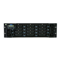
Infortrend EonStor Hardware Manual (216 pages)
Brand:
Infortrend
| Category:
Storage
| Size: 22.26 MB
Table of Contents
Legal Information
2
Contact Information
3
Copyright Notice
4
Safety Precautions
5
About this Manual
8
Table of Contents
10
Introduction
14
Product Overview
14
Model Naming Conventions
14
Model Variations
15
2U Series
16
Series
17
4U Series
19
Major Components
20
RAID Controller and Interface
20
JBOD Controller and Interface
20
Power Supply Unit with Built-In Cooling Module
21
The Rear Panel
22
Dual Controller Models
22
Single-Controller Models
23
Upgrading Single Controller to Dual Controller System
23
Connection between RAID and JBOD
23
Chassis
24
Front Panel
24
Rear Panel
26
Internal Backplane
31
Front Panel Components
32
LCD/LED Panel
32
Chassis Ear
34
Drive Tray
35
Rear Panel Components
36
Controller Module of RAID Models
36
Controller Module of JBOD Models
37
Host Port of RAID Models
38
Fibre-Host RAID Models (Sxxf Series)
38
SAS-Host RAID Models (Sxxs Series)
39
Iscsi-Host RAID Models (Sxxe Series)
40
Cache Backup Module (CBM) for RAID Models
41
2U-Gxxxx Systems & S12S-J1000G PSU
42
DC PSU for Systems with "N" Designation
43
2U Redundant and 3U RAID Systems PSU & Cooling Module
44
4U RAID Systems PSU
45
4U RAID Systems Cooling Module
46
System Monitoring Features
47
Expansion Enclosure Support
47
I 2 C Bus
48
Firmware (FW) and Sanwatch
48
Audible Alarms
48
Hot-Swapping
49
Hardware Installation
50
Installation Prerequisites
50
Installation Procedures Overview
51
Unpacking the System
52
Box Contents
52
Preinstalled Components
52
Components to be Installed
52
Installing Controller Module(S)
53
Installing Hard Drive(S)
54
Hard Drive Installation Prerequisites
54
Mux Board Installation
56
SAS Interface
60
Installing the Hard Drive into Drive Tray
61
Installing the Hard Drive Tray into the Enclosure
62
Installing CBM for RAID Models
63
Removing the RAID Controller
63
Controller Type
64
Installing the BBU (Type I)
64
Installing the FBM (Type I)
65
Installing the BBU (Type II)
66
Installing the RAID Controller
67
Installing the Earth Lead Kit for DC PSU Systems
68
System Connection
70
General Considerations on Making Connections
70
Host-Side Topologies
71
Host-Side Parameters
71
Maximum Concurrent Host LUN Connection ("Nexus" in SCSI)
72
Maximum Queued I/O Count
73
Fibre-Host RAID Connections
74
Fibre-Host Components (Including 10GB Iscsi)
74
Fibre-Host Topologies
76
Fibre Cabling
77
Simple End-To-End Connection
78
DAS (Direct-Attached) Connection
79
Switched Fabric Connection (Dual-Controller)
81
Switched Fabric Connection (Single-Controller)
83
SAS-Host RAID Connections
85
Sxxs-R/G2240-4 Controllers in das (Direct-Attached Storage) Configuration
86
DAS (Direct-Attached Storage) Connection with Redundant Host Path
88
DAS (Direct-Attached Storage) Connection to Two Servers
90
Iscsi-Host RAID Connections
91
Network & Host Connection Topologies
92
High Availability IP SAN with Redundant RAID Controller
93
Single-Controller with Fault-Tolerant Path
95
High Availability IP SAN (Recommended Cabling Method for Remote Replication)
96
High Availability IP SAN with Port Trunk (Remote Replication Enabled)
98
Single-Controller with Trunk
100
Hybrid Host Connections
101
Single Hybrid Unit Connected to FC/ Iscsi Hosts
101
Utilizing Hybrid Iscsi Ports for Data Replication
102
JBOD Connections
103
SAS Expansion Links
104
Type I JBOD SAS Expansion Configuration
104
Type II JBOD SAS Expansion Configuration
107
Configuration Rules
109
Management Console Connections
111
Power Connections
112
Checklist
112
DC Power Supply Power Cord Connection
113
Connecting Power Cords
114
Power on Procedure
116
Power on Status Check
117
LCD Screen
119
Power off Procedure
120
System Monitoring
121
Monitoring Features
121
Front Panel
123
LCD Keypad for RAID Models
123
LCD Panel LED Definitions
124
LED Panel for JBOD Models
125
Drive Tray LED
127
Controller LED
128
Controller LED for RAID Models
128
Controller LED for JBOD Models
130
Ethernet Management Port LED for RAID Models
131
Iscsi Host Port LED
132
Hybrid Iscsi Ports
132
10Gb Iscsi Host Port LED
133
Fibre-Host Port LED for FC RAID Models
134
SAS-Host Port LED for SAS RAID Models
135
PSU / Cooling Module Leds
136
2UL-Gxxxx Model and 4U RAID Power Supply LED
137
2UL-Gxxxx Model RAID System Cooling Module LED
138
4U RAID System Cooling M Odule LED
138
Alarms and I2C Bus
139
Audible Alarms
139
Restoring Default System Settings
140
Restoring Default Settings
140
System Maintenance
142
Replacing the Controller Module(S): Single / Dual / Simultaneous Upgrade
143
Replacing the Memory Module on RAID Systems
147
Replacing the CBM for RAID Models
149
BBU Fault Conditions and Precautions
150
Replacing the BBU
151
Replacing the FBM
152
Replacing the Power Supply Module / Cooling Module
153
Detecting a Failed PSU
153
Replacing the Power Supply Unit
154
Replacing 2UL-Gxxxx Model PSU
156
Replacing 4U RAID System PSU
158
Replacing a Cooling Module
160
Replacing 2UL-Gxxxx RAID System Cooling Module
161
Replacing 4U RAID Systems Cooling Module
162
Replacing a Hard Drive
163
Replacing the Enclosure
166
Differential Diagnosis to Determine Backplane Failure
167
Enclosure Replacement Must Knows
168
Enclosure Replacement Procedure
169
Appendix
171
Technical Specifications
171
Host/Drive Interface
171
RAID Configurations for RAID Models
172
Fault Tolerance for RAID Models
173
Power Supply
174
Dimensions
175
Environment
176
Pin-Out
177
4 / 8 / 16Gbps Fibre Channel and 10Gbps Iscsi Host Port Pin-Out
178
SAS Host Port Pin-Out
180
Gbe Iscsi Host Port Pin-Out
181
DB-9 Serial Port & Cable
182
Ethernet Management Port
183
SAS (SFF-8088) Expansion Port Pin-Out
184
STP Ethernet Cable (Optional Accessory: Fibre-Host RAID Models)
185
Certifications
186
Summary
186
Installing the Earth Lead Kit for DC PSU Systems
188
Slide Rail Kit Installation Guide
191
RAID/JBOD Models and Corresponding Slide Rail Kits
191
Eonstor DS Series
191
Eonstor Series
192
Enclosure Installation Prerequisites
193
Unpacking the System
194
Component Installation Procedure
194
Tools Required
194
IFT-9272Ceslide28-0030 / IFT-9272Ceslide36-0030
195
IFT-9272 Kit Contents
195
Installation Procedure
196
IFT-9273Ceslide32-0010 / IFT-9273Ceslide36-0010
200
IFT-9273 Kit Contents
200
Installation Procedure
201
IFT-9279Cslider36
205
IFT-9279 Kit Contents
205
Installation Procedure
206
IFT-9373Cslider36-0010
208
IFT-9373 Kit Contents
209
Installation Procedure
210
Removing the Enclosure
215
Once Mounted
216
Advertisement
Advertisement
Related Products
Infortrend EonStor DS
Infortrend EonStor CS
Infortrend EonStor GS Series
Infortrend EonStor GSe Series
Infortrend EonStor GSe Pro Series
Infortrend EonStor GSa Series
Infortrend EonStor GSc Series
Infortrend EonStor CS Series
Infortrend EonStor GSi Series
Infortrend EonStor CS G EonStor CS D
Infortrend Categories
Storage
Network Storage Server
Speaker System
Computer Hardware
Measuring Instruments
More Infortrend Manuals
Login
Sign In
OR
Sign in with Facebook
Sign in with Google
Upload manual
Upload from disk
Upload from URL