Sign In
Upload
Manuals
Brands
IEI Technology Manuals
Motherboard
NANO-QM770
IEI Technology NANO-QM770 Manuals
Manuals and User Guides for IEI Technology NANO-QM770. We have
2
IEI Technology NANO-QM770 manuals available for free PDF download: User Manual
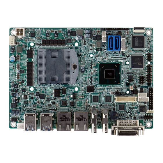
IEI Technology NANO-QM770 User Manual (191 pages)
EPIC SBC with 3rd Generation 22nm Intel Mobile CPU Up to 8.0 GB DDR3, DVI,HDMI, LVDS, Dual GbE, SATA 6Gb/s, USB 3.0, PCle Mini, Intel ATM,RoHS
Brand:
IEI Technology
| Category:
Motherboard
| Size: 8 MB
Table of Contents
User Manual
1
Table of Contents
4
1 Introduction
17
Introduction
18
Benefits
18
Features
18
Figure 1-1: NANO-QM770
18
Connectors
19
Figure 1-2: Connectors (Front)
19
Figure 1-3: Connectors (Solder Side)
20
Dimensions
21
Figure 1-4: Dimensions (MM)
21
Data Flow
22
Figure 1-5: Data Flow Diagram
22
Technical Specifications
23
Table 1-1: Technical Specifications
24
2 Packing List
25
Anti-Static Precautions
26
Unpacking Precautions
26
Packing List
27
Optional Items
28
Table 2-1: Packing List
28
Table 2-2: Optional Items
29
3 Connector Pinouts
30
Peripheral Interface Connectors
31
Layout
31
Figure 3-1: Connector and Jumper Locations
31
Peripheral Interface Connectors
32
Figure 3-2: Connector and Jumper Locations (Solder Side)
32
External Interface Panel Connectors
33
Table 3-1: Peripheral Interface Connectors
33
Table 3-2: Rear Panel Connectors
33
Internal Peripheral Connectors
34
Audio Connector
34
Figure 3-3: Audio Connector Location
34
Table 3-3: Audio Connector Pinouts
34
Battery Connector
35
Figure 3-4: Battery Connector Location
35
Table 3-4: Battery Connector Pinouts
35
Digital I/O Connector
36
Fan Connector (CPU)
36
Figure 3-5: Digital I/O Connector Location
36
Table 3-5: Digital I/O Connector Pinouts
36
Fan Connector (System)
37
Figure 3-6: CPU Fan Connector Location
37
Figure 3-7: System Fan Connector Location
37
Table 3-6: CPU Fan Connector Pinouts
37
Front Panel Connector
38
Figure 3-8: Front Panel Connector Location
38
Table 3-7: System Fan Connector Pinouts
38
Table 3-8: Front Panel Connector Pinouts
38
Keyboard/Mouse Connector
39
LVDS Connector
39
Figure 3-9: Keyboard/Mouse Connector Location
39
Table 3-9: Keyboard/Mouse Connector Pinouts
39
Figure 3-10: LVDS Connector Location
40
Table 3-10: LVDS Connector Pinouts
40
LVDS Backlight Connector
41
Pcie Mini Card Slot
41
Figure 3-11: LVDS Backlight Inverter Connector
41
Table 3-11: Backlight Inverter Connector Pinouts
41
Figure 3-12: Pcie Mini Card Slot Location
42
Power Connector (12V)
43
Figure 3-13: Power Connector Location
43
Table 3-12: Pcie Mini Card Slot Pinouts
43
Table 3-13: Power Connector Pinouts
43
Serial Port Connectors (COM1, COM2)
44
RS-422/485 Serial Port Connector (COM3)
44
Figure 3-14: RS-232 Serial Port Connector Locations
44
Table 3-14: Serial Port Connector Pinouts
44
SATA Drive Connectors
45
Figure 3-15: RS-422/485 Serial Port Connector Location
45
Table 3-15: RS-422/485 Serial Port Connector Pinouts
45
Table 3-16: D-Sub 9 RS-422/485 Pinouts
45
SATA Power Connectors
46
Figure 3-16: SATA Drive Connector Locations
46
Table 3-17: SATA Drive Connector Pinouts
46
Smbus Connector
47
Figure 3-17: SATA Power Connector Locations
47
Figure 3-18: Smbus Connector Location
47
Table 3-18: SATA Power Connector Pinouts
47
SO-DIMM Connector
48
SPI Flash Connector
48
Figure 3-19: SO-DIMM Connector Location
48
Table 3-19: Smbus Connector Pinouts
48
TPM Connector
49
Figure 3-20: SPI Flash Connector Location
49
Table 3-20: SPI Flash Connector Pinouts
49
USB 2.0 Connector
50
Figure 3-21: TPM Connector Location
50
Table 3-21: TPM Connector Pinouts
50
External Interface Connectors
51
DVI Connector
51
Figure 3-22: USB Connector Location
51
Figure 3-23: External Interface Connectors
51
Table 3-22: USB Port Connector Pinouts
51
Ethernet Connectors
52
Figure 3-24: DVI-I Connector
52
Table 3-23: DVI Connector Pinouts
52
HDMI Connectors
53
Figure 3-25: Ethernet Connector
53
Table 3-24: LAN Pinouts
53
Table 3-25: Connector Leds
53
USB 3.0 Connectors
54
Figure 3-26: HDMI Connector
54
Table 3-26: HDMI Connector Pinouts
54
Table 3-27: USB Port Pinouts
55
4 Installation
56
Anti-Static Precautions
57
Installation Considerations
57
So-DIMM Installation
59
Pcie Mini Card Installation
59
Figure 4-1: SO-DIMM Installation
59
Jumper Settings
60
Figure 4-2: Pcie Mini Card Installation
60
AT/ATX Mode Selection
61
Table 4-1: Jumpers
61
Table 4-2: AT/ATX Mode Selection Jumper Settings
61
Clear CMOS
62
Figure 4-3: AT/ATX Mode Selection Jumper Location
62
Clear ME RTC Registers
63
Figure 4-4: Clear CMOS Jumper Location
63
Table 4-3: Clear CMOS Jumper Settings
63
Table 4-4: Clear ME RTC Registers Jumper Settings
63
Figure 4-5: Clear ME RTC Registers Jumper Location
64
Figure 4-6: Flash Descriptor Security Override Jumper Location
64
Flash Descriptor Security Override
64
Table 4-5: Flash Descriptor Security Override Jumper Settings
64
Figure 4-7: LVDS Voltage Selection Jumper Location
65
LVDS Resolution Selection
65
LVDS Voltage Selection
65
Table 4-6: LVDS Voltage Selection Jumper Settings
65
Figure 4-8: LVDS Resolution Selection Jumper Location
66
Pcie Mini/Msata Mode Selection
66
Table 4-7: LVDS Screen Resolution Jumper Settings
66
Chassis Installation
67
Airflow
67
Motherboard Installation
67
Figure 4-9: Pcie Mini/Msata Mode Selection Jumper Location
67
Table 4-8: Pcie Mini/Msata Mode Selection Jumper Settings
67
Internal Peripheral Device Connections
68
AT Power Connection
68
Figure 4-10: Power Cable to Motherboard Connection
68
Audio Kit Installation
69
Figure 4-11: Connect Power Cable to Power Supply
69
SATA Drive Connection
70
Figure 4-12: Audio Kit Cable Connection
70
Single RS-232 Cable (W/O Bracket)
71
Figure 4-13: SATA Drive Cable Connection
71
External Peripheral Interface Connection
72
DVI Display Device Connection
72
Figure 4-14: Single RS-232 Cable Installation
72
HDMI Display Device Connection
73
Figure 4-15: DVI Connector
73
LAN Connection
74
Figure 4-16: HDMI Connection
74
USB Connection
75
Figure 4-17: LAN Connection
75
Intel ® Amt Setup Procedure
76
Figure 4-18: USB Connector
76
5 Bios
78
Introduction
79
Starting Setup
79
Using Setup
79
Getting Help
80
Unable to Reboot after Configuration Changes
80
BIOS Menu Bar
80
Table 5-1: BIOS Navigation Keys
80
Main
81
BIOS Menu 1: Main
81
Advanced
82
BIOS Menu 2: Advanced
82
ACPI Configuration
83
BIOS Menu 3: ACPI Configuration
83
RTC Wake Settings
84
BIOS Menu 4: RTC Wake Settings
84
Trusted Computing
85
BIOS Menu 5: Trusted Computing
85
CPU Configuration
86
BIOS Menu 6: CPU Configuration
86
SATA Configuration
88
BIOS Menu 7: SATA Configuration
88
Intel(R) Rapid Start Technology
89
Intel TXT(LT) Configuration
89
BIOS Menu 8: Intel(R) Rapid Start Technology
89
AMT Configuration
90
BIOS Menu 9: Intel TXT(LT) Configuration
90
BIOS Menu 10: AMT Configuration
90
USB Configuration
91
BIOS Menu 11: USB Configuration
91
F81866 Super IO Configuration
92
BIOS Menu 12: Super IO Configuration
92
Serial Port N Configuration
93
BIOS Menu 13: Serial Port N Configuration Menu
93
F81866 H/W Monitor
96
BIOS Menu 14: Hardware Health Configuration
96
Smart Fan Mode Configuration
97
BIOS Menu 15: FAN 1 Configuration
97
Serial Port Console Redirection
98
BIOS Menu 16: Serial Port Console Redirection
98
IEI Feature
99
BIOS Menu 17: IEI Feature
99
Chipset
100
BIOS Menu 18: Chipset
100
PCH-IO Configuration
101
BIOS Menu 19:PCH-IO Configuration
101
System Agent (SA) Configuration
102
Graphics Configuration
103
BIOS Menu 20: System Agent (SA) Configuration
103
BIOS Menu 21: Graphics Configuration
104
Memory Configuration
106
Boot
107
BIOS Menu 22: Memory Configuration
107
BIOS Menu 23: Boot
107
Security
110
Exit
110
BIOS Menu 24: Security
110
BIOS Menu 25:Exit
111
6 Software Drivers
112
Available Software Drivers
113
Software Installation
113
Figure 6-1: Introduction Screen
114
Figure 6-2: Available Drivers
114
Chipset Driver Installation
115
Figure 6-3: Chipset Driver Welcome Screen
115
Figure 6-4: Chipset Driver License Agreement
116
Figure 6-5: Chipset Driver Read Me File
116
Figure 6-6: Chipset Driver Setup Operations
117
Graphics Driver Installation
118
Figure 6-7: Chipset Driver Installation Finish Screen
118
Figure 6-8: Graphics Driver Welcome Screen
119
Figure 6-9: Graphics Driver License Agreement
119
Figure 6-10: Graphics Driver Setup Operations
120
Figure 6-11: Graphics Driver Installation Finish Screen
120
Lan Driver Installation
121
Figure 6-12: Windows Control Panel
121
Figure 6-13: System Control Panel
121
Figure 6-14: Device Manager List
122
Figure 6-15: Update Driver Software Window
123
Figure 6-16: Locate Driver Files
123
Audio Driver Installation
124
Figure 6-17: LAN Driver Installation
124
Figure 6-18: LAN Driver Installation Complete
124
Figure 6-19: Installshield Wizard Welcome Screen
125
Figure 6-20: Audio Driver Software Configuration
126
Figure 6-21: Restart the Computer
126
Intel® Rapid Storage Technology Driver Installation
127
Figure 6-22: SATA RAID Driver Welcome Screen
127
Figure 6-23: SATA RAID Driver License Agreement
128
Figure 6-24: SATA RAID Driver Read Me File
128
Figure 6-25: SATA RAID Driver Setup Operations
129
Figure 6-26: SATA RAID Driver Installation Finish Screen
129
Usb 3.0 Driver Installation
130
Figure 6-27: USB 3.0 Driver Welcome Screen
130
Figure 6-28: USB 3.0 Driver License Agreement
131
Figure 6-29: USB 3.0 Driver Read Me File
131
Figure 6-30: USB 3.0 Driver Setup Operations
132
Figure 6-31: USB 3.0 Driver Installation Finish Screen
132
Intel® AMT Driver Installation
133
Figure 6-32: Intel® ME Driver Welcome Screen
134
Figure 6-33: Intel® ME Driver License Agreement
134
Figure 6-34: Intel® ME Driver Setup Operations
135
Figure 6-35: Intel® ME Driver Installation Finish Screen
135
ABIOS Options
136
B One Key Recovery
139
One Key Recovery Introduction
140
Figure B-1: IEI One Key Recovery Tool Menu
140
System Requirement
141
Supported Operating System
142
Setup Procedure for Windows
143
Hardware and BIOS Setup
144
Create Partitions
144
Figure B-2: Launching the Recovery Tool
145
Figure B-3: Recovery Tool Setup Menu
145
Figure B-4: Command Prompt
146
Figure B-5: Partition Creation Commands
147
Install Operating System, Drivers and Applications
148
Building the Recovery Partition
149
Figure B-6: Launching the Recovery Tool
149
Figure B-7: Manual Recovery Environment for Windows
149
Figure B-8: Building the Recovery Partition
150
Figure B-9: Press any Key to Continue
150
Create Factory Default Image
151
Figure B-10: Press F3 to Boot into Recovery Mode
151
Figure B-11: Recovery Tool Menu
151
Figure B-12: about Symantec Ghost Window
152
Figure B-13: Symantec Ghost Path
152
Figure B-14: Select a Local Source Drive
153
Figure B-15: Select a Source Partition from Basic Drive
153
Figure B-16: File Name to Copy Image to
154
Figure B-17: Compress Image
154
Figure B-18: Image Creation Confirmation
155
Figure B-19: Creating Image
155
Figure B-20: Image Creation Complete
155
Auto Recovery Setup Procedure
156
Figure B-21: Press any Key to Continue
156
Figure B-22: Auto Recovery Utility
157
Figure B-23: Disable Automatically Restart
157
Figure B-24: Launching the Recovery Tool
158
Figure B-25: Auto Recovery Environment for Windows
158
Figure B-26: Building the Auto Recovery Partition
159
Figure B-27: Factory Default Image Confirmation
159
Figure B-28: Creating Image
160
Figure B-29: Press any Key to Continue
160
Setup Procedure for Linux
161
Figure B-30: IEI Feature BIOS Menu
161
Figure B-31: Partitions for Linux
162
Figure B-32: Manual Recovery Environment for Linux
163
Figure B-33: Access Menu.lst in Linux (Text Mode)
163
Recovery Tool Functions
164
Figure B-34: Recovery Tool Menu
164
Figure B-35: Recovery Tool Main Menu
165
Factory Restore
166
Figure B-36: Restore Factory Default
166
Figure B-37: Recovery Complete Window
166
Backup System
167
Figure B-38: Backup System
167
Figure B-39: System Backup Complete Window
167
Figure B-40: Restore Backup
168
Figure B-41: Restore System Backup Complete Window
168
Restore Your Last Backup
168
Figure B-42: Symantec Ghost Window
169
Manual
169
Restore Systems from a Linux Server through Lan
170
B.6 R Estore S Ystems from a L Inux S Erver through Lan
170
Configure DHCP Server Settings
171
Configure TFTP Settings
172
Configure One Key Recovery Server Settings
173
Create Shared Directory
174
Start the DHCP, TFTP and HTTP
174
Setup a Client System for Auto Recovery
175
Figure B-43: Disable Automatically Restart
176
Other Information
178
Using AHCI Mode or Ali M5283 / VIA VT6421A Controller
178
B.7 O Ther I Nformation
178
System Memory Requirement
180
C Terminology
181
D Digital I/O Interface
185
Introduction
186
Dio Connector Pinouts
186
Assembly Language Samples
186
Enable the DIO Input Function
186
Table 6-1: Digital I/O Connector Pinouts
186
D.1 I Ntroduction
186
Enable the DIO Output Function
187
E Hazardous Materials Disclosure
188
Hazardous Materials Disclosure Table for IPB Products Certified as Rohs Compliant under 2002/95/EC Without Mercury
189
E.1 H Azardous M Aterials D Isclosure T Able for Ipb P Roducts C Ertified as R O Hs C Ompliant U Nder 2002/95/Ec W Ithout M Ercury
189
Advertisement
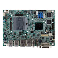
IEI Technology NANO-QM770 User Manual (145 pages)
Brand:
IEI Technology
| Category:
Single board computers
| Size: 6 MB
Table of Contents
Table of Contents
5
Introduction
15
Introduction
16
Benefits
16
Features
16
Figure 1-1: NANO-QM770
16
Connectors
17
Figure 1-2: Connectors (Front)
17
Figure 1-3: Connectors (Solder Side)
18
Dimensions
19
Figure 1-4: Dimensions (MM)
19
Data Flow
20
Figure 1-5: Data Flow Diagram
20
Technical Specifications
21
Table 1-1: Technical Specifications
22
Packing List
23
Anti-Static Precautions
24
Unpacking Precautions
24
Packing List
25
Optional Items
26
Table 2-1: Packing List
26
Table 2-2: Optional Items
27
Connector Pinouts
28
Peripheral Interface Connectors
29
Layout
29
Figure 3-1: Connector and Jumper Locations
29
Peripheral Interface Connectors
30
Figure 3-2: Connector and Jumper Locations (Solder Side)
30
External Interface Panel Connectors
31
Table 3-1: Peripheral Interface Connectors
31
Table 3-2: Rear Panel Connectors
31
Internal Peripheral Connectors
32
Audio Connector
32
Figure 3-3: Audio Connector Location
32
Table 3-3: Audio Connector Pinouts
32
Battery Connector
33
Figure 3-4: Battery Connector Location
33
Table 3-4: Battery Connector Pinouts
33
Digital I/O Connector
34
Fan Connector (CPU)
34
Figure 3-5: Digital I/O Connector Location
34
Table 3-5: Digital I/O Connector Pinouts
34
Fan Connector (System)
35
Figure 3-6: CPU Fan Connector Location
35
Figure 3-7: System Fan Connector Location
35
Table 3-6: CPU Fan Connector Pinouts
35
Front Panel Connector
36
Figure 3-8: Front Panel Connector Location
36
Table 3-7: System Fan Connector Pinouts
36
Table 3-8: Front Panel Connector Pinouts
36
Keyboard/Mouse Connector
37
LVDS Connector
37
Figure 3-9: Keyboard/Mouse Connector Location
37
Table 3-9: Keyboard/Mouse Connector Pinouts
37
Figure 3-10: LVDS Connector Location
38
Table 3-10: LVDS Connector Pinouts
38
LVDS Backlight Connector
39
Pcie Mini Card Slot
39
Figure 3-11: LVDS Backlight Inverter Connector
39
Table 3-11: Backlight Inverter Connector Pinouts
39
Figure 3-12: Pcie Mini Card Slot Location
40
Power Connector (12V)
41
Figure 3-13: Power Connector Location
41
Table 3-12: Pcie Mini Card Slot Pinouts
41
Table 3-13: Power Connector Pinouts
41
Serial Port Connectors (COM1, COM2)
42
RS-422/485 Serial Port Connector (COM3)
42
Figure 3-14: RS-232 Serial Port Connector Locations
42
Table 3-14: Serial Port Connector Pinouts
42
SATA Drive Connectors
43
Figure 3-15: RS-422/485 Serial Port Connector Location
43
Table 3-15: RS-422/485 Serial Port Connector Pinouts
43
Table 3-16: D-Sub 9 RS-422/485 Pinouts
43
SATA Power Connectors
44
Figure 3-16: SATA Drive Connector Locations
44
Table 3-17: SATA Drive Connector Pinouts
44
Smbus Connector
45
Figure 3-17: SATA Power Connector Locations
45
Figure 3-18: Smbus Connector Location
45
Table 3-18: SATA Power Connector Pinouts
45
SO-DIMM Connector
46
SPI Flash Connector
46
Figure 3-19: SO-DIMM Connector Location
46
Table 3-19: Smbus Connector Pinouts
46
TPM Connector
47
Figure 3-20: SPI Flash Connector Location
47
Table 3-20: SPI Flash Connector Pinouts
47
USB 2.0 Connector
48
Figure 3-21: TPM Connector Location
48
Table 3-21: TPM Connector Pinouts
48
External Interface Connectors
49
DVI Connector
49
Figure 3-22: USB Connector Location
49
Figure 3-23: External Interface Connectors
49
Table 3-22: USB Port Connector Pinouts
49
Ethernet Connectors
50
Figure 3-24: DVI-I Connector
50
Table 3-23: DVI Connector Pinouts
50
HDMI Connectors
51
Figure 3-25: Ethernet Connector
51
Table 3-24: LAN Pinouts
51
Table 3-25: Connector Leds
51
USB 3.0 Connectors
52
Figure 3-26: HDMI Connector
52
Table 3-26: HDMI Connector Pinouts
52
Table 3-27: USB Port Pinouts
53
Installation
54
Anti-Static Precautions
55
Installation Considerations
55
So-DIMM Installation
57
Pcie Mini Card Installation
57
Figure 4-1: SO-DIMM Installation
57
Jumper Settings
58
Figure 4-2: Pcie Mini Card Installation
58
AT/ATX Mode Selection
59
Table 4-1: Jumpers
59
Table 4-2: AT/ATX Mode Selection Jumper Settings
59
Clear CMOS
60
Figure 4-3: AT/ATX Mode Selection Jumper Location
60
Clear ME RTC Registers
61
Figure 4-4: Clear CMOS Jumper Location
61
Table 4-3: Clear CMOS Jumper Settings
61
Table 4-4: Clear ME RTC Registers Jumper Settings
61
Flash Descriptor Security Override
62
Figure 4-5: Clear ME RTC Registers Jumper Location
62
Figure 4-6: Flash Descriptor Security Override Jumper Location
62
Table 4-5: Flash Descriptor Security Override Jumper Settings
62
LVDS Voltage Selection
63
LVDS Resolution Selection
63
Figure 4-7: LVDS Voltage Selection Jumper Location
63
Table 4-6: LVDS Voltage Selection Jumper Settings
63
Pcie Mini/Msata Mode Selection
64
Figure 4-8: LVDS Resolution Selection Jumper Location
64
Table 4-7: LVDS Screen Resolution Jumper Settings
64
Chassis Installation
65
Airflow
65
Motherboard Installation
65
Figure 4-9: Pcie Mini/Msata Mode Selection Jumper Location
65
Table 4-8: Pcie Mini/Msata Mode Selection Jumper Settings
65
Internal Peripheral Device Connections
66
AT Power Connection
66
Figure 4-10: Power Cable to Motherboard Connection
66
Audio Kit Installation
67
Figure 4-11: Connect Power Cable to Power Supply
67
SATA Drive Connection
68
Figure 4-12: Audio Kit Cable Connection
68
Single RS-232 Cable (W/O Bracket)
69
Figure 4-13: SATA Drive Cable Connection
69
Intel ® Amt Setup Procedure
70
Figure 4-14: Single RS-232 Cable Installation
70
Bios
72
Introduction
73
Starting Setup
73
Using Setup
73
Getting Help
74
Unable to Reboot after Configuration Changes
74
BIOS Menu Bar
74
Table 5-1: BIOS Navigation Keys
74
Main
75
BIOS Menu 1: Main
75
Advanced
76
BIOS Menu 2: Advanced
76
ACPI Configuration
77
BIOS Menu 3: ACPI Configuration
77
RTC Wake Settings
78
BIOS Menu 4: RTC Wake Settings
78
Trusted Computing
79
BIOS Menu 5: Trusted Computing
79
CPU Configuration
80
BIOS Menu 6: CPU Configuration
80
SATA Configuration
82
BIOS Menu 7: SATA Configuration
82
Intel(R) Rapid Start Technology
83
Intel TXT(LT) Configuration
83
BIOS Menu 8: Intel(R) Rapid Start Technology
83
AMT Configuration
84
BIOS Menu 9: Intel TXT(LT) Configuration
84
BIOS Menu 10: AMT Configuration
84
USB Configuration
85
BIOS Menu 11: USB Configuration
85
F81866 Super IO Configuration
86
BIOS Menu 12: Super IO Configuration
86
Serial Port N Configuration
87
BIOS Menu 13: Serial Port N Configuration Menu
87
F81866 H/W Monitor
90
BIOS Menu 14: Hardware Health Configuration
90
Smart Fan Mode Configuration
91
BIOS Menu 15: FAN 1 Configuration
91
Serial Port Console Redirection
92
BIOS Menu 16: Serial Port Console Redirection
92
IEI Feature
93
BIOS Menu 17: IEI Feature
93
Chipset
94
BIOS Menu 18: Chipset
94
PCH-IO Configuration
95
BIOS Menu 19:PCH-IO Configuration
95
System Agent (SA) Configuration
96
Graphics Configuration
97
BIOS Menu 20: System Agent (SA) Configuration
97
BIOS Menu 21: Graphics Configuration
98
Memory Configuration
100
Boot
101
BIOS Menu 22: Memory Configuration
101
BIOS Menu 23: Boot
101
Security
104
Exit
104
BIOS Menu 24: Security
104
BIOS Menu 25:Exit
105
Software Drivers
106
Available Software Drivers
107
Software Installation
107
Figure 6-1: Introduction Screen
108
Figure 6-2: Available Drivers
108
Chipset Driver Installation
109
Figure 6-3: Chipset Driver Welcome Screen
109
Figure 6-4: Chipset Driver License Agreement
110
Figure 6-5: Chipset Driver Read Me File
110
Figure 6-6: Chipset Driver Setup Operations
111
Graphics Driver Installation
112
Figure 6-7: Chipset Driver Installation Finish Screen
112
Figure 6-8: Graphics Driver Welcome Screen
113
Figure 6-9: Graphics Driver License Agreement
113
Figure 6-10: Graphics Driver Setup Operations
114
Figure 6-11: Graphics Driver Installation Finish Screen
114
Lan Driver Installation
115
Figure 6-12: Windows Control Panel
115
Figure 6-13: System Control Panel
115
Figure 6-14: Device Manager List
116
Figure 6-15: Update Driver Software Window
117
Figure 6-16: Locate Driver Files
117
Audio Driver Installation
118
Figure 6-17: LAN Driver Installation
118
Figure 6-18: LAN Driver Installation Complete
118
Figure 6-19: Installshield Wizard Welcome Screen
119
Figure 6-20: Audio Driver Software Configuration
120
Figure 6-21: Restart the Computer
120
Intel® Rapid Storage Technology Driver Installation
121
Figure 6-22: SATA RAID Driver Welcome Screen
121
Figure 6-23: SATA RAID Driver License Agreement
122
Figure 6-24: SATA RAID Driver Read Me File
122
Figure 6-25: SATA RAID Driver Setup Operations
123
Figure 6-26: SATA RAID Driver Installation Finish Screen
123
Usb 3.0 Driver Installation
124
Figure 6-27: USB 3.0 Driver Welcome Screen
124
Figure 6-28: USB 3.0 Driver License Agreement
125
Figure 6-29: USB 3.0 Driver Read Me File
125
Figure 6-30: USB 3.0 Driver Setup Operations
126
Figure 6-31: USB 3.0 Driver Installation Finish Screen
126
Intel® AMT Driver Installation
127
Figure 6-32: Intel® ME Driver Welcome Screen
128
Figure 6-33: Intel® ME Driver License Agreement
128
Figure 6-34: Intel® ME Driver Setup Operations
129
Figure 6-35: Intel® ME Driver Installation Finish Screen
129
A Regulatory Compliance
130
BBIOS Options
132
C Terminology
135
D Digital I/O Interface
139
Introduction
140
Assembly Language Sample 1
141
Assembly Language Sample 2
141
E Hazardous Materials Disclosure
142
Hazardous Materials Disclosure Table for IPB Products Certified as Rohs Compliant under 2002/95/EC Without Mercury
143
Advertisement
Related Products
IEI Technology NANO-QM871
IEI Technology NANO-QM57A
IEI Technology NANO-QM871-i1
IEI Technology NANO-QM871-i1-i7
IEI Technology NANO-QM871-i1-i5
IEI Technology NANO-QM871-i1-i3
IEI Technology NANO-QM871-i1-C
IEI Technology NANO-QM871-i1-C-R11
IEI Technology NANO-QM871-I1-C-R10
IEI Technology NANO-QM871-I1-I7-R11
IEI Technology Categories
Motherboard
Touch Panel
Computer Hardware
Single board computers
Desktop
More IEI Technology Manuals
Login
Sign In
OR
Sign in with Facebook
Sign in with Google
Upload manual
Upload from disk
Upload from URL