Sign In
Upload
Manuals
Brands
IEI Technology Manuals
Motherboard
KINO-DBT Series
IEI Technology KINO-DBT Series Manuals
Manuals and User Guides for IEI Technology KINO-DBT Series. We have
2
IEI Technology KINO-DBT Series manuals available for free PDF download: User Manual, Quick Installation Manual
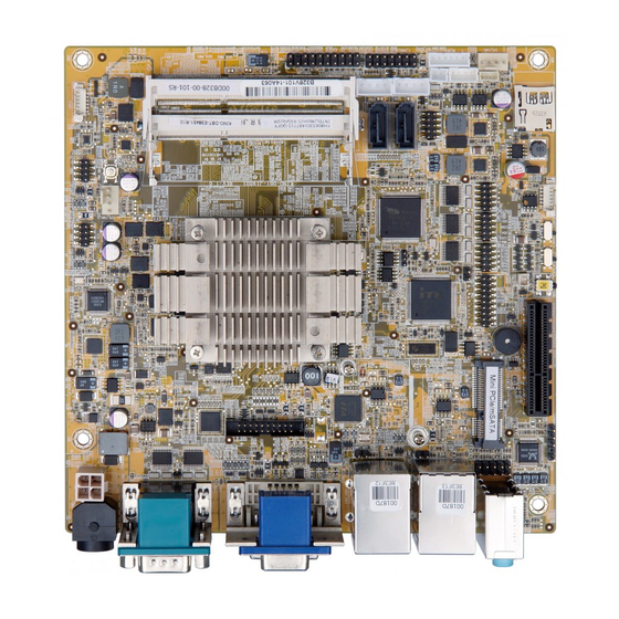
IEI Technology KINO-DBT Series User Manual (133 pages)
Mini-ITX SBC with 22nm Intel Atom or Celeron SoC, Dual GbE, DDR3, DVI, VGA, DisplayPort, USB 3.0, RS-232, RS-422, RS-485, SATA 3G/s. and RoHS
Brand:
IEI Technology
| Category:
Motherboard
| Size: 7 MB
Table of Contents
User Manual
1
Table of Contents
4
1 Introduction
13
Introduction
14
Figure 1-1: KINO-DBT Series
14
Model Variations
15
Table 1-1: Model Variations
15
Benefits
16
Features
16
Connectors
17
Figure 1-2: Connectors
17
Dimensions
18
Figure 1-3: KINO-DBT Series Main Dimensions (MM)
18
Data Flow
19
Figure 1-4: Data Flow Diagram
19
Technical Specifications
20
Table 1-2: KINO-DBT Series Specifications
22
2 Packing List
23
Anti-Static Precautions
24
Unpacking Precautions
24
Packing List
25
Table 2-1: Packing List
25
Optional Items
26
3 Connectors
28
Peripheral Interface Connectors
29
KINO-DBT Layout
29
Figure 3-1: Connectors and Jumpers (Front Side)
29
Peripheral Interface Connectors
30
External Interface Panel Connectors
31
Internal Peripheral Connectors
31
Audio Connector
31
Table 3-1: Peripheral Interface Connectors
31
Table 3-2: Rear Panel Connectors
31
Battery Connector
32
Figure 3-2: Audio Connector Location
32
Table 3-3: Audio Connector Pinouts
32
Chassis Intrusion Connector
33
Figure 3-3: Battery Connector Location
33
Table 3-4: Battery Connector Pinouts
33
Digital I/O Connector
34
Figure 3-4: Chassis Intrusion Connector Location
34
Figure 3-5: Digital I/O Connector Location
34
Table 3-5: Chassis Intrusion Connector Pinouts
34
Displayport Connector
35
Figure 3-6: Displayport Connector Location
35
Table 3-6: Digital I/O Connector Pinouts
35
EC Debug Connector
36
Figure 3-7: EC Debug Connector Location
36
Table 3-7: Displayport Connector Pinouts
36
Fan Connector (CPU)
37
Figure 3-8: CPU Fan Connector Location
37
Table 3-8: EC Debug Connector Pinouts
37
Table 3-9: CPU Fan Connector Pinouts
37
Fan Connector (System)
38
Front Panel Connector
38
Figure 3-9: System Fan Connector Location
38
Table 3-10: System Fan Connector Pinouts
38
Keyboard and Mouse Connector
39
Figure 3-10: Front Panel Connector Location
39
Table 3-11: Front Panel Connector Pinouts
39
LAN LED Connectors
40
Figure 3-11: Keyboard and Mouse Connector Location
40
Table 3-12: Keyboard and Mouse Connector Pinouts
40
Memory Card Slots
41
Figure 3-12: LAN LED Connector Locations
41
Table 3-13: LAN1 LED Connector Pinouts
41
Table 3-14: LAN2 LED Connector Pinouts
41
Pcie X4 Slot
42
Pcie Mini Card Slot
42
Figure 3-13: Memory Card Slot Locations
42
Figure 3-14: Pcie X4 Slot Location
42
Figure 3-15: Pcie Mini Card Slot Location
43
Power Button
44
Figure 3-16: Power Button Location
44
Table 3-15: Pcie Mini Card Slot Pinouts
44
Power Connector
45
Reset Button Connector
45
Figure 3-17: Power Connector Location
45
Table 3-16: Power Connector Pinouts
45
SATA 3Gb/S Drive Connectors
46
Figure 3-18: Reset Button Connector Location
46
Table 3-17: Reset Button Connector Pinouts
46
SATA Power Connectors
47
Figure 3-19: SATA 3Gb/S Drive Connector Locations
47
Table 3-18: SATA 3Gb/S Drive Connector Pinouts
47
Serial Port Connectors, RS-232
48
Figure 3-20: SATA Power Connector Locations
48
Table 3-19: SATA Power Connector Pinouts
48
Serial Port Connector, RS-422/485
49
Figure 3-21: RS-232 Serial Port Connector Locations
49
Table 3-20: RS-232 Serial Port Connector Pinouts
49
Smbus Connector
50
Figure 3-22: RS-422/485 Connector Location
50
Table 3-21: RS-422/485 Connector Pinouts
50
Table 3-22: RS-422/485 Pinouts of D-Sub 9 Connector
50
SPDIF Connector
51
Figure 3-23: Smbus Connector Location
51
Table 3-23: Smbus Connector Pinouts
51
SPI Flash Connector
52
Figure 3-24: SPDIF Connector Location
52
Table 3-24: SPDIF Connector Pinouts
52
SPI Flash Connector, EC
53
Figure 3-25: SPI Flash Connector Location
53
Table 3-25: SPI Flash Connector Pinouts
53
TPM Connector
54
Figure 3-26: SPI EC Flash Connector Location
54
Table 3-26: SPI EC Flash Connector Pinouts
54
USB 2.0 Connectors
55
Figure 3-27: TPM Connector Location
55
Table 3-27: TPM Connector Pinouts
55
Figure 3-28: USB 2.0 Connector Locations
56
Table 3-28: USB1 Pinouts
56
Table 3-29: USB2 Pinouts
56
External Peripheral Interface Connector Panel
57
Audio Connector
57
Figure 3-29: External Peripheral Interface Connector
57
DVI Connector
58
Figure 3-30: Audio Connector
58
Ethernet and USB 2.0 Combo Connector
59
Figure 3-31: DVI-I Connector
59
Figure 3-32: Ethernet Connector
59
Table 3-30: DVI Connector Pinouts
59
Table 3-31: LAN2 Ethernet Connector Pinouts
59
Ethernet and USB 3.0 Combo Connector
60
Table 3-32: Connector Leds
60
Table 3-33: USB 2.0 Port Pinouts
60
Table 3-34: LAN1 Ethernet Connector Pinouts
60
Serial Port Connectors (COM1 and COM2)
61
Figure 3-33: Ethernet Connector
61
Table 3-35: Connector Leds
61
Table 3-36: USB 3.0 Port Pinouts
61
VGA Connector
62
Figure 3-34: Serial Port Pinouts
62
Table 3-37: Serial Port Pinouts
62
Figure 3-35: VGA Connector
63
Table 3-38: VGA Connector Pinouts
63
4 Installation
64
Anti-Static Precautions
65
Installation Considerations
65
SO-DIMM Installation
67
Pcie Mini Card Installation
67
Figure 4-1: SO-DIMM Installation
67
Figure 4-2: Pcie Mini Card Retention Screw Removal
68
Figure 4-3: Pcie Mini Card Installation (Full-Size)
68
System Configuration
69
AT/ATX Power Mode Setting
69
Clear CMOS Button
69
Figure 4-4: AT/ATX Power Mode Switch Location
69
Figure 4-5: Clear CMOS Button Location
69
Flash Descriptor Security Override
70
Msata/Sata Selection
70
Figure 4-6: Flash Descriptor Security Override Jumper Location
70
Table 4-1: Flash Descriptor Security Override Jumper Settings
70
Table 4-2: Msata/Sata Switch Settings
70
USB Power Select
71
Internal Peripheral Device Connections
71
SATA Drive Connection
71
Figure 4-7: Msata/Sata Switch Location
71
Table 4-3: BIOS Options and Configured USB Ports
71
USB Cable Connection
72
Figure 4-8: SATA Drive Cable Connection
72
Figure 4-9: Dual USB Cable Connection
73
5 Bios
74
Introduction
75
Starting Setup
75
Using Setup
75
Getting Help
76
Unable to Reboot after Configuration Changes
76
BIOS Menu Bar
76
Table 5-1: BIOS Navigation Keys
76
Main
77
BIOS Menu 1: Main
77
Advanced
79
ACPI Settings
79
BIOS Menu 2: Advanced
79
BIOS Menu 3: ACPI Configuration
80
Super IO Configuration
81
Serial Port N Configuration
81
BIOS Menu 4: Super IO Configuration
81
BIOS Menu 5: Serial Port N Configuration Menu
81
Iwdd Hardware Monitor
89
BIOS Menu 6: Iwdd Hardware Monitor
90
Smart Fan Mode Configuration
91
BIOS Menu 7: Smart Fan Function
91
RTC Wake Settings
93
BIOS Menu 8: RTC Wake Settings
93
Serial Port Console Redirection
94
BIOS Menu 9: Serial Port Console Redirection
94
CPU Configuration
96
BIOS Menu 10: CPU Configuration
97
IDE Configuration
99
BIOS Menu 11: IDE Configuration
99
Trusted Computing
100
BIOS Menu 12: Trusted Computing
100
USB Configuration
101
BIOS Menu 13: USB Configuration
101
Chipset
102
BIOS Menu 14: Chipset
102
North Bridge
103
Intel IGD Configuration
103
BIOS Menu 15: North Bridge
103
BIOS Menu 16: Intel IGD Configuration
103
South Bridge
105
BIOS Menu 17: South Bridge
105
Table 5-2: BIOS Options and Configured USB Ports
106
Azalia HD Audio
107
BIOS Menu 18: Azalia HD Audio
107
PCI Express Configuration
108
BIOS Menu 19: PCI Express Configuration
108
Security
109
BIOS Menu 20: Security
109
Boot
110
BIOS Menu 21: Boot
110
Exit
112
BIOS Menu 22:Exit
112
6 Software Drivers
114
Available Software Drivers
115
Software Installation
115
Figure 6-1: Available Drivers
116
ABIOS Options
117
B Terminology
120
C Digital I/O Interface
124
Introduction
125
Assembly Language Sample 1
126
Assembly Language Sample 2
126
D Watchdog Timer
127
E Hazardous Materials Disclosure
130
Hazardous Materials Disclosure Table for IPB Products Certified as Rohs Compliant under 2002/95/EC Without Mercury
131
Advertisement
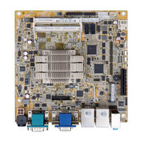
IEI Technology KINO-DBT Series Quick Installation Manual (17 pages)
Mini-ITX SBC with Intel 22nm Atom SoC processors, VGA / DVI-D / iDP, USB 3.0, SATA, HD Audio, RoHS
Brand:
IEI Technology
| Category:
Single board computers
| Size: 0 MB
Advertisement
Related Products
IEI Technology KINO-DH810
IEI Technology KINO-DH610
IEI Technology KINO-DCM236
IEI Technology KINO-DQM170-I7-R11
IEI Technology KINO-DQM170-I5-R11
IEI Technology KINO-DQM170-CE-R10
IEI Technology KINO-DQM170-i7-R10
IEI Technology KINO-DQM170-i3E-R10
IEI Technology KINO-DQM170-I3E-R11
IEI Technology KINO-DH110
IEI Technology Categories
Motherboard
Touch Panel
Computer Hardware
Single board computers
Desktop
More IEI Technology Manuals
Login
Sign In
OR
Sign in with Facebook
Sign in with Google
Upload manual
Upload from disk
Upload from URL