Sign In
Upload
Manuals
Brands
IEI Technology Manuals
Motherboard
KINO-DH610
IEI Technology KINO-DH610 Manuals
Manuals and User Guides for IEI Technology KINO-DH610. We have
1
IEI Technology KINO-DH610 manual available for free PDF download: User Manual
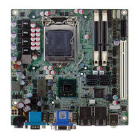
IEI Technology KINO-DH610 User Manual (162 pages)
Mini-ITX SBC Supports LGA1155 for Intel Core i3/ Pentium/Celeron CPU, DDR3, VGA/DVI-D/HDMI, Dual PCIe GbE, Ten USB 2.0, Four SATA 3Gb/s, HD Audio and RoHS
Brand:
IEI Technology
| Category:
Motherboard
| Size: 8 MB
Table of Contents
User Manual
1
Table of Contents
4
1 Introduction
13
Introduction
14
Connectors
14
Figure 1-1: KINO-DH610
14
Figure 1-2: Connectors
15
Dimensions
16
Figure 1-3: KINO-DH610 Dimensions (MM)
16
Data Flow
17
Figure 1-4: Data Flow Diagram
17
Technical Specifications
18
Table 1-1: Technical Specifications
20
2 Unpacking
21
Anti-Static Precautions
22
Unpacking Precautions
22
Packing List
23
Optional Items
24
3 Connectors
26
Peripheral Interface Connectors
27
KINO-DH610 Layout
27
Figure 3-1: Connector and Jumper Locations
27
Peripheral Interface Connectors
28
Table 3-1: Peripheral Interface Connectors
28
External Interface Panel Connectors
29
Internal Peripheral Connectors
29
Battery Connector
29
Table 3-2: Rear Panel Connectors
29
BIOS Update Connector
30
Figure 3-2: Battery Connector Location
30
Table 3-3: Battery Connector Pinouts
30
DDR3 SO-DIMM Slots
31
Figure 3-3: BIOS Update Connector Location
31
Table 3-4: BIOS Update Connector Pinouts
31
Debug Port Connector
32
Figure 3-4: DDR3 SO-DIMM Slot Locations
32
Figure 3-5: Debug Port Connector Location
32
Digital I/O Connector
33
Figure 3-6: Digital I/O Connector Location
33
Table 3-5: Debug Port Connector Pinouts
33
EC Update Connector
34
Figure 3-7: EC Update Connector Location
34
Table 3-6: Digital I/O Connector Pinouts
34
Fan Connector (CPU)
35
Figure 3-8: CPU Fan Connector Locations
35
Table 3-7: EC Update Connector Pinouts
35
Table 3-8: CPU Fan Connector Pinouts
35
Fan Connector (PCH)
36
Front Panel Connector
36
Figure 3-9: PCH Fan Connector Location
36
Table 3-9: PCH Fan Connector Pinouts
36
Keyboard/Mouse Connector
37
Figure 3-10: Front Panel Connector Location
37
Table 3-10: Front Panel Connector Pinouts
37
PCI Slot
38
Figure 3-11: Keyboard/Mouse Connector Location
38
Table 3-11: Keyboard/Mouse Connector Pinouts
38
Pcie X1 Slot
39
Figure 3-12: PCI Slot Location
39
Figure 3-13: Pcie X1 Slot Location
39
Power Connector
40
SATA Drive Connectors
40
Figure 3-14: Power Connector Location
40
Table 3-12: Power Connector Pinouts
40
SATA Power Connectors
41
Figure 3-15: SATA Drive Connector Locations
41
Figure 3-16: SATA Power Connector Locations
41
Serial Port Connector (RS-232/422/485)
42
Figure 3-17: RS-232/422/485 Serial Port Connector Location(Rs-232+RS422/485
42
Table 3-13: SATA Power Connector Pinouts
42
TPM Connector
43
Figure 3-18: TPM Connector Location
43
Table 3-14: RS-232/422/485 Serial Port Connector Pinouts(Rs-232+RS422/485
43
USB Connectors
44
Figure 3-19: USB Connector Locations
44
Table 3-15: TPM Connector Pinouts
44
External Peripheral Interface Connector Panel
45
Figure 3-20: KINO-DH610 External Peripheral Interface Connector
45
Table 3-16: USB Connector Pinouts
45
Audio Connector
46
Ethernet and USB Connector
46
Figure 3-21: Audio Connector
46
Figure 3-22: LAN Connector
47
HDMI Connector
47
Table 3-17: LAN and USB Connector Pinouts
47
Figure 3-23: Power Connector
48
Power Connector
48
Table 3-18: HDMI Connector Pinouts
48
Figure 3-24: RS-232 Serial Port Connector
49
Serial Port
49
Table 3-19: Power Connector Pinouts
49
Table 3-20: RS-232 Serial Port Connector Pinouts
49
Figure 3-25: VGA Connector
50
Table 3-21: DVI and VGA Connector Pinouts
50
VGA and DVI Connector
50
4 Installation
51
Anti-Static Precautions
52
Installation Considerations
53
Basic Installation
54
Socket LGA1155 CPU Installation
54
Figure 4-1: Disengage the CPU Socket Load Lever
55
Figure 4-2: Remove Protective Cover
55
Figure 4-3: Insert the Socket LGA1155 CPU
56
Cooling Kit Installation
57
Figure 4-4: Close the Socket LGA1155
57
Figure 4-5: Cooling Kits (CF-1156A-RS, CF-1156B-RS, CF-1156C-RS, CF-1156D-RS)
57
Figure 4-6: Cooling Kit Support Bracket
58
DIMM Installation
59
Figure 4-7: DIMM Installation
59
Jumper Settings
60
AT/ATX Mode Select Jumper
60
Figure 4-8: Jumper Locations
60
Table 4-1: Jumpers
60
Clear CMOS Jumper
61
Figure 4-9: AT/ATX Mode Select Jumper Location
61
Table 4-2: AT/ATX Mode Select Jumper Settings
61
Internal Peripheral Device Connections
62
Figure 4-10: Clear CMOS Jumper Location
62
Table 4-3: Clear CMOS Jumper Settings
62
Figure 4-11: SATA Drive Cable Connection
63
SATA Drive Connection
63
External Peripheral Interface Connection
64
Figure 4-12: SATA Power Drive Connection
64
Audio Connection
65
DVI Display Device Connection
65
Figure 4-13: Audio Connector
65
Figure 4-14: DVI Connector
66
HDMI Display Device Connection
66
LAN Connection
67
Figure 4-15: LAN Connection
68
Serial Device Connection
68
Figure 4-16: Serial Device Connector
69
USB Connection
69
Figure 4-17: USB Connector
70
VGA Monitor Connection
70
Figure 4-18: VGA Connector
71
5 Bios Screens
72
Introduction
73
Starting Setup
73
Using Setup
73
Getting Help
74
Unable to Reboot after Configuration Changes
74
BIOS Menu Bar
74
Table 5-1: BIOS Navigation Keys
74
Main
75
BIOS Menu 1: Main
75
Advanced
76
ACPI Configuration
77
BIOS Menu 2: Advanced
77
BIOS Menu 3: ACPI Configuration
77
Trusted Computing
78
BIOS Menu 4: TPM Configuration
78
CPU Configuration
79
BIOS Menu 5: CPU Configuration
79
CPU Information
80
BIOS Menu 6: CPU Configuration
80
SATA Configuration
81
BIOS Menu 7: IDE Configuration
81
USB Configuration
83
Super IO Configuration
84
Serial Port N Configuration
85
H/W Monitor
88
CPU Fan Configuration
89
SYS Fan 1 Configuration
90
Serial Port Console Redirection
92
IEI Feature
93
Chipset
94
Northbridge Configuration
95
Southbridge Configuration
97
Integrated Graphics
99
ME Subsystem
100
Boot
101
Security
103
Save & Exit
104
6 Software Drivers
106
Available Software Drivers
107
Software Installation
107
Figure 6-1: Introduction Screen
108
Figure 6-2: Available Drivers
108
Chipset Driver Installation
109
Figure 6-3: Chipset Driver Screen
109
Figure 6-4: Chipset Driver Welcome Screen
110
Figure 6-5: Chipset Driver License Agreement
110
Figure 6-6: Chipset Driver Read Me File
111
Figure 6-7: Chipset Driver Setup Operations
111
Graphics Driver Installation
112
Figure 6-8: Chipset Driver Installation Finish Screen
112
Figure 6-9: Graphics Driver Welcome Screen
113
Figure 6-10: Graphics Driver License Agreement
113
Figure 6-11: Graphics Driver Setup Operations
114
Figure 6-12: Graphics Driver Installation Finish Screen
114
Lan Driver Installation
115
Figure 6-13: LAN Driver Welcome Screen
115
Figure 6-14: LAN Driver Ready to Install Screen
116
Figure 6-15: LAN Driver Setup Status Screen
116
Audio Driver Installation
117
Figure 6-16: LAN Driver Installation Complete
117
Figure 6-17: Audio Driver - Extracting Files
118
Figure 6-18: Audio Driver Welcome Screen
118
Figure 6-19: Audio Driver Installation
118
Figure 6-20: Audio Driver Installation Complete
119
ABIOS Menu Options
120
B One Key Recovery
123
One Key Recovery Introduction
124
Figure B-1: IEI One Key Recovery Tool Menu
124
System Requirement
125
Supported Operating System
126
Setup Procedure for Windows
127
Hardware and BIOS Setup
127
Create Partitions
128
Figure B-2: Launching the Recovery Tool
129
Figure B-3: Recovery Tool Setup Menu
129
Figure B-4: Command Mode
129
Figure B-5: Partition Creation Commands
131
Build-Up Recovery Partition
132
Install Operating System, Drivers and Applications
132
Figure B-6: Launching the Recovery Tool
133
Figure B-7: System Configuration for Windows
133
Figure B-8: Build-Up Recovery Partition
134
Figure B-9: Press any Key to Continue
134
Create Factory Default Image
135
Figure B-10: Press F3 to Boot into Recovery Mode
135
Figure B-11: Recovery Tool Menu
135
Figure B-12: about Symantec Ghost Window
136
Figure B-13: Symantec Ghost Path
136
Figure B-14: Select a Local Source Drive
137
Figure B-15: Select a Source Partition from Basic Drive
137
Figure B-16: File Name to Copy Image to
138
Figure B-17: Compress Image
138
Figure B-18: Image Creation Confirmation
139
Figure B-19: Image Creation Complete
139
Figure B-20: Image Creation Complete
139
Setup Procedure for Linux
140
Figure B-21: Press any Key to Continue
140
Figure B-22: Partitions for Linux
141
Figure B-23: System Configuration for Linux
142
Figure B-24: Access Menu.lst in Linux (Text Mode)
142
Recovery Tool Functions
143
Figure B-25: Recovery Tool Menu
143
Figure B-26: Recovery Tool Main Menu
144
Factory Restore
145
Figure B-27: Restore Factory Default
145
Figure B-28: Recovery Complete Window
145
Backup System
146
Figure B-29: Backup System
146
Figure B-30: System Backup Complete Window
146
Figure B-31: Restore Backup
147
Figure B-32: Restore System Backup Complete Window
147
Restore Your Last Backup
147
Manual
148
Other Information
148
Figure B-33: Symantec Ghost Window
148
Using AHCI Mode or Ali M5283 / VIA VT6421A Controller
148
System Memory Requirement
150
C Terminology
151
D Watchdog Timer
156
E Hazardous Materials Disclosure
159
Hazardous Material Disclosure Table for IPB Products Certified as Rohs Compliant under 2002/95/EC Without Mercury
160
Advertisement
Advertisement
Related Products
IEI Technology KINO-DH810
IEI Technology KINO-DH110
IEI Technology KINO-DQM871
IEI Technology KINO-DBT Series
IEI Technology KINO-DCM236
IEI Technology KINO-DQM170-I7-R11
IEI Technology KINO-DQM170-I5-R11
IEI Technology KINO-DQM170-i5-R10
IEI Technology KINO-DQM170-CE-R10
IEI Technology KINO-DQM170-i7-R10
IEI Technology Categories
Motherboard
Touch Panel
Computer Hardware
Single board computers
Desktop
More IEI Technology Manuals
Login
Sign In
OR
Sign in with Facebook
Sign in with Google
Upload manual
Upload from disk
Upload from URL