Sign In
Upload
Manuals
Brands
IEI Technology Manuals
Motherboard
KINO-DH110
IEI Technology KINO-DH110 Manuals
Manuals and User Guides for IEI Technology KINO-DH110. We have
2
IEI Technology KINO-DH110 manuals available for free PDF download: User Manual, Quick Installation Manual
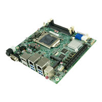
IEI Technology KINO-DH110 User Manual (140 pages)
Brand:
IEI Technology
| Category:
Motherboard
| Size: 3.73 MB
Table of Contents
Table of Contents
5
Introduction
15
Introduction
16
Figure 1-1: KINO-DH110
16
Features
17
Connectors
18
Figure 1-2: Connectors
18
Dimensions
19
Figure 1-3: KINO-DH110 Dimensions (MM)
19
Data Flow
20
Figure 1-4: Data Flow Diagram
20
Technical Specifications
21
Table 1-1: KINO-DH110 Specifications
23
Packing List
24
Anti-Static Precautions
25
Unpacking Precautions
25
Packing List
26
Table 2-1: Packing List
26
Optional Items
27
Table 2-2: Optional Items
28
Connectors
29
Peripheral Interface Connectors
30
KINO-DH110 Layout
30
Figure 3-1: Peripheral Interface Connectors (Front Side)
30
Figure 3-2: Peripheral Interface Connectors (Solder Side)
31
Peripheral Interface Connectors
32
External Interface Panel Connectors
33
Table 3-1: Peripheral Interface Connectors
33
Table 3-2: External Peripheral Connectors
33
Internal Peripheral Connectors
34
Audio Connector
34
Figure 3-3: Audio Connector Location
34
Table 3-3: Audio Connector Pinouts
34
Battery Connector
35
Figure 3-4: Battery Connector Location
35
Buzzer Connector
36
Figure 3-5: Buzzer Connector Location
36
Table 3-4: Battery Connector Pinouts
36
Table 3-5: Buzzer Connector Pinouts
36
Chassis Intrusion Connector
37
Figure 3-6: Chassis Intrusion Connector Location
37
Table 3-6: Chassis Intrusion Connector Pinouts
37
DDR4 SO-DIMM Sockets
38
Figure 3-7: DDR4 SO-DIMM Socket Locations
38
Digital I/O Connector
39
Figure 3-8: Digital I/O Connector Location
39
Table 3-7: Digital I/O Connector Pinouts
39
EC Debug Connector
40
Figure 3-9: EC Debug Connector Location
40
Table 3-8: EC Debug Connector Pinouts
40
Fan Connector (CPU)
41
Figure 3-10: CPU Fan Connector Location
41
Table 3-9: CPU Fan Connector Pinouts
41
Fan Connector (System)
42
Figure 3-11: System Fan Connector Location
42
Table 3-10: System Fan Connector Pinouts
42
Front Panel Connector
43
Figure 3-12: Front Panel Connector Location
43
Table 3-11: Front Panel Connector Pinouts
43
I 2 C Connector
44
Figure 3-13: I 2 C Connector Location
44
Table 3-12: I 2 C Connector Pinouts
44
Internal Displayport Connector
45
Figure 3-14: Internal Displayport Connector Location
45
Table 3-13: Internal Displayport Connector Pinouts
45
Internal Power Connector
46
Figure 3-15: Internal Power Connector Pinout Location
46
Table 3-14: Internal Power Connector Pinouts
46
Keyboard and Mouse Connector
47
Figure 3-16: Keyboard and Mouse Connector Location
47
Table 3-15: Keyboard and Mouse Connector Pinouts
47
LAN LED Connectors
48
Figure 3-17: LAN LED Connector Locations
48
Table 3-16: LAN LED Connector Pinouts
48
Slot
49
Pcie X16 Slot
49
Figure 3-18: M.2 Slot Location
49
Pcie Mini Slot
50
Figure 3-19: Pcie X16 Slot Location
50
Figure 3-20: Pcie Mini Slot Location
50
Table 3-17: Pcie Mini Slot Pinouts
51
Serial Port Connectors
52
Figure 3-21: RS-232 Serial Port Connector Locations
52
Table 3-18: RS-232 Serial Port Connector Pinouts
52
SATA 6Gb/S Drive Connectors
53
Figure 3-22: SATA 6Gb/S Drive Connector Locations
53
Table 3-19: SATA 6Gb/S Drive Connector Pinouts
53
SATA Power Connectors
54
Figure 3-23: SATA Power Connector Locations
54
Table 3-20: SATA Power Connector Pinouts
54
Smbus Connector
55
Figure 3-24: Smbus Connector Location
55
Table 3-21: Smbus Connector Pinouts
55
SPI Flash Connector
56
Figure 3-25: SPI Flash Connector Location
56
Table 3-22: SPI Flash Connector Pinouts
56
SPI Flash Connector, EC
57
Figure 3-26: SPI EC Flash Connector Location
57
Table 3-23: SPI EC Flash Connector Pinouts
57
USB 2.0 Connectors
58
Figure 3-27: USB 2.0 Connector Locations
58
Table 3-24: USB 2.0 Connector Pinouts
58
External Peripheral Interface Connector Panel
59
Audio Connector
59
Figure 3-28: External Peripheral Interface Connector
59
Figure 3-29: Audio Connector
59
Ethernet and USB 3.0 Connectors
60
Table 3-25: USB 3.0 Port Pinouts
60
Table 3-26: LAN Pinouts
60
RS-232/422/485 Serial Port Connectors
61
Figure 3-30: LAN Connector
61
Table 3-27: DB-9 RS-232/422/485 Pinouts
61
HDMI and DP++ Connector
62
Figure 3-31: HDMI Connector
62
Table 3-28: HDMI Connector Pinouts
62
Power Connector (Power Adapter)
63
Figure 3-32: HDMI Connector
63
Figure 3-33: 4-Pin Power Mini-DIN Connector
63
Table 3-29: DP++ Connector Pinouts
63
Installation
64
Anti-Static Precautions
65
Installation Considerations
65
Socket Lga1151 Cpu Installation
67
Figure 4-1: Disengage the CPU Socket Load Lever
67
Figure 4-2: Remove Protective Cover
68
Figure 4-3: Insert the Socket LGA1151 CPU
69
Figure 4-4: Close the Socket LGA1151
69
Socket Lga1151 Cooling Kit Installation
70
Figure 4-5: Cooling Kit Support Bracket
71
So-DIMM Installation
72
Figure 4-6: SO-DIMM Installation (DDR4)
72
Full-Size Pcie Mini Card Installation
73
Figure 4-7: Removing the Retention Screw
73
Figure 4-8: Inserting the Full-Size Pcie Mini Card into the Slot at an Angle
74
Figure 4-9: Securing the Full-Size Pcie Mini Card
74
Module Installation
75
Figure 4-10: Inserting the M.2 Module into the Slot at an Angle
75
Figure 4-11: Securing the M.2 Module
75
System Configuration
76
AT/ATX Power Mode Setting
76
Clear CMOS Button
76
Figure 4-12: AT/ATX Power Mode Switch Location
76
Table 4-1: AT/ATX Power Mode Switch Settings
76
Flash Descriptor Security Override Jumper
77
Figure 4-13: Clear CMOS Button Location
77
Figure 4-14: Flash Descriptor Security Override Jumper Location
77
Table 4-2: Flash Descriptor Security Override Jumper Settings
77
USB Power Selection
78
Table 4-3: BIOS Options and Configured USB Ports
78
Table 4-4: USB Power Source Setup
78
Internal Peripheral Device Connections
79
SATA Drive Connection
79
Figure 4-15: SATA Drive Cable Connection
79
Available Drivers
80
Figure 4-16: IEI Resource Download Center
80
Driver Download
81
Adding Usb 3.0 Drivers to a Windows 7 Installation Image
82
Figure 4-17: Windows 7 USB 3.0 Creator Utility
83
Figure 4-18: Update Process Is Complete
84
Bios
86
Introduction
87
Starting Setup
87
Using Setup
87
Getting Help
88
Unable to Reboot after Configuration Changes
88
BIOS Menu Bar
88
Table 5-1: BIOS Navigation Keys
88
Main
89
Advanced
90
CPU Configuration
91
PCH-FW Configuration
93
ACPI Settings
94
F81866 Super IO Configuration
95
Serial Port N Configuration
96
Serial Port 1 Configuration
96
Serial Port 3 Configuration
97
Serial Port 4 Configuration
98
Iwdd H/W Monitor
99
Smart Fan Mode Configuration
100
RTC Wake Settings
101
Serial Port Console Redirection
102
Legacy Console Redirection Settings
105
Nvme Configuration
106
USB Configuration
107
Iei Feature
108
Chipset
109
System Agent (SA) Configuration
110
Memory Configuration
111
Graphics Configuration
111
PEG Port Configuration
113
PCH-IO Configuration
115
PCI Express Configuration
117
Table 5-2: BIOS Options and Configured USB Ports
117
SATA Configuration
119
HD Audio Configuration
120
Security
121
Boot
122
Save & Exit
124
A Regulatory Compliance
125
B Product Disposal
127
CBIOS Options
129
D Digital I/O Interface
132
Introduction
133
Assembly Language Sample 1
134
Assembly Language Sample 2
134
E Watchdog Timer
135
F Hazardous Materials Disclosure
138
Advertisement
IEI Technology KINO-DH110 Quick Installation Manual (17 pages)
Brand:
IEI Technology
| Category:
Motherboard
| Size: 0.52 MB
Advertisement
Related Products
IEI Technology KINO-DH810
IEI Technology KINO-DH610
IEI Technology KINO-DQM871
IEI Technology KINO-DBT Series
IEI Technology KINO-DCM236
IEI Technology KINO-DQM170-I7-R11
IEI Technology KINO-DQM170-I5-R11
IEI Technology KINO-DQM170-i5-R10
IEI Technology KINO-DQM170-CE-R10
IEI Technology KINO-DQM170-i7-R10
IEI Technology Categories
Motherboard
Touch Panel
Computer Hardware
Single board computers
Desktop
More IEI Technology Manuals
Login
Sign In
OR
Sign in with Facebook
Sign in with Google
Upload manual
Upload from disk
Upload from URL