Sign In
Upload
Manuals
Brands
Husqvarna Manuals
Motorcycle
CR 65 2012
Husqvarna CR 65 2012 Manuals
Manuals and User Guides for Husqvarna CR 65 2012. We have
1
Husqvarna CR 65 2012 manual available for free PDF download: Workshop Manual
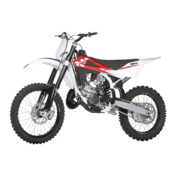
Husqvarna CR 65 2012 Workshop Manual (174 pages)
Brand:
Husqvarna
| Category:
Motorcycle
| Size: 16.23 MB
Table of Contents
Table of Contents
5
1St Edition (09-2011
2
Foreword, Table of Contents
3
Tel. ++39 0332 756 558
3
Workshop Manual
4
Table of Contents
5
Workshop Manual
5
Important Notices
7
Workshop Manual
7
Workshop Manual
8
Workshop Manual
9
Engine
11
Brakes
12
Electrical Components Location
13
General Information
9
Maintenance
15
Troubleshooting
19
Settings and Adjustments
25
Table of Contents
26
Saddle Removal
28
Tank Removal
28
Remove the Chain/Sprocket Cover Protection Casing
29
Throttle Cable Adjustment
29
Carburettor Adjustment
30
Front Brake Fluid Level Check
30
Idle Adjustment
30
Front Brake Lever Adjustment
32
Lever Distance Adjustment
32
Rear Brake Pedal Free Play Adjustment
33
Rear Brake Pedal Position Adjustment
33
Rear Brake Fluid Level Check
34
Oil Level Check
35
Oil Replacement
35
Coolant Level Check
36
Coolant Replacement
36
Air Filter Cleaning and Check
37
Chain Adjustment
38
Chain Cleaning
39
Chain Lubrication
39
Compression Damping Adjustment (LH Fork Leg)
39
Fork Adjustment
39
Rebound Damping Adjustment (RH Fork Leg)
39
Fork Position Adjustment
40
Shock Absorber Spring Preload Adjustment
41
Shock Absorber Hydraulic Damping Adjustment
42
Handlebar Position Change
43
Steering Bearing Clearance Adjustment
43
Exhaust System Check
45
Tank Supply and Breather Pipe Check
45
Sound Deadening Material Replacement
46
General Procedures
49
Table of Contents
50
Foreword
51
Front Mudguard Removal
52
Number Holder Removal
52
Saddle Removal
53
Side Panel Removal
53
Exhaust System Removal
55
Fuel Tank Removal
57
Carburettor Removal from the Engine
58
Radiator Removal
58
Spark Plug Cap Removal
58
Swinging Arm Removal
60
Clutch Actuator Removal
61
Secondary Drive Chain Removal
61
Engine Disassembly
63
Table of Contents
64
Cylinder Head, Cylinder and Piston Removal
65
Gearbox Oil Drainage Procedure
65
Preparation
65
Water Pump Disassembly
66
Clutch Cover Removal
67
Clutch Disassembly
67
Primary Drive Sprocket Removal
68
Gearbox Control Shaft and Selector Plate Removal
69
Kick Start Pedal Shaft Removal
69
Intake Flange and Reed Valve Removal
70
Chain Sprocket Removal
71
Gearbox Control and Shaft Removal
71
Splitting the Crankcase
71
Crankshaft Removal from Casing
72
Process
72
Engine Overhaul
73
Table of Contents
74
Actions on Clutch Cover
78
Crankshaft Measurement
78
Piston and Cylinder Measurement, Piston Assembly Clearance Determination
80
Piston Check
80
Piston Ring Gap Measurement
80
Reed Valve, Intake Flange
81
Gearbox Control Shaft Disassembly
82
Gearbox Control Shaft Pre-Assembly
82
Clutch - Check for Component Wear
83
Plate Pack Pre-Assembly
83
Kick Start Pedal Shaft Pre-Assembly
84
Input Shaft Assembly
85
Output Shaft Assembly
85
Engine Reassembly
87
Table of Contents
88
Inserting the Crankshaft in the Engine Casing
89
Refitting the Kick Start Pedal Shaft
90
Clutch Assembly
91
Refitting the Selector Plate and the Gearbox Control Shaft
91
Refitting the Primary Drive Sprocket
92
Refitting the Chain Sprocket
93
Refitting the Clutch Cover
93
Refitting Reed Valve and Intake Flange
94
Refitting the Ignition System and Adjusting the Fixed Spark Advance
95
Cylinder Head Installation
96
Refitting the Ignition Cover
96
Refitting the Kick Start Pedal
96
Gearbox Oil Filling Procedure
97
Front Suspension
99
Table of Contents
100
Front Suspension
101
Removing Front Fork
102
Fork Oil
103
Fork Spring Features
103
Cleaning the Fork Legs Dust Seals
104
Rear Suspension
105
Brakes
113
Table of Contents
114
Braking System
115
Brake Disc
116
Checking Brake Pads for Wear / Replacing the Pads
117
Pads Installation
117
Pads Removal
117
Bleeding the Front Braking System
118
Bleeding the Rear Braking System
119
Changing the Fluid
120
Electrical System
123
Table of Contents
124
Wiring Diagram
125
Electrical Components Location
126
Spark Plug
127
Handlebar Switches
128
Ignition Coil
128
Ignition System Resistance Values - Stator
128
Left-Hand Switch
128
Ignition Static Parameters Measurement with Peak Voltage Adapter
129
Important
130
Engine Cooling
131
Hydraulically Controlled Clutch
137
Fuel Supply
143
Special Tools
155
Tightening Torque Figures
157
Chassis and Wheels
163
Chassis
165
Lubrication Points (Lubricant)
165
Front Wheel
166
Rear Wheel
169
Wheel Servicing
171
Wheel Axle Warpage
171
Axle Runout over 100 MM
171
Wheel Spokes
172
Wheel Rim Warpage
172
Rear Chain Sprocket, Secondary Drive Sprocket and Chain
173
Advertisement
Advertisement
Related Products
Husqvarna CR 1225 2012
Husqvarna CR125/2007
Husqvarna 2004 CR 250
Husqvarna 2013 CR 125
Husqvarna 2004 CR 125125
Husqvarna CR 125 2009
Husqvarna CR 125 2010
Husqvarna CR 125/2002
Husqvarna CR 250/2003
Husqvarna CR 150 USA 2011
Husqvarna Categories
Lawn Mower
Trimmer
Chainsaw
Motorcycle
Saw
More Husqvarna Manuals
Login
Sign In
OR
Sign in with Facebook
Sign in with Google
Upload manual
Upload from disk
Upload from URL