Sign In
Upload
Manuals
Brands
Honeywell Manuals
Voice Recorder
DR4321
Honeywell DR4321 Manuals
Manuals and User Guides for Honeywell DR4321. We have
1
Honeywell DR4321 manual available for free PDF download: Product Manual
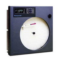
Honeywell DR4321 Product Manual (266 pages)
Circular Chart Recorder
Brand:
Honeywell
| Category:
Voice Recorder
| Size: 2.14 MB
Table of Contents
5
Table of Contents
13
1 Overview
13
Introduction
16
Model Number Breakdown
21
About This Manual
22
Figure 1-1 Guide to Manual's Organization
23
2 Installation
23
Overview
24
Table 2-1 Operating Limits and Condensed Specifications
27
Mounting Considerations and Overall Dimensions
27
Figure 2-1 Overall Dimensions
28
Mounting Methods
28
Introduction
28
Figure 2-2 Plug Locations
29
Mounting Flush in Panel (New Panel Cutout)
29
Table 2-2 Mounting Flush in a New Panel Cutout
29
Figure 2-3 Mounting Flush in a New Panel Cutout (Rear View)
30
Panel Mounting Recorder with NEMA4 or Heavy Duty Door
30
Table 2-3 Procedure for Mounting Recorder with NEMA4 or Heavy Duty Door
31
Figure 2-4 Panel Mounting Recorder with NEMA4 or Heavy Duty Door
32
Mounting On a 2-Inch Pipe
32
Table 2-4 Pipe Mounting Procedure
32
Figure 2-5 Pipe Mounting Brackets
33
Mounting On Surface (Of Panel or Wall)
33
Table 2-5 Mounting Flush On a Surface (Of Panel or Wall)
34
Wiring Prerequisites
34
Figure 2-6 Mounting Flush On a Surface of Panel or Wall (Rear View)
36
Figure 2-7 Recommended Wiring Routing - Models Without CE Mark
37
Figure 2-8 Recommended Wiring Routing - Models with CE Mark
38
Table 2-6 Wiring Bundling Categories
38
Table 2-7 Wiring Illustrations
39
Input Wiring
39
Power Wiring
40
Table 2-8 Procedure for Power Wiring Models
41
Figure 2-9 Power Wiring - Models Without CE Mark
42
Figure 2-10 Power Wiring - Models with CE Mark
43
Analog Input Wiring
43
Table 2-9 Analog Input Wiring
44
Figure 2-11 Analog Input Wiring
45
Digital Inputs (Optional)
45
Table 2-10 Digital Input Wiring
46
Figure 2-12 Digital Input Wiring
47
Communication (Optional)
47
Table 2-11 Communication Wiring
48
Figure 2-13 Communication Wiring
49
Output Wiring
49
Discrete Outputs
49
Table 2-12 Output Terminal Use for Output Algorithm and Option Combinations
50
Table 2-13 Relay Output Wiring - 1 or 2 Pen Models
51
Figure 2-14 Relay Output Wiring
52
Figure 2-15 Open Collector Output Wiring
53
Current Output
53
Table 2-14 Current Output Wiring
54
Figure 2-16 Current Output Wiring
55
Transmitter Power Out
55
Table 2-15 Transmitter Power Out Wiring
56
Figure 2-17 Transmitter Power Out Wiring
57
3 Configuration, Startup, and Operation of Basic Recorder Without Display
57
Overview
58
Configuration (Recording Set Up)
58
Setting Configuration and Input Switches
58
Table 3-1 Procedure for Configuring Model Without Display
59
Figure 3-1 Location of Configuration and Input Switches
60
Figure 3-2 Sample Chart for Single Pen Recorder
61
Table 3-2 Configuration and Input Switch Settings for Models Without Display
76
Setting SW6 Switch 2
77
Startup and Operation of Recorder Without Display
77
Overview
78
Preparing the Recorder for Operation
78
Table 3-3 Preparing the Recorder for Operation
78
Figure 3-3 Basic Chart Plate Components
79
Running the Optional Step Test
79
Table 3-4 Procedure for Running the Step Test
80
Figure 3-4 Typical Step Test Chart Patterns
81
Startup
81
Table 3-5 Startup Procedure
81
Figure 3-5 Setting Chart Time to Time Index
83
4 Configuration, Startup and Operation of Recorder with Display
83
Overview
84
Operator Interface On Recorder with Display and Keypad
84
Figure 4-1 Operator Interface
85
Table 4-1 Key Functions
86
Configuration (Recording and Output Set Up)
86
Overview
87
Configuration Prompts
87
Figure 4-2 Prompt Hierarchy
89
How to Get Started
90
Configuration Tips
90
Table 4-2 Configuration Tips
91
Switch Settings
92
Table 4-3 SW6 Input Switch Settings for Models Having Display and Keypad
94
Figure 4-3 Location of Switches and Relays
95
Configuration Procedure
95
Table 4-4 Configuration Procedure
97
Input Parameters Set Up Group
97
Table 4-5 Input Parameter Definitions
101
Pen Parameters Set Up Group
101
Table 4-6 Pen Parameter Definitions
102
Chart Parameters Set Up Group
102
Table 4-7 Chart Parameter Definitions
103
Totalizer Parameters Set Up Group
103
Table 4-8 Totalizer Function Definitions
106
Control Parameters Set Up Group
106
Table 4-9 Control Parameter Definitions
112
Tuning Parameters Set Up Group
113
Table 4-10 Tuning Parameter Definitions
116
Setpoint Ramp/Program Set Up Group
116
Table 4-11 Setpoint Ramp Parameter Definitions
117
Timer Set Up Group
117
Table 4-12 Timer Parameter Definitions
118
Alarms Set Up Group
118
Table 4-13 Alarm Parameter Definitions
121
Auxiliary Output Set Up Group
121
Table 4-14 Auxiliary Output Parameter Definitions
123
Communication Set Up Group
123
Table 4-15 Communication Parameter Definitions
124
Remote Switch (Digital Inputs) Set Up Group
125
Table 4-16 Remote Switch Parameter Definitions
126
Display Parameter Set Up Group
126
Table 4-17 Display Parameter Definitions
127
Lock Out Parameter Set Up Group
127
Table 4-18 Lockout Parameter Definitions
128
Configuration Record Sheet
130
Limit Control Configuration
130
Table 4-19 Limit Control Parameter Definitions
131
Startup of Recorder with Display and Keypad
131
Overview
132
Preparing the Recorder for Startup
132
Table 4-20 Preparing the Recorder for Operation
132
Figure 4-4 Basic Chart Plate Components
133
Running the Optional Step Test
133
Table 4-21 Procedure for Running the Step Test
134
Figure 4-5 Typical Step Test Chart Patterns
135
Completing Preparation and Startup
135
Table 4-22 Procedure for Setting Chart Time and Applying Power
135
Figure 4-6 Setting Chart Time to Time Index
136
Table 4-23 Power-Up Diagnostic Tests
137
Table 4-24 Procedure for Testing the Displays and Keys
138
Table 4-25 Procedure for Starting the Recorder
140
Operation of Recorder with Display and Keypad
140
Monitoring Your Recorder
140
Figure 4-7 Operator Interface
141
Table 4-26 Meaning of Indicators
142
Table 4-27 Lower Display Operating Parameter Labels
143
Table 4-28 Error Messages
144
Operator Functions
145
Table 4-29 Procedure for Selecting Automatic or Manual Mode
146
Table 4-30 Procedure for Changing the Control Setpoints
147
Table 4-31 Procedure for Displaying or Changing the Alarm Setpoints
148
Table 4-32 Procedure for Selecting Factory or Field Calibration Values
149
Table 4-33 Procedure for Resetting Totalizer
150
Table 4-34 Procedure for Starting Timer
151
Table 4-35 Procedure for Resetting Limit Controller
153
5 Input and Output Calibration for Recorder with Display
153
Overview
154
Input Calibration Minimum and Maximum Range Values
155
Table 5-1 Voltage and Resistance Equivalents for 0 % and 100 % Range Values
156
Input Calibration Preliminary Information
156
Table 5-2 Equipment Needed for Calibration
157
Table 5-3 Disconnect the Field Wiring
157
Figure 5-1 Location of the Input Connections On the Input Boards
158
Input Calibration Set Up and Wiring
158
General Calibration Set Up
158
Table 5-4 General Calibration Set Up Procedure
158
Figure 5-2 Calibration Set Up Diagram for Thermocouple Inputs Using a Compensated Calibrator
158
Figure 5-3 Calibration Set Up Diagram for Thermocouple Inputs Using an Ice Bath
158
Figure 5-4 Calibration Set Up Diagram for RTD Inputs
159
Thermocouple Inputs Using a Compensated Calibrator
159
Table 5-5 Set Up Wiring Procedure for Thermocouple Inputs Using a Compensated Calibrator
160
Thermocouple Inputs Using an Ice Bath or Ice Point Reference
160
Table 5-6 Set Up Wiring Procedure for Thermocouple Inputs Using an Ice Bath
161
RTD (Resistance Temperature Detector) Inputs
161
Table 5-7 Set Up Wiring Procedure for Calibrating RTD Inputs
162
Table 5-8 Set Up Wiring Procedure for Calibrating Millivolts, Volts, and Milliamps Inputs
162
Figure 5-5 Calibration Set Up Diagram for Millivolts, Volts, and Milliamps Inputs
163
Input Calibration Procedure
163
Table 5-9 Input Calibration Procedure Sequence
165
Current Output Calibration
165
Table 5-10 Set Up Wiring Procedure for Current Proportional Output
165
Figure 5-6 Test Equipment Connections for Calibrating Current Output
166
Table 5-11 Procedure for Calibrating Current Output
169
6 Routine Maintenance
169
Overview
170
Replacing the Chart
170
Table 6-1 Procedure for Replacing the Chart
170
Figure 6-1 Replacing the Chart and Ink Cartridge
171
Replacing the Ink Cartridge
171
Table 6-2 Procedure for Replacing the Ink Cartridge
172
Maximizing Pen Life
172
Table 6-3 Maximizing Pen Life
173
7 Troubleshooting and Pen Alignment of Basic Recorder Without Display
173
Overview
175
Observable Symptoms of Failure
175
Table 7-1 Observable Symptoms of Failure
176
Troubleshooting Procedures
176
Overview
177
Recorder Failure Troubleshooting
177
Table 7-2 Troubleshooting Recorder Failure Symptoms
178
Pen Trace Troubleshooting
178
Table 7-3 Troubleshooting Pen Trace Failure Symptoms
179
Chart Rotation Troubleshooting
179
Table 7-4 Troubleshooting Chart Rotation Failure Symptoms
180
Troubleshooting Erratic Pen Movement
180
Table 7-5 Troubleshooting Erratic Pen Movement Symptoms
181
Alignment of Pen at Zero and 100
181
Table 7-6 Procedure for Pen Alignment
183
8 Troubleshooting and Pen Alignment of Recorder with Display
183
Overview
185
Troubleshooting Aids
185
Table 8-1 Procedure for Identifying the Software Version
186
Self Diagnostics
186
Power Up Tests
186
Table 8-2 Power-Up Diagnostic Tests
187
View Status of Tests
187
Table 8-3 Procedure for Displaying the Results of Self-Diagnostics
188
Background Tests
188
Error Messages
189
Table 8-4 Error Messages
191
Observable Symptoms of Failure
191
Table 8-5 Observable Symptoms of Failure
192
Troubleshooting Procedures
192
Overview
193
Recorder Failure Troubleshooting
193
Table 8-6 Troubleshooting Recorder Failure Symptoms
194
Pen Trace Troubleshooting
194
Table 8-7 Troubleshooting Pen Trace Failure Symptoms
195
Chart Rotation Troubleshooting
195
Table 8-8 Troubleshooting Chart Rotation Failure Symptoms
196
Troubleshooting Erratic Pen Movement
196
Troubleshooting the Keypad and Display
196
Table 8-9 Troubleshooting Erratic Pen Movement Symptoms
196
Table 8-10 Troubleshooting Keypad And/Or Display Failure Symptoms
197
Troubleshooting Relay Output
197
Table 8-11 Troubleshooting Relay Output Failure Symptoms
198
Troubleshooting External Alarm Function
198
Troubleshooting Remote Switch (Digital Input) Function
198
Table 8-12 Troubleshooting External Alarm Function Failure Symptoms
198
Table 8-13 Troubleshooting Remote Switch (Digital Input) Function Failure Symptoms
199
Troubleshooting Modbus Communications
199
Table 8-14 Troubleshooting Modbus Communications
200
Alignment of Pen at Zero and Span
200
Table 8-15 Procedure for Aligning Pen at Zero and Span
203
9 Parts List
203
Overview
203
Figure 9-1 Door Assembly
203
Figure 9-3 Recorder Components
204
Exploded Views
204
Table 9-1 Door Assembly Parts
205
Table 9-2 Chart Plate Assembly Parts
205
Figure 9-2 Chart Plate Assembly
207
Table 9-3 Basic Recorder Parts
208
Figure 9-4 DR4300 Recorder (CE Mark) - Internal Cabling Diagram
209
Figure 9-5 DR4300 Recorder (Non-Ce Mark) - Internal Cabling Diagram
211
Accuracy
211
Overview
212
Typical Reference Accuracy
212
Table A-1 Typical Reference Accuracy
215
Available 10-Inch Charts
215
Single Range Charts
215
Table B-1 10-Inch Single Range Chart Part Numbers
221
Dual Range Charts
221
Table B-2 10-Inch Dual Range Chart Part Numbers
225
Setpoint Ramp/Soak Programming and Operation
225
Overview
226
Program Contents
228
Drawing a Ramp/Soak Profile
228
Figure C-1 Ramp/Soak Profile Example
232
Setpoint Program Prompt Hierarchy
232
Table C-1 Prompt Hierarchy and Available Selections
235
Run/Monitor the Program
235
Table C-2 Run/Monitor Functions
239
Using Accutune II
239
Overview
240
Starting and Stopping Tuning with Accutune II
240
Table D-1 Procedure for Starting Accutune II
241
Using Accutune with Duplex (Heat/Cool) Control
241
Table D-2 Procedure for Using Accutune for Duplex Control
243
Foreign Language Safety Instructions
245
4/00 DR4300 Circular Chart Recorder Product Manual
255
Honeywell Service Centers
Advertisement
Share and save
Advertisement
Related Products
Honeywell DR4300 Series
Honeywell DR4500
Honeywell DR4301
Honeywell DR4302
Honeywell DR4322
Honeywell DR4311
Honeywell DR4312
Honeywell DR4332
Honeywell DR4331
Honeywell DPR180
Honeywell Categories
Thermostat
Controller
Security Camera
Control Unit
Accessories
More Honeywell Manuals
×
Login
Sign In
OR
Sign in with Facebook
Sign in with Google
×
Upload manual
Upload from disk
Upload from URL