Sign In
Upload
Manuals
Brands
Hitachi Manuals
Air Conditioner
RAS-8HRNM
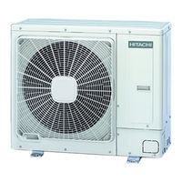
User Manuals: Hitachi RAS-8HRNM Air Conditioning System
Manuals and User Guides for Hitachi RAS-8HRNM Air Conditioning System. We have
3
Hitachi RAS-8HRNM Air Conditioning System manuals available for free PDF download: Service Manual
Hitachi RAS-8HRNM Service Manual (578 pages)
Brand:
Hitachi
| Category:
Air Conditioner
| Size: 47 MB
Table of Contents
Table of Contents
8
Fan Units
29
Transportation of Outdoor Unit
31
Center of Gravity
31
Place Provision
33
Specifications
37
Right Side
49
Front Panel
49
Factory-Supplied Accessories
52
Single Installation
53
Multiple Installation
53
Lower Right
59
Initial Check
62
Installation
64
Suspension Bolts
64
Air Panel Installation
66
Indoor Unit
83
Rpc-(2.0~6.0)Fsn2E
85
Rpi(M)-(1.5~6.0)Fsn2E
89
Factory-Supplied Accessories
89
Initial Check
89
Unit Installation
90
Connecting Field Supply Duct and Suction Air Filter Servicing
91
Air Suction Direction Change
93
Rpk-(1.5~4.0)Fsn2M
94
Factory Supplied-Accessories
94
Initial Check
94
Unit Installation
95
Dimension of the Mounting Bracket
100
Rpf(I)-(1.5~2.5)Fsn2E
101
Factory Supplied-Accessories
101
Initial Check
101
Installation
102
Complementary Systems
105
KPI. Energy Recovery Ventilation Units
105
Relative Humidity
107
Optional Accessories
111
Fresh Air Intake
111
Branch Discharge
114
Filters
116
Specifications
118
General Notes
122
Piping Work Connection Considerations
123
Piping Materials
123
Three Principles on Refrigerant Piping Work
125
Suspension of Refrigerant Piping
126
Brazing Work
126
Refrigerant Charge
128
Caution of the Pressure by Check Joint
128
Refrigerant Charge Quantity
129
Pump down Refrigerant
130
Outdoor Units
131
Piping Connection
131
Refrigerant Piping Length
135
Refrigerant Piping Selection
135
Twin and Triple System Installation
136
Drain Discharging Boss
138
Applicable Model
138
Indoor Units and Complementary Systems
139
Rci-(1.5~6.0)Fsn2E
139
Rcim-(1.5-2.0)Fsn2
140
Rcd-(1.5~5.0)Fsn2
142
Rpc-(2.0~6.0)Fsn2E
143
Knockout Hole
144
Rear Side Connection
145
Drain Piping
145
Piping Connection
149
Gas Piping Connection
156
General Check
164
Electrical Wiring Connection for the Outdoor Unit
164
Setting the DIP Switches for the Outdoor Unit
165
Electrical Wiring Connection
170
Cable Tie
171
RPF\RPFI Units
179
Electrical WIRING between Indoor UNIT and Outdoor UNIT
187
Wire Sizes
189
H-Link System
191
Outdoor Unit
191
Electrical Wiring Diagrams
201
DEVICE Control SYSTEM
224
Indoor UNIT PCB
226
Switch Indication
229
Outdoor UNITS PCB
231
Protection and SAFETY Control
232
Oil Heater
232
STANDARD Operation SEQUENCE
234
Cooling Operation
234
Dry Operation
236
Heating Operation
238
Defrost Operation Control
240
STANDARD Control Functions
241
Freezing Protection During Cooling Process or Dry Operation
241
P Revention Control for Excessively High Discharge Gas Temperature
242
Activation for Protection Device Control
245
Preheating Control of Compressor
248
Prevention Control for High Pressure Increase
248
Available Optional Functions
249
Indoor Units
250
Available Ports
250
Description of Optional Input Signals
256
Description of Optional Output Signals
259
Econofresh KIT
260
Input Connections
261
Output Connections
261
Input Signals
263
Output Signals
263
Optional Functions
266
Optional Function Setting
271
Alarm Indication
285
Optional Functions Available through Wireless Remote Control SWITCH (PC-Lh3A + RECEIVER)
286
CHECKING Procedure before the TEST RUN
288
TEST RUN Procedure USING the Remote Control SWITCH
290
TEST RUN Procedure USING the Wireless Remote Control SWITCH
291
TEST RUN Procedure from the Outdoor UNIT SIDE
293
Cooling Operation
295
Heating Operation
295
Initial Troubleshooting
304
Checking Using the 7-Segment Display
304
Failure of the Power Supply to the Indoor Unit and the Remote Control Switch
305
Abnormal Transmission between the Remote Control Switch and the Indoor Unit
306
Abnormal Operation of the Devices
307
Troubleshooting Procedure
315
Alarm Code
315
Troubleshooting by Alarm Code
317
Thermistor Characteristics
332
Thermistor Characteristics
359
Compressor Protection
361
Troubleshooting in Check Mode
362
Temperature Indication
363
Troubleshooting Using the 7 Segment Display
368
Cause of Inverter Stoppage
370
Protection Control
371
Procedure for CHECKING each MAIN PART
373
Self-Checking Procedure of the Indoor Unit PCB (Only for RPK)
377
Confirmation Method
377
Procedure of Checking Other Main Parts
378
Check List on Compressor
389
Spare Parts
391
Rpc-(2.0~6.0)Fsn2E
396
Electrical Equipment
418
Outdoor UNIT RAS-3HVRNME
426
Removing Service Cover
426
Removing Air Outlet Grille
426
Removing Upper Cover
427
Removing Outdoor Fan Motor
427
Removing the Compressor
428
Removing Reversing Valve Coil
432
Removing Expansion Valve Coil
433
Removing Reversing Valve
434
Removing Expansion Valve
434
Removing Solenoid Valve
435
Removing Electrical Components
436
Removing Other Electrical Components
438
Removing Service Cover
439
Removing Air Outlet Grille
439
Removing Upper Cover
440
Removing Outdoor Fan Motor
441
Removing the Compressor
442
High Pressure Switch
445
R Emoving Expansion Valve Coil
448
Removing Reversing Valve
449
Removing Electrical Components
451
Terminal Board
452
Removing Other Electrical Components
453
Removing Outdoor Fan Motor
456
Removing Inverter Components
467
Removing Diode Module and Transistor Module
468
Removing Other Electrical Components
469
Rci-(1.5~6.0)Fsn2E
470
Removing the Long Life Filter
470
Removing the Air Intake Grille
470
Removing the Electrical Box Cover
471
Removing the Optional Air Panel
471
Removing the Fan Runner and Fan Motor
471
Removing the Bell-Mouth
472
Removing the Printed Circuit Board (PCB)
472
Removing the Drain Pan
473
Removing the Drain-Up Mechanism
473
Removing the Float Switch
473
Removing the Thermistor for Liquid Pipe and Gas Pipe
474
Removing the Electronic Expansion Valve Coil
474
Removing the Automatic Louver Motor
475
Rcim-(1.5-2.0)Fsn2
476
Removing the Air Filter
476
Removing the Air Intake Grille
476
Removing the Optional Air Panel
477
Removing the Fan Runner and Fan Motor
478
Removing the Bell-Mouth
478
Removing the Printed Circuit Board (PCB)
479
Removing the Drain Pan
479
Removing the Drain-Up Mechanism
480
Removing the Float Switch
481
Removing the Thermistor for Liquid Pipe and Gas Pipe
482
Removing the Electronic Expansion Valve Coil
482
Removing the Automatic Louver Motor
483
Rcd-(1.5~5.0)Fsn2
484
Removing the Long-Life Filter and the Air Inlet Grille
484
Removing the Electrical Box Panel
484
Removing the Optional Air Panel
484
Removing the Fan Runner and the Fan Motor
485
Removing the Printed Circuit Board (PCB)
486
Removing the Float Switch
486
Removing the Drain-Up Mechanism
486
Removing the Drain Pan
487
Removing the Thermistor for Liquid Pipe and Gas Pipe
488
Removing the Electronic Expansion Valve Coil
488
Removing the Automatic Louver Motor
490
Rpi-(1.5~6.0)Fsn2E
491
Removing the Electrical Box and Electrical Parts
491
Removing the Inlet Air Thermistor
491
Removing the Outlet Air Thermistor
492
Removing the Liquid and Gas Pipe Themistors
492
Removing the Fan Parts
493
Removing the Drain Pump
493
Removing the Float Switch
494
Removing the Air Filter
494
Rpim 1.5 Fsn2E
495
Electrical Parts
495
Rpc-(2.0~6.0)Fsn2E
498
Removing the Air Filter
498
Removing the Side Panel
498
Removing the Discharge Air Grille
498
Removing the Fan Motor
499
Removing the Bearing
500
Removing the Coupling
500
Removing the Automatic Louver Motor
500
Removing the Thermistors for Liquid Pipe and Gas Pipe
501
Removing the Printed Circuit Board (PCB)
501
Heat Exchanger
501
Rpk-(1.5-2.0)Fsn2M
502
Removing the Air Filter
502
Removing the Front Panel
502
Removing the Motor for the Automatic Louver
505
Removing the Thermistor for Liquid Pipe, Gas Pipe, Discharged Air and Suction Air
505
Removing the Electrical Box Panel
506
Removing the Drain Pan
507
Removing the Heat Exchanger
507
Removing the Fan Motor
508
Removing the Electronic Expansion Valve
509
Rpk-(2.5~4.0)Fsn2M
511
Air Filter
511
Removing the Right Side Cover
512
Removing the Thermistors for Liquid Pipe, Gas Pipe, Discharge Air and Suction Air
513
Removing the Drain Pan
514
Removing the Electrical Box Panel
516
Removing the Heat Exchanger
516
Removing the Fan and the Fan Motor
517
Removing the Suction Air Grille
518
Removing the Electronic Expansion Valve Coil
519
Rpf-(1.5~2.5)Fsn2E
521
Removing the Air Inlet Grille
521
Removing the Air Filter
521
Removing the Discharge Air Grille
521
Removing the Front Panel
521
Removing the Fan Motor
522
Removing the Printed Circuit Board (PCB)
523
Removing the Thermistors for Liquid Pipe and Gas Pipe
523
Rpfi-(1.5~2.5)Fsn2E
524
Removing the Air Filter
524
Removing the Front Panel
524
Removing the Fan Motor
524
KPI - Energy Recovery Ventilation Units
525
Structure and Parts Names
525
Standard Connection System and Central Station
526
Controlled Network System
527
Filter Maintenance
529
Energy Recovery Ventilation Units Element Cleaning
530
Energy Recovery Ventilation Units Fan Units and Connectors
531
Cleaning the Indoor Heat Exchanger
532
Required Tools for Cleaning (for All Indoor Units)
532
Cleaning the 4-Way Cassette Indoor Unit
534
Drain Pan
536
Cleaning the 2-Way Cassette Indoor Unit
537
Cleaning the Wall Type Indoor Unit
539
Cleaning the Floor Type Indoor Unit and the Floor Concealed Type Indoor Unit
540
Cleaning the Ceiling Type Indoor Unit
542
Collecting Refrigerant for Replacing Indoor Unit
543
Inverter
546
Specifications of Inverter
546
Inverter Time Chart
548
Protective Function
549
Overload Control
550
AC Chopper
551
Thermistor
553
Operation
554
Electronic Expansion Valve
555
Electronic Expansion Valve for the Outdoor Unit
555
Specifications
555
Electronic Expansion Valve for the Indoor Unit
556
High Pressure Protection Device
557
Noise Filter (NF)
558
Capacitor (CB1, CB2)
559
Reactor (DCL)
559
Auto Louver Mechanism
560
RCI (4-Way Cassette Type)
560
RCD (2-Way Cassette Type)
561
RPC (Ceiling Type)
562
Scroll Compressor
563
Reliable Mechanism for Low Vibrating and Low Sound
563
Principle of Compression
563
Field Work Instruction
565
Checking the Power Source and the Wiring Connection
566
Burnt-Out Compressor Due to an Insufficient Refrigerant Charge
566
Insufficient Cooling Performance When a Long Piping Is Applied
567
Abnormally High Operation Sound (In-The-Ceiling Type Indoor Unit)
567
Alarm Code "31
568
Not Cooling Well Due to Insufficient Installation Space for the Outdoor Unit
568
Guideline for Selecting the Drain Pipe for the Indoor Unit
569
Caution with the Refrigerant Leakage
570
Maximum Permissible Concentration of the HCFC Gas
570
Calculation of the Refrigerant Concentration
570
Countermeasure for the Refrigerant Leakage According to the KHK Standard
570
Maintenance Work
571
Service and Maintenance Record
572
SERVICE and MAINTENANCE Record USING the 7-SEGMENT Display
573
Service and Maintenance Record by Remote Control Switch
574
Pump-Down Method for Replacing the Compressor
575
Advertisement
Hitachi RAS-8HRNM Service Manual (413 pages)
Brand:
Hitachi
| Category:
Air Conditioner
| Size: 42 MB
Table of Contents
Complementary Systems
7
Table of Contents
11
Units Installation
13
Transportation of Outdoor Unit
14
Hanging Method
14
Rci
15
Factory-Supplied Accessories
15
Initial Check
15
Installation
16
Air Panel Installation
17
Rcim-Fsn
19
Factory-Supplied Accessories
19
Initial Check
19
Installation
20
Air Panel Installation
21
Rcd
22
Factory-Supplied Accessories
22
Initial Check
22
Installation
23
Rpc
26
Factory-Supplied Accessories
28
Initial Check
28
Installation
28
RPI (In-The-Ceiling)
28
Unit Installation
28
Air Suction Direction Change
30
Rpk
31
Factory-Supplied Accessories
31
Initial Check
31
Dimensions of the Mounting Bracket
33
RPF (Floor Type) / RPFI (Floor-Concealed Type)
34
Factory-Supplied Accessories
36
Initial Check
36
Installation
36
Complementary Systems
36
KPI (Total Heat Exchanger)
36
Econofresh Kit
38
Ras Hrnm
39
Installation Space
39
Single Installation
40
Multiple Installation
40
Installation Place Provision
41
Installation of Wind Ward and Snow Protection Hood
42
Air Flow Guide, Wind Guard and Snow Protection Hood
42
Service Space
43
Optional Accessories
46
Piping Installation
52
General Notes
52
Piping Work Connection Considerations
53
Piping Materials
53
Three Principles on Refrigerant Work
54
Suspension of Refrigerant Piping
55
Tightening Torque
55
Brazing Work
55
Indoor Units and Complementary Systems
57
Rci - 4 Way Cassette Type
57
Rcd - 2 Way Cassette Type
57
Rci
57
Rcim
58
Gas Piping
58
Liquid Piping
58
Rcd
59
Rpc
60
Rpc - Ceiling Type
60
Rpi
62
Rpk
64
Rpk - Wall Type
64
Rpf & Rpfi - Floor Type & Floor Concealed Type
64
Rpf(I)
66
Refrigerant Piping
66
Outdoor Units
67
Factory Supplied Pipe Accessories
67
Piping Connection
67
Vacuum and Refrigerant Charge
69
Drain Discharge Boss
70
Electrical Wiring
70
General Check
72
Electrical Wiring for the Outdoor Unit
72
Electrical Wiring Connection for Outdoor Unit
72
Setting the Dip Switches for the Outdoor Unit
73
Electrical Wiring for the Indoor Unit
75
Electrical Wiring Connection
76
Electrical Wiring between Indoor Unit and Outdoor Unit
85
Wire Sizes
87
H-LINK System
88
Psc-5Hr
90
Internal Layout
90
Electrical Wiring Diagrams
92
Remote Control Switch
106
Installation
106
Safety Summary
135
Component Names
135
Specifications
136
Control System
140
Device Control System
140
Indoor Unit PCB
142
Layout of the Printed Circuit Board for RCI
143
Layout of the Printed Circuit Board for RCD
143
Layout of the Printed Circuit Board for RPI1.5~6.0, RPC, RPF(I)
144
Layout of the Printed Circuit Board for RPI-8/10
145
Layout of the Printed Circuit Board for RPK FSNM
146
Complementary System
147
Kpi
147
Led Indication
147
Outdoor Units PCB
148
Protection and Safety Control
149
Safety and Control Device Setting
149
Standard Operation Sequence
150
Cooling Operation
150
Dry Operation
152
Heating Operation
154
Defrost Operation Control
156
Standard Control Functions
157
Freezing Protection Control During Cooling Process or Dry Operation
157
Prevention Control for Excessively High Discharge Gas Temperature
158
Indoor Unit Electrical Expansion Valve Control
159
Time Chart
159
Outdoor Unit Electrical Expansion Valve Control
160
Outdoor Fan Control During Cooling Operation
162
Outdoor Fan Control During Heating Operation
163
Preheating Control of Compressor
164
Prevention Control for High Pressure Increase
164
Indoor Units
166
Available Ports
166
Description of Optional Input Signals
170
Description of Optional Output Signals
172
Configuration
173
Alarm Signal
176
Econofresh Kit
177
Description of Optional Input Signals
177
Compatibilities
177
HRNM Outdoor Units
178
Available Ports
178
Configuration
179
Available Optional Signals
179
Setting of the Optional Signals
180
Description of Optional Input Signals
181
Description of Optional Output Signals
182
Optional Functions
182
Available Optional Functions
183
Optional Functions Setting
186
Optional Functions Available through the Remote Control Switch (PC-P5H)
186
Optional Functions Available through Wireless Remote Control Switch (PC-LH3A + Receiver)
194
Test Run
196
Checking Procedure before the Test Run
196
Test Run Procedure by Means of the Remote Control Switch
197
Test Run Procedure by Means of the Wireless Remote Control (PC-LH3A)
198
Test Run Procedure from the Outdoor Unit Side
200
Operation
200
Check List
201
Troubleshooting
207
Failure of the Power Supply to the Indoor Unit and the Remote Control Switch
209
Abnormal Transmission between the Remote Control Switch and the Indoor Unit
210
Abnormal Operation of the Devices
211
Troubleshooting Procedure
219
Troubleshooting by Alarm Code
221
Troubleshooting
252
Compressor Protection
256
Troubleshooting by Means of the 7-Segment Display
263
Troubleshooting by Means of the Flashing Alarm Leds for Rpk-Fsnm
265
Cause of Inverter Stoppage
265
Protection Control
266
Procedure for Checking each Main Part
268
Self-Checking Procedure of Pcb by Means of the Remote Control Switch
268
Self-Checking Procedure of the Indoor Unit Pcb (Only for Rpk)
272
Procedure of Checking Other Main Parts
273
Power Consumption
279
Resistance (Ω)
280
Check List on Compressor
281
Spare Parts
283
Cycle and Structural Parts
295
Parts List
298
Removing Air Outlet Grille
301
Removing Upper Cover
302
Removing Outdoor Fan Motor
303
Opening Electrical Box (P-Mounting Plate)
308
Phillips Screwdriver
308
Removing Expansion Valve Coil
310
Removing Reversing Valve
311
Diode Module
315
Rci
317
Way Cassette
317
Removing the Long Life Filter
317
Removing the Air Intake Grille
317
Removing the Electrical Box Cover
317
Servicing
317
Removing the Optional Air Panel
318
Removing the Fan Runner and Fan Motor
318
Removing the Bell-Mouth
319
Removing the Printed Circuit Board (PCB)
319
Removing the Drain Pan
320
Removing the Drain-Up Mechanism
320
Removing the Float Switch
320
Removing the Thermistor for Liquid Pipe and Gas Pipe
321
Removing the Electronic Expansion Valve Coil
321
Removing the Automatic Louver Motor
322
Rcim - Fsn
323
Removing the Air Filter
323
Removing the Air Intake Grille
323
Removing the Electrical Box Cover
323
Removing the Optional Air Panel
324
Removing the Fan Runner and Fan Motor
325
Removing the Bell-Mouth
325
Removing the Printed Circuit Board (PCB)
326
Removing the Drain Pan
326
Removing the Thermistor for Liquid Pipe and Gas Pipe
329
Removing the Automatic Louver Motor
331
Rcd
332
Rpi In-The Ceiling Type
339
Removing the Electrical Box and Electrical Parts
339
Removing Inlet Air Thermistor
339
Removing the Liquid and Gas Pipe Thermistors
340
Removing the Fan Parts
341
Removing the Drain Pump
341
Removing the Float Switch
342
Removing the Air Filter
342
Rpc
343
Removing the Air Filter
343
Removing the Side Panel
343
Removing the Discharge Air Grille
343
Removing the Fan Motor
344
Removing the Bearing
345
Removing the Coupling
345
Rpk-1.5/2
347
Removing the Air Filter
347
Removing the Front Panel
348
Removing the Motor for the Automatic Louver
349
Removing the Thermistor for Liquid Pipe, Gas Pipe, Discharged Air and Suction Air
349
Removing the Electrical Box Panel
350
Removing the Drain Pan
351
Removing the Heat Exchanger
351
Removing the Fan Motor
352
Removing the Electronic Expansion Valve
353
Rpk-2.5~4.0
355
Removing the Right Side Cover
356
Removing the Thermistors for Liquid Pipe, Gas Pipe, Discharge Air and Suction Air
357
Removing the Drain Pan
358
Heat Exchanger
358
Removing the Electrical Box Panel
359
Removing the Heat Exchanger
360
Removing the Suction Air Grille
362
Removing the Electronic Expansion Valve Coil
363
Rpf
365
Floor Type
365
Removing the Air Inlet Grille
365
Removing the Air Filter
365
Removing the Discharge Air Grille
365
Removing the Front Panel
366
Removing the Fan Motor
366
Removing the Printed Circuit Board (PCB)
367
Rpfi
368
Floor-Concealed Type
368
Removing the Air Filter
368
Removing the Front Panel
368
Removing the Fan Motor
369
Removing the Printed Circuit Board (PCB)
369
Optional Function
370
Total Heat Exchanger
370
Structure
370
Removing Electrical Parts
370
Removing Air Filter and Total Heat Exchanger Element
371
Removing Fan Motor
372
Cleaning the Indoor Heat Exchanger
373
Required Tools for Cleaning (for All Indoor Units)
373
Cleaning the 4-Way Cassette Indoor Unit
375
Cleaning the 2-Way Cassette Indoor Unit
378
Cleaning the Wall Type Indoor Unit
380
Cleaning the Ceiling Type Indoor Unit
382
Collection Refrigerant for Replacing Indoor Unit
383
Main Parts
386
Inverter
386
Specifications of Inverter
386
Inverter Time Chart
388
Protective Function
389
Overload Control
390
AC Chopper
390
Thermistor
392
Electronic Expansion Valve
394
Electronic Expansion Valve for the Outdoor Unit
394
Electronic Expansion Valve for the Indoor Unit
395
Specifications
395
High Pressure Protection Device
396
Noise Filter
397
Capacitor (CB1, CB2)
398
Reactor (DCL)
398
Auto Louver Mechanism
399
RCI (4-Way Cassette Type)
399
RCD (2-Way Cassette Type)
400
RPC (Ceiling Type)
401
Scroll Compressor
402
Reliable Mechanism for Low Vibration and Low Sound
402
Principle of Compression
402
Field Work Instruction
404
Checking the Power Source and the Wiring Connection
404
Burnt-Out Compressor Due to an Insufficient Refrigerant Charge
404
Insufficient Cooling Performance When a Long Piping Is Applied
405
Abnormally High Operation Sound (In-The-Ceiling Type Indoor Unit)
405
Alarm Code "31
406
Not Cooling Well Due to Insufficient Installation Space for the Outdoor Unit
406
Field Work Instruction
406
Guideline for Selecting the Drain Pipe for the Indoor Unit
407
Caution with the Refrigerant Leakage
407
Maximum Permissible Concentration of the HCFC Gas
407
Calculation of the Refrigerant Concentration
407
Countermeasure for the Refrigerant Leakage According the KHK Standard
408
Maintenance Work
408
Service and Maintenance Record
409
Service and Maintenance Record by Means of the 7-Segment Display
410
Service and Maintenance Record by Remote Control Switch
411
Hitachi RAS-8HRNM Service Manual (482 pages)
Brand:
Hitachi
| Category:
Air Conditioner
| Size: 57 MB
Table of Contents
Service Manual
1
Table of Contents
5
1 General Information
9
General Information
10
Copyright
10
Introduction
10
Environment-Friendly Units
10
Safety
11
Applied Symbols
11
Product Guide
12
Classification of IVX Series Outdoor Unit Models
12
Classification of es Series Outdoor Unit Models
12
Product Guide: Outdoor Units
13
Accessory Code List
14
2 Unit Installation
15
Safety Summary
16
Transportation of Outdoor Unit
17
Center of Gravity
18
Factory-Supplied Accessories for RAS-(8-12)HRNM
19
Installation Space (Initial Ckeck)
20
Ras-(2-3)Hvrn(1)(E)(S)
20
SMGB0060 Rev. 1
20
SMGB0060 Rev. 1
21
Ras-(3-6)H(V)Rnm(1)E / Ras-(4-10)Hvrns(1)E
24
Ras-(8-12)Hrnm
28
Place Provision
30
Place Provision for RAS-(3-12)H(V)RNM(1)(E) and RAS-(4-10)H(V)RNS(1)E
30
Place Provision Only for RAS-(2-3)HVRN(1)(E)(S)
33
Optional Parts and Installation
36
Optional Parts and Installation for RAS-(2-3)HVRN(1)(E)(S)
36
Optional Parts and Installation RAS-3HVRNME / RAS-(4-6)HVRNS1E
41
Optional Parts and Installation RAS-(4-6)H(V)RNM1E / RAS-(8/10)HRNSE
45
Optional Parts and Installation RAS-(8-12)HRNM
50
3 Piping Work and Refrigerant Charge
57
General Notes
58
Piping Work Connection Considerations
60
Piping Materials
60
Three Principles on Refrigerant Piping Work
62
Suspension of Refrigerant Piping
62
Brazing Work
63
Refrigerant Charge
64
Caution of the Pressure by Check Joint
64
Refrigerant Charge Quantity
65
Pump down Refrigerant
67
Outdoor Units IVX Series
68
Piping Connection
68
Refrigerant Piping Length
73
Refrigerant Piping Selection
74
Twin and Triple System Installation
75
Drain Discharging Boss
76
Outdoor Units es Series
78
Piping Connection
78
Refrigerant Piping Length
83
Refrigerant Piping Selection
84
Twin and Triple System Installation
86
Connecting Flare Adapter (Only for RAS-(2/2.5)HVRN1(E))
87
Drain Discharging Boss
87
4 Electrical Wiring
89
General Check
90
Electrical Wiring for the Outdoor Unit IVX Series
91
Electrical Wiring Connection for the Outdoor Unit
91
Setting the DIP Switches for the Outdoor Unit
92
Electrical Wiring for the Outdoor Unit es Series
96
Electrical Wiring Connection for the Outdoor Unit
96
Setting the DIP Switches for the Outdoor Unit
97
Electrical Wiring between Indoor Unit and Outdoor Unit
101
Wire Sizes
103
Wire Sizes for IVX Series
103
Wire Sizes for es Series
105
H-LINK System
106
Electrical Wiring Diagrams
116
Electrical Wiring Diagrams for IVX Series
116
Electrical Wiring Diagrams for es Series
120
5 Control System
125
Device Control System
126
Device Control System for IVX Series
126
Device Control System for es Series
128
Outdoor Units PCB
130
Outdoor Units PCB for IVX Series
130
Outdoor Units PCB for es Series
131
Protection and Safety Control
134
Protection and Safety Control for IVX Series
134
Protection and Safety Control for es Series
135
Standard Operation Sequence
136
Standard Operation Sequence for IVX Series
136
Dry Operation
138
Heating Operation
140
Standard Operation Sequence for es Series
143
Standard Control Functions
150
Standard Control Functions for IVX Series
150
Standard Control Functions for es Series
159
6 Optional Functions
169
Outdoor Units IVX and es Series
170
Available Ports
170
Configuration
171
Setting of the Optional Signals
172
Description of Optional Input Signals
173
Description of Optional Output Signals
174
Optional Functions
175
7 Test Run
181
Checking Procedure before the Test Run
182
Test Run Procedure Using the Remote Control Switch
184
Test Run Procedure Using the Wireless Remote Control Switch
186
Test Run Procedure from the Outdoor Unit Side
188
Check List
189
Check List for IVX Series
189
Check List for es Series
197
8 Troubleshooting
203
Initial Troubleshooting for IVX an es Series
204
Checking by Means of the 7-Segment Display
204
Failure of the Power Supply to the Indoor Unit and the Remote Control Switch
205
Abnormal Transmission between the Remote Control Switch and the Indoor Unit
206
Abnormal Operation of the Devices
206
Troubleshooting Procedure for IVX an es Series
212
Alarm Code
212
Troubleshooting by Alarm Code
215
Troubleshooting in Check Mode
291
Troubleshooting by Means of the 7-Segment Display
298
Troubleshooting by Means of the Flashing Alarm Leds for RPK-FSNM
302
Cause of Inverter Stoppage
303
Procedure for Checking each Main Part
307
Self-Checking Procedure of PCB by Means of the Remote Control Switch
307
Self-Checking of the Remote Control Switch
309
Self-Checking Procedure of the Indoor Unit PCB (Only for RPK)
311
9 Spare Parts
333
Spare Parts for IVX Series
334
Electrical Parts
346
Spare Parts for es Series
349
10 Servicing
361
Introduction
362
Servicing for IVX Series
363
Outdoor Unit RAS-3HVRNME
363
Removing Upper Cover
364
Removing Reversing Valve
370
Outdoor Units RAS-(4-6)H(V)RNM1E
374
Oudoor Units RAS-(8-12)HRNM
387
Servicing for es Series
403
Outdoor Units RAS-(2/2.5)HVRN1(E) and RAS-3HVRNS
403
Outdoor Units RAS-(4-6)HVRNS1E
410
Outdoor Units RAS-(8/10)HRNSE
422
Removing Electronic Expansion Valve Coil
432
Removing Electronic Expansion Valve and Solenoid Valve
434
11 Electrical Checks of Main Parts
441
Inverter
442
Inverter for IVX Series
442
Inverter for es Series
447
Thermistor
453
Electronic Expansion Valve
455
High Pressure Protection Device
456
Noise Filter (NF)
457
Noise Filter for IVX Series
457
Noise Filter for es Series
458
Capacitor (CB1, CB2)
460
Reactor (DCL)
461
Reactor (DCL) for IVX Series
461
Reactor (DCL) for es Series
461
Scroll Compressor
463
Reliable Mechanism for Low Vibrating and Low Sound
463
Principle of Compression
463
12 Maintenace Notes
465
Checking the Power Source and the Wiring Connection
466
Burnt-Out Compressor Due to an Insufficient Refrigerant Charge
467
Insufficient Cooling Performance When a Long Piping Is Applied
468
Abnormally High Operation Sound (in the Ceiling Type Indoor Unit)
469
Alarm Code "31
470
Not Cooling Well Due to Insufficient Installation Space for the Outdoor Unit
471
Caution with the Refrigerant Leakage
472
Maximum Permissible Concentration of the HCFC Gas
472
Calculation of the Refrigerant Concentration
472
Countermeasure for the Refrigerant Leakage According to the KHK Standard
472
Maintenance Work
473
Service and Maintenance Record
474
Service and Maintenance Record Using the 7-Segment Display
476
Service and Maintenance Record by Remote Control Switch
478
Pump-Down Method for Replacing the Compressor
480
Advertisement
Advertisement
Related Products
Hitachi RAS-8HRNSE
Hitachi RAS-8HNPE
Hitachi RAS-8HVNPE
Hitachi RAS-8HNCE
Hitachi RAS-8HVNCE
Hitachi RAS-8HRNME-AF
Hitachi RAS-80YHA1
Hitachi RAS-80YH5A
Hitachi RAS-8FSNM
Hitachi Summit RAS-80YH5
Hitachi Categories
Air Conditioner
Projector
Drill
Refrigerator
TV
More Hitachi Manuals
Login
Sign In
OR
Sign in with Facebook
Sign in with Google
Upload manual
Upload from disk
Upload from URL