Sign In
Upload
Manuals
Brands
Hillstone Manuals
Firewall
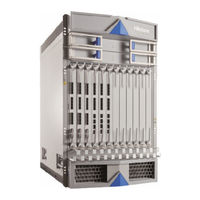
SG-6000-X10800
User Manuals: Hillstone SG-6000-X10800 Firewall
Manuals and User Guides for Hillstone SG-6000-X10800 Firewall. We have
3
Hillstone SG-6000-X10800 Firewall manuals available for free PDF download: Hardware Reference Manual, Reference Manual
Hillstone SG-6000-X10800 Hardware Reference Manual (233 pages)
Brand:
Hillstone
| Category:
Network Hardware
| Size: 26 MB
Table of Contents
Table of Contents
3
About this Manual
16
Contents
16
Document Conventions
16
Preface
16
Chapter 1 Product Profile
17
Expansion Module Introduction
18
System Control Module (SCM)
18
HA Function with Two Scms
18
Security Service Module (SSM)
19
Qos Service Module (QSM)
19
I/O Module (IOM)
20
Service and IO Module (SIOM)
20
Switch Module(SWM)
20
Configuring an Interface Module
21
Bypass Module
21
Bypassing the Device with a Bypass Module
21
Expansion Modules Compatible with SG-6000 X Series
22
Sg-6000-X10800
24
Hardware Parameters
26
Front Panel
26
Back Panel
28
Expansion Modules
29
CLR Button
31
Iom-P100-300
33
Iom-P40-300
34
Siom-P40-300
35
Siom-P100-300
36
Siom-P100D-300
37
LED Indicators
39
Power Supply Module
42
Power Module Diagram
43
Cooling System
44
Port Attributes
46
Sg-6000-X9180
46
Hardware Parameters
47
Front Panel
48
Back Panel
49
Expansion Modules
50
CLR Button
52
Iom-P100-300
54
Iom-P40-300
55
Siom-P40-300
57
Siom-P100-300
58
Siom-P100D-300
59
Instructions for Using SSM/IOM/QSM/SIOM
61
LED Indicators
61
Power Supply Module
64
Power Module Diagram
65
Cooling System
66
Port Attributes
68
Sg-6000-X8180
68
Hardware Parameters
69
Front Panel
70
Back Panel
71
Expansion Modules
71
CLR Button
73
Scm-D1T-260
73
Scm-D2T-260
75
Siom-P100-260
76
Siom-P100H-260
77
Iom-8Mm
78
Instructions for Using IOM-8MM
79
Monitor the Status of Ports
80
Forced Bypass
80
LED Indicators
80
Power Supply Module
83
Power Module Diagram
85
Cooling System
86
Port Attributes
87
Sg-6000-X7180
87
Hardware Parameters
88
Front Panel
89
CLR Button
90
Back Panel
91
Expansion Modules
92
Iom-16Sfp-100
97
Iom-4Xfp-100
98
Iom-2Q8Sfp+-200
99
Iom-2Q8Sfp
100
Iom-8Sfp
101
Iom-2Sm-Be/Iom-2Mm-Be
102
SWAP Pinhole
103
LED Indicators
103
Power Supply Module
107
Power Module Diagram
109
SD Card Slot
110
Cooling System
111
Port Attributes
112
Ports of the SG-6000 X Series
112
Console Port
115
Auxiliary Port (aux Port)
116
USB Port
116
Copper Port
117
SFP Port
117
1GE(SFP) Transceiver Module
118
1GE(SFP) Copper SFP Module
119
SFP+ Port
120
10GE(SFP+) Transceiver Module
121
XFP Port
123
10GE(XFP) Transceiver Module
124
QSFP+ Port
125
40GE(QSFP+) Transceiver Module
126
QSFP28 Port
127
100GE(QSFP28) Transceiver Module
128
Optical Ports Features: Interoperability, Backward, Compatibility, and Copper SFP Com
130
Patibility
130
Interoperability
130
Backward Compatibility
131
Copper SFP Compatibility
131
Chapter 2 Installation Preparations
133
Introduction
133
Installation Site Environment Requirements
133
Temperature/Humidity Requirements
133
Clearness Requirements
134
ESD Prevention
134
EMI Prevention
134
Grounding Requirements
135
Cabinet Requirements
135
Cabinet Size and Clearance Requirements
135
Cabinet Airflow Requirements
135
Rack Requirements
136
Rack Size and Strength
136
Rack Clearance Requirement
136
Rack Mounting Requirements
137
Unpacking
137
Unpacking the Package of SG-6000-X10800
137
Unpacking the Package of SG-6000-X9180/X8180/X7180/X6180/X6150
144
Other Safety Recommendations
147
Verifying the Parts Received
147
Installation Devices/Tools/Cables
147
Chapter 3 Installation
149
Overview
149
Safety Requirements
149
General Safety Warnings
150
Preventing ESD Damage
150
Fire Safety Requirements
154
Install Mounting Rail Assemblies
154
Installing the Device in a Rack
156
Tools Required
156
Before Installation
156
Installing SG-6000-X10800
157
Installing SG-6000-X9180
159
Installing SG-6000-X8180
161
Installing SG-6000-X7180
163
Installing the Device Using a Lift
163
Installing the Device Without a Lift
165
Installing Expansion Modules
166
Installing Expansion Modules of SG-6000-X10800
166
Tools Required
166
Installing an SCM/SWM
167
Installing an Ssm/Iom/Siom/Qsm/Bypass
168
Installing Expansion Modules of SG-6000-X9180
170
Tools Required
170
Installing an SCM/SWM
170
Installing an Ssm/Iom/Siom/Qsm/Bypass
171
Installing Expansion Modules of SG-6000-X8180
173
Tools Required
173
Installing an SCM
173
Installing an SIOM
174
Installing Expansion Modules of SG-6000-X7180
175
Tools Required
176
Installing an SSM
177
Installing a QSM
178
Installing an IOM
179
Installing a Bypass Module
181
Installing a Power Module
181
Tools Required
182
Installing an AC/DC Power Module of SG-6000-X10800/X9180
182
Installing an AC/DC Power Module of SG-6000-X8180
183
Installing a Power Module of SG-6000-X7180
184
Installing an AC Power Module
184
Installing a DC Power Module
185
Connecting Cables
186
Grounding the Chassis
186
Grounding the Chassis of SG-6000-X10800/X9180/X7180
186
Grounding the Chassis of SG-6000-X8180
187
Connecting the Console Cable
189
Connecting the Ethernet/Optical Cable
189
Connecting the Ethernet Copper Cable
189
Connecting the Ethernet Fiber Cable
190
Connecting an AC Power Cable
191
Connecting a DC Power Cable
192
Connecting the DC Power Cable of SG-6000-X10800/X9180
192
Connecting the DC Power Cable of SG-6000-X8180
193
Connecting the DC Power Cable of SG-6000-X7180
194
Powering On/Off the Device
195
Powering On/Off SG-6000-X10800/X9180
195
Powering On/Off SG-6000-X8180
195
Powering On/Off SG-6000-X7180
196
Verification after Installation
196
Chapter 4 Boot and Configuration
197
Introduction
197
Establishing a Configuration Environment
197
Console (CON) Connection
197
Webui
199
Telnet or SSH
199
Basic Configuration
199
Chapter 5 Hardware Maintenance and Replacement
201
Overview
201
General Maintenance
201
Tools Required
201
Replacing a Power Module
202
Replacing an AC Power Module
202
Replacing a DC Power Module
203
Replacing an Expansion Module
203
Replacing an Expansion Module of SG-6000-X10800
203
Replacing an SCM/SWM
203
Replacing an Ssm/Iom/Siom/Qsm/Bypass
204
Replacing an Expansion Module of SG-6000-X9180
206
Replacing an SCM/SWM
206
Replacing an Ssm/Iom/Siom/Qsm/Bypass
207
Replacing an Expansion Module of SG-6000-X8180
208
Replacing an SCM
208
Replacing an SIOM
209
Replacing an Expansion Module of SG-6000-X7180
210
Replacing an SCM
210
Replacing an SSM
210
Replacing a QSM
211
Replacing an IOM
212
Replacing a Bypass Module
213
Replacing the Cooling System Components
214
Replacing a Fan Tray
215
Replacing a Fan Tray of SG-6000-X10800
215
Replacing a Fan Tray of SG-6000-X9180
216
Replacing a Fan Tray on the Front Panel
216
Replacing a Fan Tray on the Back Panel
218
Replacing a Fan Tray of SG-6000-X8180
219
Replacing a Fan Tray of SG-6000-X7180
220
Replacing a Dustproof Net
221
Replacing a Dustproof Net of SG-6000-X10800
221
Replacing a Dustproof Net of SG-6000-X9180
224
Replacing a Dustproof Net of the Plastic Panel
224
Replacing a Dustproof Net of the Fan Tray
225
Replacing an Air Filter of SG-6000-X7180
226
Chapter 6 Troubleshooting
228
Introduction
228
Losing the Administrator Password
228
Troubleshooting Expansion Modules
228
Troubleshooting the Cooling System
229
Troubleshooting the Power System
229
Troubleshooting the Configuration System
229
Appendix: Supported Versions of Devices
230
Advertisement
Hillstone SG-6000-X10800 Reference Manual (173 pages)
Brand:
Hillstone
| Category:
Firewall
| Size: 24 MB
Table of Contents
Table of Contents
3
Preface
12
About this Manual
12
Document Conventions
12
Chapter 1 Product Profile
13
Contents
13
Device Chassis
13
Front Panel
17
Back Panel
20
LED Indicators
22
System Parameters
30
Overview
13
Expansion Modules
35
Scm
37
Ssm
39
Qsm
41
Iom
43
Siom
46
Swm
49
Bypass
50
Power Module
51
Instructions for Using SSM/IOM/QSM/SIOM
54
Ports
56
Console Port
56
Auxiliary Port
57
USB Port
57
Cooper Port
57
SFP Port
58
XFP Port
59
Qsfp+Port
60
SFP+ Port
62
QSFP28 Port
63
SD Card Slot
64
CLR Button
65
Cooling System
66
Chapter 2 Installation Preparations
72
Introduction
72
Installation Site Environment Requirements
72
Temperature/Humidity Requirements
72
Clearness Requirements
73
ESD Prevention
73
EMI Prevention
73
Grounding Requirements
74
Cabinet Requirements
74
Cabinet Size and Clearance Requirements
74
Cabinet Airflow Requirements
74
Rack Requirements
75
Rack Size and Strength
75
Rack Clearance Requirement
75
Rack Mounting Requirements
75
Unpacking
76
Unpacking the Package of SG-6000-X10800
76
Unpacking the Package of SG-6000-X9180/X8180/X7180/X6180/X6150
81
Other Safety Recommendations
86
Verifying the Parts Received
86
Installation Devices/Tools/Cables
86
Chapter 3 Installation
88
Overview
88
Safety Requirements
88
General Safety Warnings
89
Preventing ESD Damage
89
Fire Safety Requirements
93
Install Mounting Rail Assemblies
93
Installing the Device in a Rack
95
Tools Required
95
Before Installation
95
Installing SG-6000-X10800
96
Installing SG-6000-X9180
98
Installing SG-6000-X8180
100
Installing SG-6000-X7180
102
Installing the Device Using a Lift
102
Installing the Device Without a Lift
104
Installing Expansion Modules
105
Installing Expansion Modules of SG-6000-X10800
105
Tools Required
105
Installing an SCM/SWM
106
Installing an Ssm/Iom/Siom/Qsm/Bypass
107
Installing Expansion Modules of SG-6000-X9180
109
Installing an SCM/SWM
109
Tools Required
109
Installing an Ssm/Iom/Siom/Qsm/Bypass
110
Installing Expansion Modules of SG-6000-X8180
112
Installing an SCM
112
Tools Required
112
Installing an SIOM
113
Installing Expansion Modules of SG-6000-X7180
114
Tools Required
115
Installing an SSM
116
Installing a QSM
117
Installing an IOM
118
Installing a Bypass Module
120
Installing a Power Module
120
Tools Required
121
Installing an AC/DC Power Module of SG-6000-X10800/X9180
121
Installing an AC/DC Power Module of SG-6000-X8180
122
Installing a Power Module of SG-6000-X7180
123
Installing an AC Power Module
123
Installing a DC Power Module
124
Connecting Cables
125
Grounding the Chassis
125
Grounding the Chassis of SG-6000-X10800/X9180/X7180
125
Grounding the Chassis of SG-6000-X8180
126
Connecting the Console Cable
128
Connecting the Ethernet/Optical Cable
128
Connecting the Ethernet Copper Cable
128
Connecting the Ethernet Fiber Cable
129
Connecting an AC Power Cable
130
Connecting a DC Power Cable
131
Connecting the DC Power Cable of SG-6000-X10800/X9180
131
Connecting the DC Power Cable of SG-6000-X8180
132
Connecting the DC Power Cable of SG-6000-X7180
133
Powering On/Off the Device
133
Powering On/Off SG-6000-X10800/X9180
133
Powering On/Off SG-6000-X8180
134
Powering On/Off SG-6000-X7180
134
Verification after Installation
135
Chapter 4 Boot and Configuration
136
Introduction
136
Establishing a Configuration Environment
136
Console (CON) Connection
136
Webui
138
Telnet or SSH
138
Basic Configuration
138
Chapter 5 Hardware Maintenance and Replacement
140
Overview
140
General Maintenance
140
Tools Required
140
Replacing a Power Module
141
Replacing an AC Power Module
141
Replacing a DC Power Module
142
Replacing an Expansion Module
142
Replacing an Expansion Module of SG-6000-X10800
142
Replacing an SCM/SWM
142
Replacing an Ssm/Iom/Siom/Qsm/Bypass
143
Replacing an Expansion Module of SG-6000-X9180
145
Replacing an SCM/SWM
145
Replacing an Ssm/Iom/Siom/Qsm/Bypass
146
Replacing an Expansion Module of SG-6000-X8180
147
Replacing an SCM
147
Replacing an SIOM
148
Replacing an Expansion Module of SG-6000-X7180
149
Replacing an SCM
149
Replacing an SSM
149
Replacing a QSM
150
Replacing an IOM
151
Replacing a Bypass Module
152
Replacing the Cooling System Components
153
Replacing a Fan Tray
154
Replacing a Fan Tray of SG-6000-X10800
154
Replacing a Fan Tray of SG-6000-X9180
155
Replacing a Fan Tray on the Front Panel
155
Replacing a Fan Tray on the Back Panel
157
Replacing a Fan Tray of SG-6000-X8180
158
Replacing a Fan Tray of SG-6000-X7180
159
Replacing a Dustproof Net
160
Replacing a Dustproof Net of SG-6000-X10800
160
Replacing a Dustproof Net of SG-6000-X9180
163
Replacing a Dustproof Net of the Plastic Panel
163
Replacing a Dustproof Net of the Fan Tray
164
Replacing an Air Filter of SG-6000-X7180
165
Chapter 6 Troubleshooting
167
Introduction
167
Losing the Administrator Password
167
Troubleshooting Expansion Modules
167
Troubleshooting the Cooling System
168
Troubleshooting the Power System
168
Hillstone SG-6000-X10800 Hardware Reference Manual (89 pages)
SG-6000-X Series
Brand:
Hillstone
| Category:
Firewall
| Size: 7 MB
Table of Contents
Table of Contents
4
Chapter 1 Product Profile
10
Overview
10
Device Chassis
10
Figure 1-1: SG-6000-X7180 Chassis (Front View)
10
Front Panel
11
Figure 1-2: SG-6000-X7180 Chassis (Back View)
11
Figure 1-3: SG-6000-X10800 Front Panel
11
Back Panel
12
Figure 1-4: SG-6000-X7180 Front Panel
12
Table 1-1: SG-6000-X7180 Front Panel Description
12
Figure 1-5: SG-6000-X10800 Back Panel
13
LED Indicators
14
Figure 1-6: SG-6000-X7180 Back Panel
14
Table 1-2: SG-6000-X7180 Back Panel Description
14
Table 1-3: SG-6000-X10800 LED Indicators Description
15
Table 1-4: SG-6000-X7180 LED Indicators Description
16
System Parameters
17
Table 1-5: SG-6000-X10800/X7180 System Parameters
17
Expansion Modules
19
Scm
19
Figure 1-7: SCM-300
19
Ssm
20
Figure 1-8: SCM-100/SCM-20
20
Figure 1-9: SSM-300
20
Qsm
21
Figure 1-10: SSM-200
21
Figure 1-11: SSM-100
21
Figure 1-12: QSM-300
22
Figure 1-13: QSM-200
22
Figure 1-14: QSM-100
22
Iom
23
Figure 1-15: IOM-P40-300
23
Table 1-6: IOM Description
23
Figure 1-16: IOM-16SFP-100
24
Figure 1-17: IOM-4XFP-100
24
Figure 1-18: IOM-2Q8SFP+ -200
24
Swm
25
Figure 1-19: IOM-2Q8SFP
25
Figure 1-20: IOM-8SFP
25
Bypass Module
26
Figure 1-21:SWM-300
26
Figure 1-23: IOM-2SM-BE/ IOM-2MM-BM
26
Power Module
27
Figure 1-24: SG-6000-X10800 AC Power Module
27
Ports
28
Console Port
28
Figure 1-25: SG-6000-X10800 DC Power Module
28
Figure 1-26: SG-6000-X7180 AC Power Module
28
Figure 1-27: SG-6000-X7180 DC Power Module
28
Auxiliary Port
29
USB Port
29
SFP Port
29
Table 1-7: Console Port Attributes
29
Table 1-8: Auxiliary Port Attributes
29
Table 1-9: USB Port Attributes
29
XFP Port
30
Table 1-10: SFP Port Attributes
30
Table 1-11: SFP Optical Module Attributes
30
QSFP+ Port
31
Table 1-12: XFP Port Attributes
31
Table 1-13: XFP Optical Module Attributes
31
Table 1-14: QSFP+ Port Attributes
31
SFP+ Port
32
Table 1-15: QSFP+ Optical Module Attributes
32
Table 1-16: SFP+ Port Attributes
32
SD Card Slot
33
Table 1-17: SFP+ Optical Module Attributes
33
CLR Button
34
Cooling System
34
Figure 1-28: Fan Tray of SG-6000-X10800
35
Figure 1-29: Air Flow through the Chassis
35
Figure 1-30: Fan Tray
36
Figure 1-31: Air Flow through the Chassis
36
Chapter 2 Installation Preparation
37
Overview
37
Site Preparation
37
Temperature/Humidity Specifications
37
Cleanness Requirements
37
Table 2-1: Temperature/Humidity Specifications
37
ESD Prevention
38
EMI Prevention
38
Cabinet Requirements
38
Cabinet Size and Clearance Requirements
38
Table 2-2: Dust Concentration Requirements in the Equipment Room
38
Cabinet Airflow Requirements
39
Rack Requirements
39
Rack Size and Strength
39
Rack Clearance Requirements
39
Rack Mounting Requirements
39
Unpacking
39
Unpacking the Package of SG-6000-X10800
40
Figure 2-1: Position of Tongues to be Removed
40
Figure 2-2: Straightening the Tongue
41
Figure 2-3: Removing the Wooden Case
41
Figure 2-4: Removing the EPE
42
Unpacking the Package of SG-6000-X7180
43
Figure 2- 5: Removing the Screws
43
Verifying the Parts Received
44
Figure 2-6: Packages and Hardware Components
44
Chapter 3 Installation
45
Overview
45
Safety Requirements
45
General Safety Warnings
45
Preventing ESD Damage
46
Figure 3-1: ESD Point of SG-6000-X10800 on the Front Panel
47
Figure 3-2: ESD Point of SG-6000-X7180 on the Front Panel
47
Figure 3-3: ESD Point of SG-6000-X10800 on the Back Panel
48
Fire Safety Requirements
49
Installing the Device in a Rack
49
Tools Required
49
Figure 3-4: ESD Point of SG-6000-X7180 on the Back Panel
49
Before Installation
50
Installing SG-6000-X10800
50
Installing SG-6000-X7180
51
Figure 3-5: Installing the Device in a Rack
51
Figure 3-6: Installing Rack-Mounting Ears
52
Figure 3-7: Installing the Device in a Rack
53
Installing Expansion Modules
54
Installing Expansion Modules of SG-6000-X10800
54
Figure 3-8: Installing an SCM
55
Installing Expansion Modules of SG-6000-X7180
56
Figure 3-9: Installing an IOM
56
Figure 3-10: Installing an SCM
57
Figure 3-11: Installing an SSM (SSM-20)
58
Figure 3-12: Installing a QSM (QSM-20)
59
Figure 3-13: Installing an IOM (IOM-16SFP)
60
Installing a Power Module
61
Tools Required
61
Installing an AC/DC Power Module of SG-6000-X10800
61
Figure 3-14: Installing a Bypass Module
61
Installing an Power Module of SG-6000-X7180
62
Figure 3-15: Installing an AC Power Module
62
Figure 3-16: Installing an AC Power Module
63
Figure 3-17: Installing a DC Power Module
63
Connecting Cables
64
Tools Required
64
Grounding the Chassis
64
Figure 3-18: Grounding Screws
64
Connecting the Console Cable
65
Connecting the Ethernet/Optical Cable
65
Figure 3-19: Connecting the Ethernet Copper Cable
66
Connecting an AC Power Cable
67
Figure 3-20: Connecting the Ethernet Copper Cable
67
Figure 3-21: Connecting an AC Power Cable
67
Connecting a DC Power Cable
68
Powering On/Off the Device
69
Powering On/Off SG-6000-X10800
69
Powering On/Off SG-6000-X7180
69
Verification after Installation
70
Chapter 4 Boot and Configuration
71
Overview
71
Establishing a Configuration Environment
71
Console (CON) Connection
71
Figure 4-1: Console Port Configuration
71
Webui
72
Figure 4-2: Parameters for Terminal Session
72
Tenet and SSH
73
Basic Configuration
73
Chapter 5 Hardware Maintenance and Replacement
74
Overview
74
General Maintenance
74
Tools Required
74
Replacing a Power Module
74
Replacing an AC Power Module
75
Replacing a DC Power Module
75
Replacing an Expansion Module
75
Replacing an Expansion Module of SG-6000-X10800
75
Figure 5-1: Replacing an SCM
76
Figure 5-2: Replacing an IOM
77
Replacing an Expansion Module of SG-6000-X7180
78
Figure 5-3: Replacing an SCM
78
Figure 5-4: Replacing an SSM (SSM-20)
79
Figure 5-5: Replacing a QSM (QSM-20)
79
Figure 5-6: Replacing an IOM (IOM-16SFP)
80
Replacing the Cooling System Components
81
Replacing a Fan Tray
81
Figure 5-7: Replacing a Bypass Module
81
Figure 5-8: Removing a Fan Tray
82
Replacing an Air Filter
83
Figure 5-9: Removing a Fan Tray
83
Replacing a Dustproof Net
84
Figure 5-10: Replacing an Air Filter
84
Figure 5-11: Replacing the Air Inlet
85
Figure 5-12: Tightening the Screws
85
Figure 5-13: Taking out the Dustproof Net
86
Chapter 6 Troubleshooting
87
Overview
87
Losing the Administrator Password
87
Troubleshooting the Expansion Module
87
Troubleshooting the Cooling System
87
Troubleshooting the Power System
87
Troubleshooting the Configuration System
88
Copyright Information
89
Advertisement
Advertisement
Related Products
Hillstone SG-6000-X7180
Hillstone SG-6000-X5100
Hillstone SG-6000 X Series
Hillstone SG-6000-X9180
Hillstone SG6000-X8180
Hillstone SG-6000-E2860
Hillstone SG-6000-M2100
Hillstone SG-6000 E Series
Hillstone SG-6000-E1600
Hillstone SG-6000-E5660
Hillstone Categories
Firewall
Test Equipment
Network Hardware
Control Unit
Controller
More Hillstone Manuals
Login
Sign In
OR
Sign in with Facebook
Sign in with Google
Upload manual
Upload from disk
Upload from URL