Hillstone SG-6000-X7180 Hardware Reference Manual
Sg-6000-x series
Hide thumbs
Also See for SG-6000-X7180:
- Hardware reference manual (64 pages) ,
- Reference manual (173 pages) ,
- Hardware reference manual (233 pages)

Subscribe to Our Youtube Channel
Related Manuals for Hillstone SG-6000-X7180


Summary of Contents for Hillstone SG-6000-X7180
- Page 1 Hillstone StoneOS User Manual Hillstone SG-6000 X-Series Hardware Reference Guide www.hillstonenet.com TW-HW-XS-EN-V2.0-Y18M06...
- Page 2 Hillstone SG-6000 X-Series Hardware Reference Guide Name and Concentration of Toxic or Hazardous Substances and Elements in Products Toxic or hazardous substances and elements Component Lead Mercury Cadmium Cr6+ PDBE Metal parts Χ (including fasteners) Printed circuit board assemblies and Χ...
- Page 3 About This Manual Thanks for choosing the network security products from Hillstone Networks, Inc. This document is an installation manual for Hillstone SG-6000 X-Series device to help you install the Hillstone SG-6000 X-Series device properly. This manual includes the following chapters: ...
-
Page 4: Table Of Contents
Rack Size and Strength..................30 Rack Clearance Requirements................30 Rack Mounting Requirements ................30 Unpacking ........................ 30 Unpacking the Package of SG-6000-X10800 ............31 Unpacking the Package of SG-6000-X7180 .............. 34 Verifying the Parts Received .................. 35 Table of Contents Hillstone... - Page 5 Installing a Power Module ................... 52 Tools Required ..................... 52 Installing an AC/DC Power Module of SG-6000-X10800 ..........52 Installing an Power Module of SG-6000-X7180 ............53 Connecting Cables ..................... 55 Tools Required ..................... 55 Grounding the Chassis ..................55 Connecting the Console Cable................
- Page 6 Hillstone SG-6000 X-Series Hardware Reference Guide Replacing a Dustproof Net ..................75 Chapter 6 Troubleshooting ................... 78 Overview ........................78 Losing the Administrator Password ................78 Troubleshooting the Expansion Module ................. 78 Troubleshooting the Cooling System ................78 Troubleshooting the Power System ................78 Troubleshooting the Configuration System ..............
- Page 7 Figure 2-6: Packages and Hardware Components ............. 35 Figure 3-1: ESD Point of SG-6000-X10800 on the Front Panel ........38 Figure 3-2: ESD Point of SG-6000-X7180 on the Front Panel ........38 Figure 3-3: ESD Point of SG-6000-X10800 on the Back Panel ........39 Figure 3-4: ESD Point of SG-6000-X7180 on the Back Panel........
- Page 8 Hillstone SG-6000 X-Series Hardware Reference Guide Figure 3-8: Installing an SCM ................46 Figure 3-9: Installing an IOM ................. 47 Figure 3-10: Installing an SCM ................48 Figure 3-11: Installing an SSM (SSM-20) ..............49 Figure 3-12: Installing a QSM (QSM-20) ..............50 Figure 3-13: Installing an IOM (IOM-16SFP) ............
- Page 9 Hillstone SG-6000 X-Series Hardware Reference Guide List of Tables Table 1-1: SG-6000-X7180 Front Panel Description ............ 3 Table 1-2: SG-6000-X7180 Back Panel Description ............ 5 Table 1-3: SG-6000-X10800 LED Indicators Description ..........6 Table 1-4: SG-6000-X7180 LED Indicators Description ..........7 Table 1-5: SG-6000-X10800/X7180 System Parameters ..........
-
Page 10: Chapter 1 Product Profile
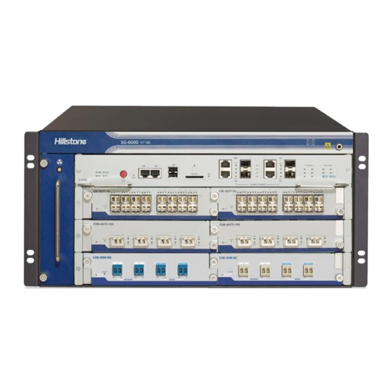
The chassis measures 18U. The Width x Depth x Height is 442.0mm x 715.0mmx 797.0mm, and the depth doesn’t include the depth of lever. Hillstone SG-6000-X7180 chassis is a standard 19-inch chassis that can be installed in one standard cabinet/rack if the cabinet/rack can handle the total weight of all hardware components. -
Page 11: Front Panel
Hillstone SG-6000 X-Series Hardware Reference Guide Figure 1-2: SG-6000-X7180 Chassis (Back View) Front Panel Hillstone SG-6000-X10800 front panel consists of twelve general expansion slots , two fan trays, cable rack, air inlet, rack-mounting ears, ESD point and several LED indicators. -
Page 12: Back Panel
Hillstone SG-6000 X-Series Hardware Reference Guide Hillstone SG-6000-X7180 front panel consists of one power switch button, one MGT port, three HA ports, two USB ports, one SD slot, one Console port, one Auxiliary port, one CLR button, six general expansion slots, one fan tray and several LED indicators. -
Page 13: Figure 1-5: Sg-6000-X10800 Back Panel
Hillstone SG-6000 X-Series Hardware Reference Guide Figure 1-5: SG-6000-X10800 Back Panel SG-6000-X7180 back panel consists of four power supply slots, four general expansion slots, two SCM slots, one fan tray and grounding screws. Chapter 1 Product Profile Hillstone... -
Page 14: Led Indicators
Hillstone SG-6000 X-Series Hardware Reference Guide Figure 1-6: SG-6000-X7180 Back Panel Table 1-2: SG-6000-X7180 Back Panel Description Label & Label & Label & Description Description Description Slot7 - Slot10: PS0 - PS3: Power General expansion Fan1 LED supply slots slots... -
Page 15: Table 1-3: Sg-6000-X10800 Led Indicators Description
Hillstone SG-6000 X-Series Hardware Reference Guide Table 1-3: SG-6000-X10800 LED Indicators Description Color/Status Description Green/Always on The device power is running normally. Orange/Always on The device power is running abnormally. Red/Always on Power failure so the system is down. The device is powered off. -
Page 16: Table 1-4: Sg-6000-X7180 Led Indicators Description
Hillstone SG-6000 X-Series Hardware Reference Guide module) The expansion module has failed to boot or has an Red/Always on error. Table 1-4: SG-6000-X7180 LED Indicators Description Color/Status Description Green/Always on The device power is running normally. Orange/Always on The device power is running abnormally. -
Page 17: System Parameters
Hillstone SG-6000 X-Series Hardware Reference Guide SCM in the slot SC0 serves as the backup module Orange/Blinking and is working normally. Red/Always on SCM in the slot SC0 has an error. SCM in the slot SC1 serves as the master module Green/Blinking and is working normally. - Page 18 Hillstone SG-6000 X-Series Hardware Reference Guide Item Description DDR2 SCM-100: 8GB SSM-100:32GB QSM-100: 16GB IOM-16SFP-100: 8GB DDR3 IOM-4XFP-100: 16GB SDRAM IOM-2Q8SFP+: 64GB IOM-8SFP+: 32GB SCM-300: 32GB SSM-200: 128GB QSM-200: 64GB IOM-2Q8SFP+ -200: 64GB DDR4 SSM-300: 128GB IOM-P40-300: 32GB QSM-300: 128GB...
-
Page 19: Expansion Modules
For detailed description of expansion modules, see Hillstone SG-6000 X- Series Expansion Modules Reference Guide. Note: A normal functioning SG-6000-X7180 requires at least one SCM, one SSM, one IOM and two power modules. A normal functioning SG-6000-X10800 requires at least one SCM, one SSM, one IOM, one SWM, three power modules and two fan trays. -
Page 20: Ssm
QoS. You must install at least one SSM in the device and can install more to escalate system performance. SSMs should be installed in the general expansion slots. SG-6000-X10800 uses the SSM model of SSM-300. SG-6000-X7180 uses the SSM model of SSM-200 and SSM-100. Figure 1-9: SSM-300... -
Page 21: Qsm
Service (QoS) processing. Without QSM, the device cannot process QoS. You can install one or more QSMs in general expansion slots. SG-6000-X10800 uses the QSM model of QSM-300. SG-6000-X7180 uses the QSM model of QSM-200 and QSM-100. Chapter 1 Product Profile... -
Page 22: Figure 1-12: Qsm-300
Hillstone SG-6000 X-Series Hardware Reference Guide Figure 1-12: QSM-300 Figure 1-13: QSM-200 Figure 1-14: QSM-100 Chapter 1 Product Profile Hillstone... -
Page 23: Iom
Hillstone SG-6000 X-Series Hardware Reference Guide I/O Module (IOM) is a hardware platform card with ports to receive and transfer data to SSM, QSM or SWM (only SG-6000-X10800 supports) modules. You must install at least one IOM and can install more to increase port amount. IOM should be installed in general expansion slots, but the IOM-2Q8SFP+ and IOM-8SFP+ module cannot be installed in the Slot7 expansion slot. -
Page 24: Figure 1-16: Iom-16Sfp-100
Hillstone SG-6000 X-Series Hardware Reference Guide Figure 1-16: IOM-16SFP-100 Figure 1-17: IOM-4XFP-100 Figure 1-18: IOM-2Q8SFP+ -200 Chapter 1 Product Profile Hillstone... -
Page 25: Swm
Hillstone SG-6000 X-Series Hardware Reference Guide Figure 1-19: IOM-2Q8SFP+ Figure 1-20: IOM-8SFP+ Switch Module (SWM) is a hardware platform card that connects twelve expansion slots of the front panel to forward the data. Only SG-6000-X10800 supports SWM. You should install at least one SWM in the device. You can install a second SWM for redundancy. -
Page 26: Bypass Module
You can install bypass module(s) in general expansion slots. For more information about Bypass configuration, please refer to StoneOS User Manual. Hillstone bypass module has the following two types: Single-mode bypass module: IOM-2SM-BE Multi-mode bypass module: IOM-2MM-BM SG-6000-X7180 uses IOM-2SM-BE and IOM-2MM-BM modules. -
Page 27: Power Module
AC (or four -48V DC) power modules. Four power modules with a power of 650W can be installed in SG-6000-X7180. You must install two AC (or DC) power modules to power the device. If every slot of device are installed with expansion module, please install at least 3 AC (or DC) power modules. -
Page 28: Ports
Figure 1-25: SG-6000-X7180 AC Power Module Figure 1-26: SG-6000-X7180 DC Power Module Ports The ports available for Hillstone SG-6000-X series are Console port, Auxiliary port, USB port, SFP port , XFP port, QSFP+ port and SFP+ port. This section explains the attributes of each port. -
Page 29: Auxiliary Port
Connect the Con port to the serial port of a PC and run a Services terminal emulation program on the PC to configure the appliance. Transmission Console Cable Medium Auxiliary Port Hillstone SG-6000-X series provides an RS-232C asynchronous serial auxiliary port. Table 1-8: Auxiliary Port Attributes Attribute Description Connector RJ-45 Port Standard RS-232C... -
Page 30: Xfp Port
Caution: To avoid dust falling into the SFP socket, you should place a rubber dust cap (originally in the accessory box) over the SFP port. Hillstone SG-6000-X series supports SFP optical module, but not SFP copper module. If you want the device to connect to an Ethernet copper cable, you need to use a copper SFP transceiver (Copper SFP transceiver of type FCLF-8520-3 from Finisar is recommended). -
Page 31: Qsfp+ Port
Frame Format Ethernet_SNAP Negotiation Mode XFP optical module 10Gbps Hillstone SG-6000-X series supports the following types of XFP optical module. The optical modules are available with LC-type connectors and are all hot-swappable. Table 1-13: XFP Optical Module Attributes Description Short-haul... -
Page 32: Sfp+ Port
Hillstone SG-6000 X-Series Hardware Reference Guide Table 1-15: QSFP+ Optical Module Attributes Description Short-haul Short-haul Ultra-long Haul Attribute Multimode Optical Multimode Optical Single-mode Module (850nm) Module (850nm) Optical Module (1550nm) Connector 50/125μm 50/125μm multi- 9/125μm single- Fiber Type mode fiber... -
Page 33: Sd Card Slot
(originally in the accessory box) over the SFP+ port. SD Card Slot Hillstone SG-6000-X7180 has an SD card slot for SD storage card on the front panel. SD card stores the data of the Network Behavior Control log messages. The highest capacity for SD card on the device is 32GB. -
Page 34: Clr Button
The CLR button of SG-6000-X10800 is in the pinholes of two SCM modules, and the CLR button of SG-6000-X7180 is in the pinhole of the front panel. The CLR button is used to reset the appliance back to the factory default settings. You can restore access to the appliance with this button if the login password is lost. -
Page 35: Figure 1-28: Fan Tray Of Sg-6000-X10800
Figure 1-28: Air Flow through the Chassis Each fan tray of SG-6000-X7180 has six fans and an air filter. The fan trays are vertically located in the Fan0 slot of the front panel and Fan1 slot of the back panel. -
Page 36: Figure 1-30: Fan Tray
Hillstone SG-6000 X-Series Hardware Reference Guide Figure 1-29: Fan Tray From the front of the chassis, there is air intake on the left side of the device. Air is pushed from the left intake and then goes through the chassis cage. The air is exhausted out the right of the chassis. -
Page 37: Chapter 2 Installation Preparation
Rack requirements Unpacking the appliance Site Preparation Hillstone SG-6000-X series products must be installed in indoor place. You should follow the instructions in this section to ensure that your site is properly prepared for the device installation. Temperature/Humidity Specifications Table 2-1 specifies the environmental temperature and relative humidity required for the device. -
Page 38: Esd Prevention
Use electromagnetic shielding when necessary. Cabinet Requirements Hillstone SG-6000-X series products are designed to be installed in 19-inch standard cabinet. It can be placed in a 19-inch or larger enclosed cabinet. Cabinet Size and Clearance Requirements The minimum size that can accommodate the appliance is 19-inch sized cabinet. -
Page 39: Cabinet Airflow Requirements
Routes of all cables be arranged to minimize the blockage of airflow of the chassis. Rack Requirements Hillstone SG-6000-X series products are designed to be installed in a 19-inch rack (four-post). Rack Size and Strength The rack rails must be spaced widely enough to accommodate the chassis external dimensions: 442.0mm wide, 715.0mm (doesn’t include the depth of lever) deep and... -
Page 40: Unpacking The Package Of Sg-6000-X10800
Hillstone SG-6000 X-Series Hardware Reference Guide Unpacking the Package of SG-6000-X10800 SG-6000-X10800 is wrapped in the wooden case. The wooden case consists of wooden panels, steel edges, tongues and EPE. Besides the chassis, the wooden case also contains the accessory box. -
Page 41: Figure 2-2: Straightening The Tongue
Hillstone SG-6000 X-Series Hardware Reference Guide Figure 2-2: Straightening the Tongue 5. After all the tongues around the bottom are straightened, two people are required to lift up the wooden case and remove it. Figure 2-3: Removing the Wooden Case 6. -
Page 42: Figure 2-4: Removing The Epe
Hillstone SG-6000 X-Series Hardware Reference Guide Figure 2-4: Removing the EPE 7. Remove baffles and take the device from the base. a. Use the cross screwdriver to remove the total ten screws on the vertical fixed baffles (as shown by number 1) on both sides. -
Page 43: Unpacking The Package Of Sg-6000-X7180
Warning: Do not discard the packing materials which can be used for repacking or transportation. Unpacking the Package of SG-6000-X7180 SG-6000-X7180 is wrapped in antistatic bags and shipped in cardboard carton. Besides the chassis, the carton also contains two power modules and an accessory box. -
Page 44: Verifying The Parts Received
Verify the parts and items you received against the packing list. If any part is missing, contact a service representative. Hillstone provides different expansion modules and power modules in separate individual packages according to your order. Chapter 2 Installation Preparation... -
Page 45: Chapter 3 Installation
Hillstone SG-6000 X-Series Hardware Reference Guide Chapter 3 Installation Overview Before installation, prepare the site according to the requirements in Chapter 2 Installation Preparation, and use the procedures below to install the device. 1. Perform security check according to Safety Requirements. -
Page 46: Preventing Esd Damage
Hillstone SG-6000 X-Series Hardware Reference Guide Preventing ESD Damage The hardware components are sensitive to electric damages. Static voltages can be easily generated whenever you handle plastic or foam packing material or if you move components across plastic or carpets. Some components can be impaired by static voltages. -
Page 47: Figure 3-1: Esd Point Of Sg-6000-X10800 On The Front Panel
Hillstone SG-6000 X-Series Hardware Reference Guide Figure 3-1: ESD Point of SG-6000-X10800 on the Front Panel Figure 3-2: ESD Point of SG-6000-X7180 on the Front Panel Chapter 3 Installation Hillstone... -
Page 48: Figure 3-3: Esd Point Of Sg-6000-X10800 On The Back Panel
Hillstone SG-6000 X-Series Hardware Reference Guide Figure 3-3: ESD Point of SG-6000-X10800 on the Back Panel Chapter 3 Installation Hillstone... -
Page 49: Fire Safety Requirements
Hillstone SG-6000 X-Series Hardware Reference Guide Figure 3-4: ESD Point of SG-6000-X7180 on the Back Panel Avoid contact between the chassis and your clothing. ESD voltages from your clothes may harm the hardware components. When installing or removing the hardware components, always keep the component-side up on an ESD surface or in an antistatic bag. -
Page 50: Before Installation
Hillstone SG-6000 X-Series Hardware Reference Guide Before Installation Before you begin to install the device, verify the following: The installation site is prepared according to Site Preparation. The package materials have been removed. See Unpacking. You have read the specifications in the Safety Requirements. -
Page 51: Installing Sg-6000-X7180
Hillstone SG-6000 X-Series Hardware Reference Guide Figure 3-5: Installing the Device in a Rack 8. Verify the alignment of the screws. Make sure every two screw pairs are in the same horizontal line. 9. Reinstall all removed hardware components back to the proper locations. See... -
Page 52: Figure 3-6: Installing Rack-Mounting Ears
Hillstone SG-6000 X-Series Hardware Reference Guide 1. Make sure the rack is secured to the floor or to the structure of the building. The area around the installation site has sufficient space for air floor and maintenance operations. 2. Use rack-mounting ear to mark the positions of floating nuts on the front rack posts. -
Page 53: Figure 3-7: Installing The Device In A Rack
Hillstone SG-6000 X-Series Hardware Reference Guide Figure 3-7: Installing the Device in a Rack 7. Verify the installation. Make sure every two screw pairs are in the same horizontal line and the device is stably placed on the plate. Installing the Device without a Lift If you do not use a lift to install the device, you should remove all parts that can be removed from the chassis and re-install them when the chassis is properly positioned. -
Page 54: Installing Expansion Modules
Hillstone SG-6000 X-Series Hardware Reference Guide 9. Reinstall all removed hardware components back to the proper locations. See Installing Expansion Modules, Installing a Power Module Replacing the Cooling System Components. Note: Before powering on the device, all empty slots should be covered with blank plates. -
Page 55: Figure 3-8: Installing An Scm
Hillstone SG-6000 X-Series Hardware Reference Guide expansion slot. Rotate the levers to outside, and slide the expansion module straight into the slot along the guide rail. Figure 3-8: Installing an SCM 6. When the lever head is inserted into the expansion slot, you should rotate the levers to the front of the module and slide the SCM into the slot until you feel resistant. -
Page 56: Installing Expansion Modules Of Sg-6000-X7180
Hillstone SG-6000 X-Series Hardware Reference Guide 3. Identify the slot of IOM. 4. If the slot is covered with a blank plate, loose its screws with a cross screwdriver and remove the plate, see Replacing an Expansion Module. 5. Position the IOM so that its front side faces you. Make sure that the lever is on the left side and the IOM module is plain with the outside edge of the expansion slot. -
Page 57: Figure 3-10: Installing An Scm
Hillstone SG-6000 X-Series Hardware Reference Guide Installing an SCM Installing an SSM Installing an QSM Installing an IOM Tools Required The following tools are required to install an expansion module: Cross screwdriver ESD wrist strap Installing an SCM The device supports up to two SCMs. -
Page 58: Figure 3-11: Installing An Ssm (Ssm-20)
Hillstone SG-6000 X-Series Hardware Reference Guide Installing an SSM The device requires at least one SSM and it supports up to 10 SSMs. SSM is located in Slot1 to Slot10. The following section takes SSM-20 as an example to describe the installation of SSM. -
Page 59: Figure 3-12: Installing A Qsm (Qsm-20)
Hillstone SG-6000 X-Series Hardware Reference Guide 1. Wear an electrostatic discharge (ESD) strap around your bare wrist and connect the strap to an ESD point on the chassis. See Prevention. 2. Take QSM out of its antistatic bag. 3. Identify the slot of QSM. -
Page 60: Figure 3-13: Installing An Iom (Iom-16Sfp)
Installing a Bypass Module Hillstone SG-6000-X7180 supports two types of bypass module: single-mode bypass module (IOM-2SM-BE) and multi-mode bypass module (IOM-2MM-BE). The bypass module is installed in Slot1 to Slot10. -
Page 61: Installing A Power Module
Hillstone SG-6000 X-Series Hardware Reference Guide Figure 3-14: Installing a Bypass Module 6. Tighten the screws on the IOM with a cross screwdriver. Installing a Power Module This part describes how to install power modules. Both AC and DC power modules are supported. -
Page 62: Installing An Power Module Of Sg-6000-X7180
You can hear a click of the lock stuck in the chassis. Verify that the panel of the power module is plain with the chassis panel. Figure 3-15: Installing an AC Power Module Installing an Power Module of SG-6000-X7180 Installing an AC Power Module To install an AC power module, take the following steps: 5. -
Page 63: Figure 3-16: Installing An Ac Power Module
Hillstone SG-6000 X-Series Hardware Reference Guide 7. Face the back panel of the chassis. 8. Slide the power module straight into the slot until it is fully seated in the chassis slot. You can hear a click of the lock stuck in the chassis. Verify that the panel of the power module is plain with the chassis panel. -
Page 64: Connecting Cables
Hillstone SG-6000 X-Series Hardware Reference Guide Connecting Cables This part describes how to connect the grounding wire, power cable, Ethernet cable, optical cable and power cable. The following takes SG-6000-X7180 as an example to introduce how to connect cables. Tools Required The following tools are required: ... -
Page 65: Connecting The Console Cable
Hillstone SG-6000 X-Series Hardware Reference Guide 7. Arrange the grounding cable so that it does not block the hardware components and it does not drape where people might trip over. Connecting the Console Cable The device provides an RS-232C asynchronous serial console (CON) port, through which you can configure the appliance. -
Page 66: Figure 3-19: Connecting The Ethernet Copper Cable
Hillstone SG-6000 X-Series Hardware Reference Guide Figure 3-19: Connecting the Ethernet Copper Cable Connecting the Ethernet Fiber Cable Follow the guidelines below when connecting cables to the ports: Be careful not to connect the Ethernet port to the wrong ports. Read the label above the port carefully. -
Page 67: Connecting An Ac Power Cable
Hillstone SG-6000 X-Series Hardware Reference Guide Figure 3-20: Connecting the Ethernet Copper Cable Warning: Laser danger! To protect your eyes from radiation harm, do not stare into a cable connector connected to a laser. Connecting an AC Power Cable The AC power cable is shipped with the chassis. -
Page 68: Connecting A Dc Power Cable
Connecting the DC Power Cable of SG-6000-X7180 To power the appliance with DC power source, use DC power cables to connect the appliance and the external DC power source. Hillstone does not provide DC power cables. Warning: Before performing the procedure, ensure that the cable is not connected with any power source and make sure the cables will not be powered on during the process. -
Page 69: Powering On/Off The Device
Hillstone SG-6000 X-Series Hardware Reference Guide 2. Switch off the power source. 3. Ensure that the DC power module has been properly installed according to the Installing a DC Power Module. 4. If the terminal on the power supply module has a plastic cover, remove the cover and keep it. -
Page 70: Verification After Installation
Hillstone SG-6000 X-Series Hardware Reference Guide Verification after Installation Verify the following when you finish the installation: Make sure all the cables are properly connected. Verify that the chassis is grounded. The air inlet and outlet are not blocked and the surroundings have sufficient space for hot air dissipation. -
Page 71: Chapter 4 Boot And Configuration
Chapter 4 Boot and Configuration Overview This chapter describes how to perform initial system boot and basic configuration of Hillstone SG-6000-X series. The configuration uses PC as the console terminal. Establishing a Configuration Environment Hillstone SG-6000-X series supports both local and remote configuration. -
Page 72: Webui
3. Switch on the power supply, and the appliance initializes the system automatically. If the booting succeeds, the system will display the command line prompt login. Enter the default administrator name and password “hillstone” at the login and password prompts, press Enter. And now you are successfully logged in and accessing the CLI. -
Page 73: Tenet And Ssh
2. Launch a Web browser of the management PC, enter the URL http://192.168.1.1 in the address bar, and then press Enter. 3. Enter the default administrator name and password (hillstone/hillstone) in the Login and Password text boxes. 4. Select the language you want to use. -
Page 74: Chapter 5 Hardware Maintenance And Replacement
If you remove one power module from the device with only three power modules, system will not work normally. SG-6000-X7180 supports 2+2 power module redundancy. If you remove one power module out of the chassis which has three or four power modules, the system can still work. -
Page 75: Replacing An Ac Power Module
Hillstone SG-6000 X-Series Hardware Reference Guide Replacing an AC Power Module To replace an AC power module, take the following steps: 1. Unplug the AC power cable from the power supply source. 2. Wear an electrostatic discharge (ESD) strap around your bare wrist and connect the strap to an ESD point on the chassis. -
Page 76: Figure 5-1: Replacing An Scm
Hillstone SG-6000 X-Series Hardware Reference Guide Replacing an SCM/SWM The following takes SCM as an example to introduce how to install an SCM or SWM. To replace an SCM, take the following steps: 1. Wear an electrostatic discharge (ESD) strap around your bare wrist and connect the strap to an ESD point on the chassis. -
Page 77: Figure 5-2: Replacing An Iom
Hillstone SG-6000 X-Series Hardware Reference Guide avoid dust falling into the chassis. Replacing an SSM/IOM/QSM/Bypass The following takes IOM as an example to introduce how to install an SSM, IOM, QSM or Bypass. To replace an IOM, take the following steps: 1. -
Page 78: Replacing An Expansion Module Of Sg-6000-X7180
Hillstone SG-6000 X-Series Hardware Reference Guide Replacing an Expansion Module of SG-6000-X7180 Replacing an SCM To replace an SCM, take the following steps: 1. Wear an electrostatic discharge (ESD) strap around your bare wrist and connect the strap to an ESD point on the chassis. See Prevention. -
Page 79: Figure 5-4: Replacing An Ssm (Ssm-20)
Hillstone SG-6000 X-Series Hardware Reference Guide Figure 5-4: Replacing an SSM (SSM-20) 4. Put the removed module into an antistatic bag or on a flat antistatic table. 5. Install a replacement module (see Installing an SSM). Note: If you do not want to install a new module, apply a blank plate over the slot to avoid dust falling into the chassis. -
Page 80: Figure 5-6: Replacing An Iom (Iom-16Sfp)
Hillstone SG-6000 X-Series Hardware Reference Guide 5. Install a replacement module (see Installing a QSM). Note: If you do not want to install a new module, apply a blank plate over the slot to avoid dust falling into the chassis. -
Page 81: Replacing The Cooling System Components
The cooling system of SG-6000-X series consists of 2 fan trays. Each fan tray of SG-6000-X10800 has 5 fans, and each fan tray of SG-6000-X7180 has 6 fans and 1 air filter. When the ventilation is inadequate due to fan failure or air filter block, you need to change the fan tray or the air filer. -
Page 82: Figure 5-8: Removing A Fan Tray
You are suggested to buy a backup fan tray firstly before maintaining the cooling system. Replacing a Fan Tray of SG-6000-X7180 To replace a fan tray, take the following steps: 1. Wear an electrostatic discharge (ESD) strap around your bare wrist and connect the strap to an ESD point on the chassis. -
Page 83: Replacing An Air Filter
Replacing an Air Filter The air filter is inside the fan tray of SG-6000-X7180. To avoid system overheating, install the fan tray with a replacement air filter immediately after it is removed. To replace the air filter, take the following steps: 1. -
Page 84: Replacing A Dustproof Net
Hillstone SG-6000 X-Series Hardware Reference Guide Figure 5-10: Replacing an Air Filter 8. Lay the replacement air filter over the outer mesh properly. 9. Cover the air filter with the inner mesh and tighten the screws removed in Step 5 to secure the meshes and the air filter. -
Page 85: Figure 5-11: Replacing The Air Inlet
Hillstone SG-6000 X-Series Hardware Reference Guide Figure 5-11: Replacing the Air Inlet 3. Position the air inlet on the workbench so that the dustproof side faces you. Use a cross screwdriver to loosen four screws until they pop out. Figure 5-12: Tightening the Screws 4. -
Page 86: Figure 5-13: Taking Out The Dustproof Net
6. Use a cross screwdriver to tighten four screws of the dustproof net. Note: The dustproof net can be bought alone from Hillstone. You are suggested to back up a dustproof. When the dustproof which is in use need to be replaced, you can replace it by the backup one. -
Page 87: Chapter 6 Troubleshooting
Hillstone SG-6000 X-Series Hardware Reference Guide Chapter 6 Troubleshooting Overview This chapter provides solutions to some common problems of Hillstone SG-6000 X- Series devices. Losing the Administrator Password If you lose the administrator password, please contact your local sales representative or you can reset the system to restore its factory password. -
Page 88: Troubleshooting The Configuration System
Hillstone SG-6000 X-Series Hardware Reference Guide Make sure the power supply cable is connected correctly. Ensure that the voltage of the power source conforms to the required voltage. For the PWR LED information, see Indicators. Troubleshooting the Configuration System The Console configuration terminal shows system booting message when the appliance is powered on. -
Page 89: Copyright Information
Hillstone, Hillstone Networks logo, StoneOS, StoneManager, Hillstone PnPVPN, UTM Plus are trademarks of Hillstone Networks. All other trademarks or registered marks are the property of their respective owners. Hillstone Networks assumes no responsibility for any inaccuracies in this document. Hillstone Networks reserves the right to change, modify, transfer, or otherwise revise this publication without notice.
Need help?
Do you have a question about the SG-6000-X7180 and is the answer not in the manual?
Questions and answers