
Related Manuals for Hillstone SG-6000 X Series


Summary of Contents for Hillstone SG-6000 X Series
- Page 1 Hillstone SG-6000 X Series Hardware Reference Guide TechDocs | docs.hillstonenet.com...
- Page 2 About This Guide Thanks for choosing the network security products from Hillstone Networks. This document is an installation guide for Hillstone devices to help you install the Hill- stone device properly. For more information, refer to the documentation site: https://- docs.hillstonenet.com.cn...
-
Page 3: Table Of Contents
Contents Contents Preface About This Manual Document Conventions Chapter 1 Product Profile Overview Device Chassis Front Panel Back Panel LED Indicators System Parameters Expansion Modules SIOM Bypass TOC - 1... - Page 4 Power Module Instructions for Using SSM/IOM/QSM/SIOM Ports Console Port Auxiliary Port USB Port Cooper Port SFP Port XFP Port QSFP+Port SFP+ Port QSFP28 Port SD Card Slot CLR Button Cooling System Chapter 2 Installation Preparations Introduction Installation Site Environment Requirements Temperature/Humidity Requirements Clearness Requirements ESD Prevention...
- Page 5 EMI Prevention Grounding Requirements Cabinet Requirements Cabinet Size and Clearance Requirements Cabinet Airflow Requirements Rack Requirements Rack Size and Strength Rack Clearance Requirement Rack Mounting Requirements Unpacking Unpacking the Package of SG-6000-X10800 Unpacking the Package of SG-6000-X9180/X8180/X7180/X6180/X6150 Other Safety Recommendations Verifying the Parts Received Verifying the Parts Received Installation Devices/Tools/Cables...
- Page 6 Fire Safety Requirements Install Mounting Rail Assemblies Installing the Device in a Rack Tools Required Before Installation Installing SG-6000-X10800 Installing SG-6000-X9180 Installing SG-6000-X8180 Installing SG-6000-X7180 Installing the Device Using a Lift Installing the Device without a Lift Installing Expansion Modules Installing Expansion Modules of SG-6000-X10800 Tools Required Installing an SCM/SWM...
- Page 7 Tools Required Installing an SCM Installing an SIOM Installing Expansion Modules of SG-6000-X7180 Tools Required Installing an SSM Installing a QSM Installing an IOM Installing a Bypass Module Installing a Power Module Tools Required Installing an AC/DC Power Module of SG-6000-X10800/X9180 Installing an AC/DC Power Module of SG-6000-X8180 Installing a Power Module of SG-6000-X7180 Installing an AC Power Module...
- Page 8 Connecting the Ethernet/Optical Cable Connecting the Ethernet Copper Cable Connecting the Ethernet Fiber Cable Connecting an AC Power Cable Connecting a DC Power Cable Connecting the DC Power Cable of SG-6000-X10800/X9180 Connecting the DC Power Cable of SG-6000-X8180 Connecting the DC Power Cable of SG-6000-X7180 Powering on/off the Device Powering on/off SG-6000-X10800/X9180 Powering On/Off SG-6000-X8180...
- Page 9 Overview General Maintenance Tools Required Replacing a Power Module Replacing an AC Power Module Replacing a DC Power Module Replacing an Expansion Module Replacing an Expansion Module of SG-6000-X10800 Replacing an SCM/SWM Replacing an SSM/IOM/SIOM/QSM/Bypass Replacing an Expansion Module of SG-6000-X9180 Replacing an SCM/SWM Replacing an SSM/IOM/SIOM/QSM/Bypass Replacing an Expansion Module of SG-6000-X8180...
- Page 10 Replacing a Bypass Module Replacing the Cooling System Components Replacing a Fan Tray Replacing a Fan Tray of SG-6000-X10800 Replacing a Fan Tray of SG-6000-X9180 Replacing a Fan Tray on the Front Panel Replacing a Fan Tray on the Back Panel Replacing a Fan Tray of SG-6000-X8180 Replacing a Fan Tray of SG-6000-X7180 Replacing a Dustproof Net...
- Page 11 Troubleshooting the Configuration System Appendix: Supported Versions of Devices TOC - 9...
-
Page 12: Preface
Preface About This Manual Thanks for choosing the network security products from Hillstone Networks. This document is an installation manual for the Hillstone SG-6000 XA-Series device to help you install the device properly. This manual includes the following chapters: IntroductionIntroduction... -
Page 13: Contents
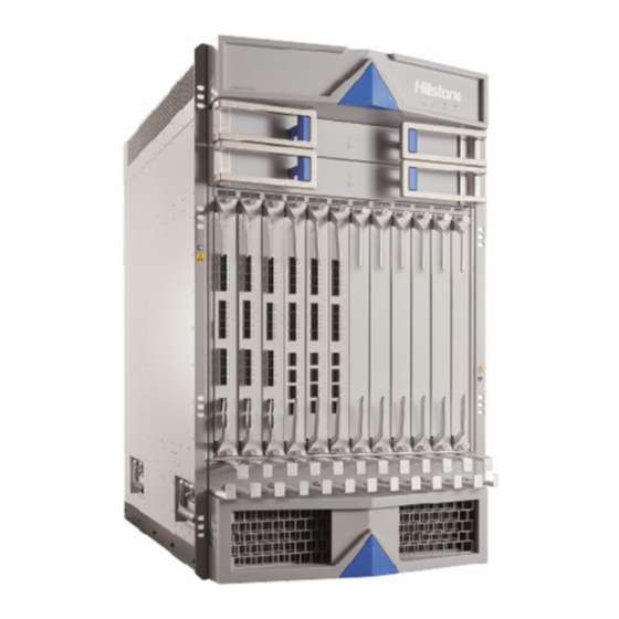
Devices. Device Chassis Hillstone SG-6000-X10800 chassis is a standard 19-inch chassis that can be installed in one stand- ard cabinet/rack if the cabinet/rack can handle the total weight of all hardware components. The chassis measures 18U. The Width x Depth x Height is 442.0mm x 715.0mmx 797.0mm, and the depth doesn't include the depth of lever. - Page 14 SG-6000-X10800 Chassis (Back View) is shown as below: Hillstone SG-6000-X9180 chassis is a standard 19-inch chassis that can be installed in one stand- ard cabinet/rack if the cabinet/rack can handle the total weight of all hardware components. The chassis measures 7U. The Width x Depth x Height is 440.0mm x 735.0mmx 308.0mm, which doesn't include the depth of handles on the front panel and the depth of lever on the back panel.
- Page 15 SG-6000-X9180 Chassis (Back View) is shown as below: Hillstone SG-6000-X8180 chassis is a standard 19-inch chassis that can be installed in one stand- ard cabinet/rack if the cabinet/rack can handle the total weight of all hardware components. The chassis measures 3U. The Width x Depth x Height is 440.0mm x 552.0mm x 132.2.0mm, which doesn't include the depth of handles on the front panel.
- Page 16 SG-6000-X8180 Chassis (Back View) is shown as below: Hillstone SG-6000-X7180 chassis is a standard 19-inch chassis that can be installed in one stand- ard cabinet/rack if the cabinet/rack can handle the total weight of all hardware components. The chassis measures 5U (440.0mm x 590.0mmx 225.0mm).
-
Page 17: Front Panel
Front Panel Hillstone SG-6000-X10800 front panel consists of twelve general expansion slots , two fan trays, two ESD points, one cable rack, one air inlet, two rack-mounting ears and several LED indicators. SG-6000-X10800 Front Panel is shown as below: Hillstone SG-6000-X9180 front panel consists of six general expansion slots , two handles, two rack-mounting ears, two air inlets, one fan tray, one cable rack, one ESD point and several LED indicators. - Page 18 Hillstone SG-6000-X8180 front panel consists of three general expansion slots , one air inlet, one ESD point and several LED indicators. SG-6000-X8180 Front Panel is shown as below: Hillstone SG-6000-X7180 front panel consists of one power switch button, one MGT port, three HA ports, two USB ports, one SD slot, one Console port, one Auxiliary port, one CLR button, six general expansion slots, one fan tray and several LED indicators.
- Page 19 SG-6000-X7180 Front Panel Description is shown as below: Label & Label & Label & Description Description Description STA: Status AUX: Aux- ESD: ESD point iliary port PWR: Power USB: USB Front Slots: Front port panel slot LED indic- ators ALM: Alarm SD Card: SD Rear Slots: Back card slot...
-
Page 20: Back Panel
Label & Label & Label & Description Description Description (HA ports) CON: Con- Slot1 - Slot6: sole port Slot status Back Panel SG-6000-X10800 back panel consists of eight power supply slots, two SCM slots, two SWM slots, one air outlet, one ESD point, one power switch, one CLR button and two grounding screws. - Page 21 SG-6000-X8180 back panel consists of two power supply slots, two SCM slots, four fan trays, and one grounding screw. SG-6000-X8180 Back Panel is shown as below: SG-6000-X7180 back panel consists of four power supply slots, four general expansion slots, two SCM slots, one fan tray and grounding screws.
-
Page 22: Led Indicators
SG-6000-X7180 Back Panel Description is shown as below: Label & Label & Label & Description Description Description PS0 - PS3: Slot7 - Fan1 LED Power supply Slot10: Gen- slots eral expan- sion slots Grounding ESD: ESD screws point SC0 - SC1: Fan1 tray SCM expan- sion slots... - Page 23 Color/Status Description Green/Always on The device power is running normally. Orange/Always on The device power is running abnormally. Red/Always on Power failure so the system is down. The device is powered off. Green/Always on The system is booting. Green/Blinking The system is running normally. Red/Always on The system has failed to boot or has an error.
- Page 24 Color/Status Description LED on Green/Always on The power module is working normally. the power Orange/Blinking The fan of power module or voltage output has supply failed. (PS0/PS1) Red/Always on The power module is inserted but using power-off protection. The power module is not correctly inserted. LED on Green/Always on The cooling system is working normally.
- Page 25 Color/Status Description Green/Always on The expansion module is booting. (expansion Green/Blinking The expansion module is running normally. module) Red/Always on The expansion module has failed to boot or has an error. SG-6000-X8180 LED Indicators Description is shown as below: Color/Status Description Green/Always on The device power is running normally.
- Page 26 Color/Status Description Green/Always on Not using HA, the device is the master device. Green/Blinking Two devices are in an HA cluster. This device is working as the master. Orange/Blinking Two devices are in an HA cluster. This device is working as the salve. Red/Blinking HA function has failed.
- Page 27 Color/Status Description Green/Always on The power of expansion module is running nor- (expansion mally. module) Orange/Always on The power of expansion module is running abnormally. Red/Always on Power failure so the expansion module is down. The expansion module is powered off. Green/Always on The expansion module is booting.
- Page 28 Color/Status Description Red/Always on The system is sending alarm(s). Green/Blinking The system is waiting. Orange/Blinking The system is using a trial license. Orange/Always on The trial license has expired and there is no legitimate license installed in the system. The system is running normally. Green/Always on Not using HA, the device is the master device.
- Page 29 Color/Status Description Orange/Blinking The port is sending or receiving data. No data is transmitted on this port. Front Green/Blinking The expansion module is working normally. Slots 1 - 6 Red/Always on The expansion module has an error. Orange/Blinking The expansion module is starting. Rear Slots Green/Blinking The expansion module is working normally.
-
Page 30: System Parameters
Color/Status Description Green/Always on The module is booting. (on the Green/Blinking The module is working normally. expansion Red/Always on The module has failed to start or has a con- module) nection error. The module is powered off or has been ejec- ted. - Page 31 Item Description 2 USB 2.0 Host ports 1 SD card slot 1 Console port (CON port) 1 Auxiliary port (AUX port) Expansion SG-6000-X10800 12 general expansion module slots Modules (SSM, IOM, SIOM and QSM mod- ules can be inserted) 2 SWM slots 2 SCM slots SG-6000-X9180 6 general expansion module slots...
- Page 32 Item Description SCM-300: 32GB SCM-280: 32GB DDR4 SSM-200: 128GB QSM-200: 64GB IOM-2Q8SFP+ -200: 64GB SSM-300: 128GB IOM-P40-300: 32GB SIOM-P100D-300: 32GB SIOM-P40-300: 64GB SIOM-P100-300: 64GB SIOM-P100-260: 96GB QSM-300: 64GB SCM-260/SCM-D1T-260/SCM- D2T-260: 8GB SG-6000-X8180 SCM-D1T-260:1T SCM-D2T-260:2T Flash SG-6000-X10800 SCM: 64GB Memory IOM: 8GB SIOM: 8GB SSM: 8GB QSM: 8GB...
- Page 33 Item Description SG-6000-X8180 SCM: 64GB SIOM: 16GB SG-6000-X7180 Host: 8GB SCM: 256MB SSM: 256MB IOM: 256MB QSM: 256MB Size SG-6000-X10800 442.0mm x 715.0mm (doesn't (W×D×H) include the depth of lever) x 797.0mm. SG-6000-X9180 440.0mm x 590.0mm (doesn't include the depth of handles on the front panel and levers on the back panel) x 225.0mm.
- Page 34 Item Description with product and its packaging) SG-6000-X8180 Net weight: 20.2kg (the fan trays are included) Gross weight: 30.3kg (total weight with product , its packaging, power modules and mounting rails) SG-6000-X7180 Net weight: 34.2kg (product alone) Gross weight: 54.0kg (total weight with product and its packaging) Power Rat- SG-6000-X10800...
-
Page 35: Expansion Modules
Expansion Modules Hillstone SG-6000-X series hardware modules include System Control Module (SCM), Security Service Module (SSM), QoS Service Module (QSM), I/O Module (IOM), Service and IO Module (SIOM), Switch Module (SWM) and Bypass module. For detailed description of expansion mod- ules, see Hillstone SG-6000 X-Series Expansion Modules Reference Guide. - Page 36 power modules, see Power Module). One SSM and one IOM modules One SIOM module Mixed use of the above two module usage schemes is not supported. For notes on the use of the SSM/IOM/QSM/SIOM modules, refer to Instruc- tions for Using SSM/IOM/SIOM. A normal functioning SG-6000-X9180 requires at least one SCM, one SSM, two fan trays, power modules (for the number of power modules, see Power Module) and one of following two module usage schemes:...
-
Page 37: Scm
ules and half width modules are different, see Installing Expansion Modules of SG-6000-X7180. System Control Module (SCM) is a hardware platform card that runs StoneOS to provide overall system management and control for the entire product. You must install at least one SCM in the device. You can install a second SCM for redundancy. SCM can only be installed in the SCM slots of the back panel. - Page 38 SCM-260/SCM-D1T-260/SCM-D2T-260 is shown as below: SCM-100/SCM-20 is shown as below: Chapter 1 Product Profile...
-
Page 39: Ssm
Security Service Module (SSM) is a hardware platform card which performs data processing other than QoS. You must install at least one SSM in the device and can install more to escalate system performance. SSMs should be installed in the general expansion slots. SG-6000-X10800 and SG-6000-X9180 use the SSM model of SSM-300. - Page 40 SSM-100/SSM-80 is shown as below: SSM-20 is shown as below: Chapter 1 Product Profile...
-
Page 41: Qsm
QoS Service Module (QSM) is a hardware platform card which solely performs Quality of Service (QoS) processing. Without QSM, the device cannot process QoS (Except for X7180, X8180, X9180 and X10800). SG-6000-X7180 can process QoS with IOM. SG-6000-X8180 can process QoS with SIOM. - Page 42 QSM-20 is shown as below: Notes: For SG-6000-X7180, when there is no QSM installed, you can install the IOM to process QoS (make sure that the device has installed iQoS license). In this case, the QoS doesn't support other traffic control modes but the poli- cing mode.
-
Page 43: Iom
For SG-6000-X9180 and SG-6000-X10800, when there is no QSM installed, you can install the IOM/SIOM to process QoS (make sure that the device has installed iQoS license). In this case, the QoS doesn't support other traffic control modes but the policing mode. For SG-6000-X7180, SG-6000-X8180, SG-6000-X9180 and SG-6000- X10800, when the device is installed with both QSM and IOM, QSM will take effect first for QoS. - Page 44 Model Type Product (10GE) IOM-16SFP-100 16 SPF ports (1GE) SG-6000-X7180 IOM-16SFP-80 SG-6000-X6180 IOM-16SFP SG-6000-X6150 IOM-4XFP-100 4 XFP ports (10GE) SG-6000-X7180 IOM-4XFP-80 SG-6000-X6180 IOM-4XFP SG-6000-X6150 IOM-2Q8SFP+ -200 2 QSFP+ ports SG-6000-X7180 (40GE) IOM-2Q8SFP+ 8 SFP+ ports (10GE) IOM-8SFP+ 8 SFP+ ports (10GE) IOM-P100-300 is shown as below: IOM-P40-300 is shown as below: Chapter 1 Product Profile...
- Page 45 IOM-16SFP-100 is shown as below: IOM-4XFP-100 is shown as below: Chapter 1 Product Profile...
-
Page 46: Siom
IOM-2Q8SFP+ -200 is shown as below: IOM-2Q8SFP+is shown as below: IOM-8SFP+ is shown as below: SIOM Service and IO Module (SIOM) is a hardware platform card with ports which provides following functions: Chapter 1 Product Profile... - Page 47 Receive data Fast forward data Transfer data and process data traffic You must install at least one SIOM and can install more to increase port amount. SIOM should be installed in general expansion slots. SIOM Description is shown as below: Model Type Product...
- Page 48 SIOM-P100-300 is shown as below: SIOM-P100-260 is shown as below: Chapter 1 Product Profile...
-
Page 49: Swm
SIOM-P40-300 is shown as below: Switch Module (SWM) is a hardware platform card that connects twelve expansion slots of the front panel to forward the data. Only SG-6000-X10800 and SG-6000-X9180 support SWM. You should install at least one SWM in the device. You can install a second SWM for redundancy. SWM can only be installed in the SWM slots of the back panel. -
Page 50: Bypass
You can install bypass module(s) in general expansion slots. For more information about Bypass configuration, please refer to StoneOS User Manual. Hillstone bypass module has the following two types: Chapter 1 Product Profile... -
Page 51: Power Module
Single-mode bypass module: IOM-2SM-BE Multi-mode bypass module: IOM-2MM-BE SG-6000-X7180 uses IOM-2SM-BE and IOM-2MM-BE modules. IOM-2SM-BE/IOM-2MM-BE is shown as below: Power Module Eight power modules can be installed in SG-6000-X10800. The power of 220V AC power mod- ule is 1600W (in the country or region where the standard voltage is 110V, the power is 800W) and the power of -48V DC power module is 1100W. - Page 52 one -48V DC power module to power the device. The installation of two power modules is recommended to ensure the redundant backup of the power modules. Four power modules with a power of 650W can be installed in SG-6000-X7180. You must install two AC (or DC) power modules to power the device.
- Page 53 SG-6000-X8180 AC Power Module is shown as below: SG-6000-X8180 DC Power Module is shown as below: Chapter 1 Product Profile...
-
Page 54: Instructions For Using Ssm/Iom/Qsm/Siom
SG-6000-X7180 AC Power Module is shown as below: SG-6000-X7180 DC Power Module is shown as below: Instructions for Using SSM/IOM/QSM/SIOM For SG-6000-X9180 and SG-6000-X10800, when using the SSM/IOM/QSM/SIOM modules, note the following matters: Notes: Mixed use of the SIOM module and the SSM/IOM/QSM modules is not supported. - Page 55 SIOM module) will cause network interruption. It is recommended that you call 1-800-889-9860 and start following module switches with the help of after-sales engineers from Hillstone Networks. For SG-6000-X9180 devices installed with the SSM module and the IOM module, if you want to switch to the SIOM module, you need to upgrade the device to StoneOS 5.5R6P9.9, remove the SSM module...
-
Page 56: Ports
SIOM module will not be recognized by the system. Ports The ports available for Hillstone SG-6000-X series are Console port, Auxiliary port, USB port, Cooper port, SFP port, XFP port, QSFP+ port, SFP+ port and QSFP28 port. This section explains the attributes of each port. -
Page 57: Auxiliary Port
Negotiation 1.1/2.0 autosensing Mode Cooper Port Hillstone SG-6000-X series supports cooper ports. The MGT port of SG-6000-X10800, SG- 6000-X9180 and SG-6000-X8180 is cooper port. Each combo port of SG-6000-X7180 includes one cooper port. Cooper Port Attributes is shown as below:... -
Page 58: Sfp Port
(originally in the accessory box) over the SFP port. Hillstone SG-6000-X series supports SFP optical module and SFP copper module. If you want the device to connect to an Ethernet copper cable, you need to use a copper SFP transceiver (Copper SFP transceiver of type FCLF-8520-3 from Finisar is recommended). -
Page 59: Xfp Port
SFP Optical Module Attributes is shown as below: Description Ultra-long Short-haul Medium-haul Long-haul Long-haul Haul Single- Attribute Multimode single-mode Single-mode Single-mode mode Optical Optical Mod- Optical Mod- Optical Mod- Optical Mod- Module ule (850nm) ule (1310nm) ule (1310nm) ule (1550nm) (1550nm) Connector Fiber Type... -
Page 60: Qsfp+Port
Hillstone SG-6000-X series supports the following types of XFP optical module. The optical modules are available with LC-type connectors and are all hot-swappable. XFP Optical Module Attributes is shown as below: Description Ultra-long Short-haul Short-haul Medium-haul Long-haul Haul Single- Attribute... - Page 61 Attribute Description Connector QSFP+ Frame Format Ethernet_II Ethernet_SNAP Negotiation QSFP+ optical module 40Gbps Mode The following types of QSFP+ optical module are supported. The optical modules are available with LC-type connectors and are all hot-swappable. QSFP+ Optical Module Attributes is shown as below: Description Short-haul Multimode Short-haul Multimode...
-
Page 62: Sfp+ Port
SFP+ Port IOM-2Q8SFP+ -200,IOM-2Q8SFP+ and IOM-8SFP+ provide eight SFP+ ports. IOM-P40-300 and SIOM-P40-300 provide twelve SFP+ ports. SIOM-P100D-300 provides twenty SFP+ ports. SIOM-P100-300 provides eight SFP+ ports. SIOM-P100-260 provides sixteen SFP+ ports. SFP+ Port Attributes is shown as below: Attribute Description Connector SFP+... -
Page 63: Qsfp28 Port
Description Ultra-long Short-haul Short-haul Medium-haul Long-haul Haul Single- Attribute Multimode Multimode Single-mode Single-mode mode Optical Optical Mod- Optical Mod- Optical Mod- Optical Mod- Module ule (850nm) ule (850nm) ule (1310nm) ule (1550nm) (1550nm) Distance (OM3) (OM1) Central 850nm 850nm 1310nm 1550nm 1550nm Wavelength... -
Page 64: Sd Card Slot
(originally in the accessory box) over the QSFP28 port. SD Card Slot Hillstone SG-6000-X7180 has an SD card slot for SD storage card on the front panel. SD card stores the data of the Network Behavior Control log messages. The highest capacity for SD card on the device is 32GB. -
Page 65: Clr Button
4. Push the SD card slightly and it will pop out. Notes: Hillstone recommends Kingston and SanDisk SD cards of 16GB and 32GB. To ensure the storage writing speed, the SD card should have a speed of Class 4 at least. -
Page 66: Cooling System
The cooling system of SG-6000-X8180 consists of four fan trays. The cooling system of other SG-6000 X series devices consist of two fan trays. Each fan tray of SG-6000-X10800 has five fans. The fan trays are horizontally located in the fan slots of the front panel. - Page 67 The air inlet is at the bottom of the front panel. Air is pushed from the air inlet and then goes through the chassis cage. The air is exhausted out the air outlet which is at the top of the rear panel and the side of the chassis.
- Page 68 Each fan tray of SG-6000-X9180 has ten fans. The fan trays are vertically located in the Fan0 of the front panel and Fan1 of the back panel. The fan trays can be replaced, see Replacing a Fan Tray of SG-6000-X9180 for more information.
- Page 69 The air inlet is on the top and right side of the front panel. Air is pushed from the air inlet and then goes through the chassis cage. The air is exhausted out the air outlet which is on the right side of the back panel.
- Page 70 Fan Tray of SG-6000-X8180 is shown as below: The air inlet is on the top of the front panel of the device and on the front panel of the expansion modules. Air is pushed from the air inlet and then goes through the chassis cage. The air is exhausted out the air outlet which is on the right side and the left side of the back panel.
- Page 71 Fan Tray is shown as below: From the front of the chassis, there is air intake on the left side of the device. Air is pushed from the left intake and then goes through the chassis cage. The air is exhausted out the right of the chassis.
-
Page 72: Chapter 2 Installation Preparations
Chapter 2 Installation Preparations Introduction This chapter introduces the preparations before installing the SG-6000 A-Seriesnew series NIPS device, including the installation site environment requirements, cabinet and rack requirements, and unpacking. This chapter includes the following sections: Installation site environment requirements Cabinet requirements Rack requirements Verifying the parts received... -
Page 73: Clearness Requirements
Clearness Requirements It is required that there are no explosive, conductive, magnetic, and corrosive dusts in the install- ation site. The dust concentration requirement in the equipment room is shown as below: Mechanically Active Sub- Unit Concentration stance Dust Particle Particles/m ≤3×10 (No visible dust on tables within 3... -
Page 74: Grounding Requirements
Keep the device away from radio stations, radar, and other high-frequency and high-current devices. Use electromagnetic shielding when necessary. Grounding Requirements To use the device more safely: Ensure that the grounding screw of the chassis is well grounded via the grounding cable. Ensure that the grounding pin of the power plug is well grounded. -
Page 75: Rack Requirements
Rack Requirements The SG-6000XAnew NIPS-Series device (except desktop models) can be installed in a 19-inch rack (four-post). Rack Size and Strength The rack rails must be spaced widely enough to accommodate the chassis's external dimensions: 440.0 mm high, 515.0 mm deep and 88.4 mm wide. Ensure the rack is strong enough to hold the weight of the fully configured device. -
Page 76: Unpacking
Unpacking This section provides guidelines for you to unpack the device before installation, including: Unpacking the appliance Verifying parts received Unpacking the Package of SG-6000-X10800 SG-6000-X10800 is wrapped in the wooden case. The wooden case consists of wooden panels, steel edges, tongues and EPE. Besides the chassis, the wooden case also contains the accessory box. - Page 77 3. There're many tongues in the wooden case. You are suggested to remove the tongues around the bottom of the wooden case. 4. Insert the straight screwdriver into the hole of the tongue from above, and then make the tongue level. Chapter 2 Installation Preparations...
- Page 78 Notes: The edges of tongue are sharp and may cause injury. 5. After all the tongues around the bottom are straightened, two people are required to lift up the wooden case and remove it. Chapter 2 Installation Preparations...
- Page 79 6. Take out the accessory box and EPE. Check the products received with the packing list. 7. Remove baffles and take the device from the base. a. Use the cross screwdriver to remove the total ten screws on the vertical fixed baffles (as shown by number 1) on both sides.
- Page 80 Chapter 2 Installation Preparations...
-
Page 81: Unpacking The Package Of Sg-6000-X9180/X8180/X7180/X6180/X6150
Notes: Do not discard the packing materials which can be used for repacking or transportation. Unpacking the Package of SG-6000-X9180/X8180/X7180/X6180/X6150 SG-6000-X8180 is wrapped in antistatic bags and EPE, and is shipped in cardboard carton. Besides the chassis, the carton also contains two power modules, an accessory box and a simple mounting rail assemblies. - Page 82 3. Cut the packing belts and remove the cover. 4. Take out the hardware components and accessory box, and then remove the foam. 5. Verify the parts received against the packing list. 6. Open the antistatic bag wrapping the chassis. Chapter 2 Installation Preparations...
- Page 83 Chapter 2 Installation Preparations...
- Page 84 Chapter 2 Installation Preparations...
- Page 85 Chapter 2 Installation Preparations...
-
Page 86: Other Safety Recommendations
When you receive the product, a packing list is included inside the accessory box. Verify the parts and items you received against the packing list. If any part is missing, contact a customer service representative. Hillstone provides different expansion modules and power supply modules in separate individual packages according to your order. Installation Devices/Tools/Cables... - Page 87 Terminal: Configuration terminal (e.g. an ordinary PC). Tools: Cross screwdriver and ESD wrist strap/antistatic gloves. Cables: Power cable, console cable and Ethernet cable. Chapter 2 Installation Preparations...
-
Page 88: Chapter 3 Installation
Chapter 3 Installation Overview Before installation, prepare the site according to the requirements in Chapter 2 Installation Pre- paration, and use the procedures below to install the device. 1. Perform security check according to Safety Requirements. 2. Install the simple mounting rail assemblies according to Installing Mounting Rail Assemblies. -
Page 89: General Safety Warnings
General Safety Warnings The following guidelines apply to any operational situations: Make sure only authorized personnel can perform operations to the device. Keep the area around the device free from dust, fire and humidity. Keep tools and accessories away from places where people might get tripped while walking. Do not wear loose clothes or jewelry, such as earrings and bracelets, as they might be caught in the chassis. - Page 90 ESD Point of SG-6000-X9180 on the Front Panel ESD Point of SG-6000-X8180 on the Front Panel Chapter 3 Installation...
- Page 91 ESD Point of SG-6000-X7180 on the Front Panel ESD Point of SG-6000-X10800 on the Back Panel Chapter 3 Installation...
- Page 92 ESD Point of SG-6000-X9180 on the Back Panel ESD Point of SG-6000-X7180 on the Back Panel Chapter 3 Installation...
-
Page 93: Fire Safety Requirements
Always use ESD wrist strap which should be directly contact with your skin. Notes: For safety, periodically check the resistance value of the ESD strap. The measurement should be in the range of 1 to 10 Mega ohms. Avoid contact between the chassis and your clothing. ESD voltages from your clothes may harm the hardware components. - Page 94 The mounting ears are used to fix the position of the chassis but cannot bear weight. The simple mounting rail assemblies shipped with the device are used to support the chassis if there is no tray on your rack. The mounting rail assemblies are used for 19-inch racks, with a height of 1U. 1.
-
Page 95: Installing The Device In A Rack
Installing the Device in a Rack This section describes how to install a device in a rack. A fully configured SG-6000-X10800 weighs approximately 194.0kg, a fully configured SG-6000-X9180 weighs approximately 93.1kg, a fully configured SG-6000-X8180 weighs approximately 36.5kg and a fully configured SG-6000- X7180 weighs approximately 53.0kg. -
Page 96: Installing Sg-6000-X10800
Make sure the rack or cabinet is secured to the floor and the site ventilation is adequate for heat dissipation and maintenance. Installing SG-6000-X10800 In order to install the device conveniently, you should remove all parts that can be removed from the chassis and re-install them when the chassis is properly positioned. - Page 97 7. Verify the alignment of the screws. Make sure every two screw pairs are in the same hori- zontal line. 8. Reinstall all removed hardware components back to the proper locations. See Installing Expansion Modules of SG-6000-X10800, Installing an AC/DC Power Module of SG-6000- X10800, and Replacing a Fan Tray of SG-6000-X10800.
-
Page 98: Installing Sg-6000-X9180
You should use the handles on the chassis side to remove the device to the rack or cabinet. To avoid damaging the chassis, you shouldn’t use the lever of modules to remove the device. Installing SG-6000-X9180 In order to install the device conveniently, you should remove all parts that can be removed from the chassis and re-install them when the chassis is properly positioned. - Page 99 7. Verify the alignment of the screws. Make sure every two screw pairs are in the same hori- zontal line. 8. Take the cable rack and screws out of the accessory box. Position the cable rack on the left rack-mounting ear, and use a cross screwdriver clockwise to tighten the screws. Chapter 3 Installation...
-
Page 100: Installing Sg-6000-X8180
9. Reinstall all removed hardware components back to the proper locations. See Installing Expansion Modules of SG-6000-X9180, Installing an AC/DC Power Module of SG-6000- X10800/X9180, and Replacing a Fan Tray of SG-6000-X9180. Notes: Before powering on the device, all empty slots should be covered with blank plates. - Page 101 3. Dismantle all the removable components, including power modules, all expansion modules (SCM and SIOM), blank plates and fan trays. For detailed steps of removing the com- ponents, see Chapter 5 Hardware Maintenance and Replacement. 4. Label all the removed parts so that you can reinstall them in the correct location. 5.
-
Page 102: Installing Sg-6000-X7180
Notes: Before powering on the device, all empty slots should be covered with blank plates. To prevent the equipment damage or personal injury, three people are needed to install the device. To avoid damaging the chassis, you should not use the lever of modules to remove the device. - Page 103 2. Use rack-mounting ear to mark the positions of floating nuts on the front rack posts. 3. Attach rack-mounting ears to the left and right side panels of the chassis respectively. 4. Load the chassis steadily on the center of the lift platform. 5.
-
Page 104: Installing The Device Without A Lift
7. Verify the installation. Make sure every two screw pairs are in the same horizontal line and the device is stably placed on the plate. Installing the Device without a Lift If you do not use a lift to install the device, you should remove all parts that can be removed from the chassis and re-install them when the chassis is properly positioned. -
Page 105: Installing Expansion Modules
5. Move the chassis in front of the rack. 6. With one person standing on each side, lift the chassis onto the tray of the rack or cabinet. 7. Use the screws to attach the left and right brackets to the rack. 8. -
Page 106: Installing An Scm/Swm
Cross screwdriver ESD wrist strap Installing an SCM/SWM SG-6000-X10800 supports up to two SCMs and two SWMs. SCM is located in the slot SCM0 and SCM1 of the back panel, and SWM is located in the slot SWM0 and SWM1 of the back panel. The following takes SCM as an example to introduce how to install an SCM or SWM. -
Page 107: Installing An Ssm/Iom/Siom/Qsm/Bypass
levers to outside, and slide the expansion module straight into the slot along the guide rail. 6. When the lever head is inserted into the expansion slot, you should rotate the levers to the front of the module and slide the SCM into the slot until you feel resistant. 7. - Page 108 1. Wear an electrostatic discharge (ESD) strap around your bare wrist and connect the strap to an ESD point on the chassis. See Prevention. 2. Take IOM out from its antistatic bag. 3. Identify the slot of IOM. 4. If the slot is covered with a blank plate, loose its screws with a cross screwdriver and remove the plate, see Replacing an Expansion Module.
-
Page 109: Installing Expansion Modules Of Sg-6000-X9180
8. To install more IOMs, repeat Step 3 to 7. Installing Expansion Modules of SG-6000-X9180 The device requires at least one SCM, one SSM, one IOM and one SWM. Additional expansion modules are added according to your needs. This part includes the following sections: Tools Required Installing an SCM/SWM Installing an SSM/IOM/SIOM/QSM/Bypass... -
Page 110: Installing An Ssm/Iom/Siom/Qsm/Bypass
4. If the slot is covered with a blank plate, loose its screws with a cross screwdriver and remove the plate, see Replacing an Expansion Module of SG-6000-X9180. 5. Position the SWM so that its front side faces you. Make sure that the lever is on the left side and the SWM module is plain with the outside edge of the expansion slot. - Page 111 1. Wear an electrostatic discharge (ESD) strap around your bare wrist and connect the strap to an ESD point on the chassis. See Prevention. 2. Take IOM out from its antistatic bag. 3. Identify the slot of IOM. 4. If the slot is covered with a blank plate, loose its screws with a cross screwdriver and remove the plate, see Replacing an Expansion Module of SG-6000-X9180.
-
Page 112: Installing Expansion Modules Of Sg-6000-X8180
Installing Expansion Modules of SG-6000-X8180 The device requires at least one SCM-260/SCM-D1T-260/SCM-D2T-260 and one SIOM-P100- 260. Additional expansion modules are added according to your needs. This part includes the following sections: Tools Required Installing an SCM Installing an SIOM Tools Required The following tools are required to install an expansion module: Cross screwdriver ESD wrist strap... -
Page 113: Installing An Siom
5. If the slot is covered with a blank plate, loose its screws with a cross screwdriver and remove the plate. 6. Position the SCM module so that its front side faces you. Make sure that the lever is on the left side and the SCM module is plain with the outside edge of the expansion slot. -
Page 114: Installing Expansion Modules Of Sg-6000-X7180
4. Face the front panel of the chassis, identify the slot in which the module should be installed. 5. If the slot is covered with a blank plate, loose its screws with a cross screwdriver and remove the plate, see Replacing an Expansion Module of SG-6000-X8180. -
Page 115: Tools Required
This part includes the following sections: Tools Required Installing an SCM Installing an SSM Installing a QSM Installing an IOM Installing a Bypass Module Tools Required The following tools are required to install an expansion module: Cross screwdriver ESD wrist strap Installing an SCM The device supports up to two SCMs. -
Page 116: Installing An Ssm
5. Position the SCM so that its front side faces you, and slide the SCM into the slot until you feel resistant, as shown below. 6. Tighten the screws on the SCM with a cross screwdriver. Installing an SSM The device requires at least one SSM and it supports up to 10 SSMs. SSM is located in Slot1 to Slot10. -
Page 117: Installing A Qsm
5. Position the SSM so that its front side faces you, and slide the SSM into the slot until you feel resistant, as shown below. 6. Tighten the screws on the SSM with a cross screwdriver. 7. To install more SSMs, repeat Step 2 to 6. Notes: When the modules are of half width, you can take the above steps to install them. -
Page 118: Installing An Iom
3. Identify the slot of QSM. 4. If the slot is covered with a blank plate, loose its screws with a cross screwdriver and remove the plate. 5. Position the QSM so that its front side faces you, and slide the QSM into the slot until you feel resistant, as shown below. - Page 119 1. Wear an electrostatic discharge (ESD) strap around your bare wrist and connect the strap to an ESD point on the chassis. See Prevention. 2. Take the IOM out of its antistatic bag. 3. Identify the slot of IOM. 4. If the slot is covered with a blank plate, loose its screws with a cross screwdriver and remove the plate.
-
Page 120: Installing A Bypass Module
Installing a Bypass Module Hillstone SG-6000-X7180 supports two types of bypass module: single-mode bypass module (IOM-2SM-BE) and multi-mode bypass module (IOM-2MM-BE). The bypass module is installed in Slot1 to Slot10. To install a bypass module, take the following steps: 1. Wear an electrostatic discharge (ESD) strap around your bare wrist and connect the strap to an ESD point on the chassis. -
Page 121: Tools Required
This part includes the following sections: Tools Required Installing an AC/DC Power Module of SG-6000-X10800/X9180 Installing an AC/DC Power Module of SG-6000-X8180 Installing a Power Module of SG-6000-X7180 Tools Required To install a power module, you need the tools: Cross screwdriver ESD wrist strap Installing an AC/DC Power Module of SG-6000-X10800/X9180 SG-6000-X10800 requires at least three (in the country or region where the standard voltage is... -
Page 122: Installing An Ac/Dc Power Module Of Sg-6000-X8180
click of the lock stuck in the chassis. Verify that the panel of the power module is plain with the chassis panel. Installing an AC/DC Power Module of SG-6000-X8180 SG-6000-X8180 requires at least one (in the country or region where the standard voltage is 110V, two are recommended) 220V AC power modules or one -48V DC power modules. -
Page 123: Installing A Power Module Of Sg-6000-X7180
1. Make sure the power module will not be powered during the installation process. 2. Wear an electrostatic discharge (ESD) strap around your bare wrist and connect the strap to an ESD point on the chassis. See Prevention. 3. Face the back panel of the chassis. 4. -
Page 124: Installing A Dc Power Module
3. Face the back panel of the chassis. 4. Slide the power module straight into the slot until it is fully seated in the chassis slot. You can hear a click of the lock stuck in the chassis. Verify that the panel of the power module is plain with the chassis panel. -
Page 125: Connecting Cables
plain with the chassis panel. Connecting Cables This part describes how to connect the grounding wire, power cable, Ethernet cable, optical cable and power cable. Tools Required Cross screwdriver ESD wrist strap Grounding the Chassis Grounding the Chassis of SG-6000-X10800/X9180/X7180 To avoid electrostatic discharge, you must correctly connect the chassis to the earth ground by a grounding wire. -
Page 126: Grounding The Chassis Of Sg-6000-X8180
To ground the chassis, take the following steps: 1. Wear an electrostatic discharge (ESD) strap around your bare wrist and connect the strap to an ESD point on the chassis. See Prevention. 2. Take the grounding cable out of the accessory box. 3. - Page 127 chassis. To ground the chassis of SG-6000-X8180, take the following steps: 1. Wear an electrostatic discharge (ESD) strap around your bare wrist and connect the strap to an ESD point on the chassis. See Prevention. 2. Take the grounding cable out of the accessory box. 3.
-
Page 128: Connecting The Console Cable
Connecting the Console Cable The SG-6000-X7180 device provides an RS-232C asynchronous serial console (CON) port, the expansion modules of SG-6000-X10800/X9180/X8180 provides an RS-232C asynchronous serial console (CON) port, through which you can configure the appliance. The console cable is an 8-core shielded cable, which has an RJ-45 connector that can be connected to the Console port of the appliance and a DB-9 (female) connector that can be connected to the serial port of a con- sole terminal. -
Page 129: Connecting The Ethernet Fiber Cable
Be careful not to connect the Ethernet port to the wrong ports. Read the label above the port carefully. For electrical Ethernet connection, use crossover cable or straight-through cable. Connecting the Ethernet Fiber Cable Follow the guidelines below when connecting cables to the ports: Be careful not to connect the Ethernet port to the wrong ports. -
Page 130: Connecting An Ac Power Cable
For XFP ports, QSFP+ ports, SFP+ ports or QSFP28 ports, insert the XFP, QSFP+, SFP+ or QSFP28 optical module into the corresponding port before connecting the MPO-type or LC-type connector to the module. Keep the followings in mind when connecting fiber cables: The curvature radius should be greater than 10cm. -
Page 131: Connecting A Dc Power Cable
To power the appliance with DC power source, use DC power cables to connect the appliance and the external DC power source. You will be provided with DC power cables when buying DC power modules from Hillstone. Notes: Before performing the procedure, ensure that the cable is not connected with any power source and make sure the cables will not be powered on during the process. -
Page 132: Connecting The Dc Power Cable Of Sg-6000-X8180
To power the appliance with DC power source, use DC power cables to connect the appliance and the external DC power source. Hillstone does not provide DC power cables. Notes: Before performing the procedure, ensure that the cable is not connected with any power source and make sure the cables will not be powered on during the process. -
Page 133: Connecting The Dc Power Cable Of Sg-6000-X7180
To power the appliance with DC power source, use DC power cables to connect the appliance and the external DC power source. Hillstone does not provide DC power cables. Notes: Before performing the procedure, ensure that the cable is not connected with any power source and make sure the cables will not be powered on during the process. -
Page 134: Powering On/Off Sg-6000-X8180
started. If the power cables are connected with the device respectively or the device is shut down manually, you should press the red button on the front panel. To power off the device, press the red button on the front panel for four seconds to shut down the device immediately. -
Page 135: Verification After Installation
Notes: The device requires at least two fan trays and one SCM to work normally. Verification after Installation Verify the following when you finish the installation: Make sure all the cables are properly connected. Verify that the chassis is grounded. The air inlet and outlet are not blocked and the surroundings have sufficient space for hot air dissipation. -
Page 136: Chapter 4 Boot And Configuration
Chapter 4 Boot and Configuration Introduction This chapter describes how to perform initial system boot and basic configuration of the Hillstone SG-6000XAnew NIPS-Series device, using a PC as the console terminal. Establishing a Configuration Environment The SG-6000 Xnew NIPS-Series device supports both local and remote configuration. Admin- istrators can use the following configuration methods. - Page 137 If the booting succeeds, the system will display the command line prompt "login". Enter the default administrator name and password "hillstone" at the "login" and "password" prompts, press Enter. And now you are successfully logged in and accessing the CLI.
-
Page 138: Webui
2. Launch a Web browser of the management PC, enter the URL https://192.168.1.1 in the address bar, and then press Enter. 3. Type the default administrator name (hillstone) and password (hillstone) into the text boxes respectively. 4. At the first sign of address, you need to read and accept the EULA (End User License Agree- ment). - Page 139 work security designs require different topology designs, working modes, security zones, and policy configurations. The basic configurations may include: Create security zones, including the link layer (L2) and network layer (L3). Bind different interfaces to correct security zones respectively. Assign IP addresses to interfaces. Configure the management functions of the interfaces and create the security policy rules.
-
Page 140: Chapter 5 Hardware Maintenance And Replacement
Chapter 5 Hardware Maintenance and Replacement Overview This chapter provides information on how to maintain and replace power module, expansion mod- ule and fan tray. General Maintenance For optimum performance, use the following routine maintenance procedures: Inspect the installation site for moisture, temperature and cleanness according to the Site Pre- paration. -
Page 141: Replacing A Power Module
Replacing a Power Module SG-6000-X10800 supports (3+1) x2 power module redundancy. If you remove one power mod- ule out of the chassis which has four or more power modules, the system can still work. If you remove one power module from the device with only three power modules, system will not work normally. -
Page 142: Replacing A Dc Power Module
Replacing a DC Power Module To replace a DC power module, take the following steps: Switch off the power source and remove the DC power cable from the power source. Wear an electrostatic discharge (ESD) strap around your bare wrist and connect the strap to an ESD point on the chassis. -
Page 143: Replacing An Ssm/Iom/Siom/Qsm/Bypass
2. Use a cross screwdriver to loosen SCM screws until they pop out. 3. Rotate the lever to outside till the lever head is out of the expansion slot. 4. Hold the module with one hand and pull it straight out of the expansion slot along the guide rail. - Page 144 1. Wear an electrostatic discharge (ESD) strap around your bare wrist and connect the strap to an ESD point on the chassis. See Prevention. 2. Use a cross screwdriver to loosen IOM screws until they pop out. 3. Rotate the lever to outside till the lever head is out of the expansion slot. 4.
-
Page 145: Replacing An Expansion Module Of Sg-6000-X9180
Replacing an Expansion Module of SG-6000-X9180 Replacing an SCM/SWM The following takes SWM as an example to introduce how to install an SCM or SWM. To replace an SWM, take the following steps: 1. Wear an electrostatic discharge (ESD) strap around your bare wrist and connect the strap to an ESD point on the chassis. -
Page 146: Replacing An Ssm/Iom/Siom/Qsm/Bypass
Notes: If you do not want to install a new module, apply a blank plate over the slot to avoid dust falling into the chassis. Replacing an SSM/IOM/SIOM/QSM/Bypass The following takes IOM as an example to introduce how to install an SSM, IOM, SIOM, QSM or Bypass. -
Page 147: Replacing An Expansion Module Of Sg-6000-X8180
Notes: If you do not want to install a new module, apply a blank plate over the slot to avoid dust falling into the chassis. Replacing an Expansion Module of SG-6000-X8180 Replacing an SCM To replace an SCM, take the following steps: 1. -
Page 148: Replacing An Siom
Replacing an SIOM To replace an SIOM, take the following steps: 1. Wear an electrostatic discharge (ESD) strap around your bare wrist and connect the strap to an ESD point on the chassis. See Prevention. 2. Use a cross screwdriver to loosen SIOM screws until they pop out. 3. -
Page 149: Replacing An Expansion Module Of Sg-6000-X7180
Replacing an Expansion Module of SG-6000-X7180 Replacing an SCM To replace an SCM, take the following steps: 1. Wear an electrostatic discharge (ESD) strap around your bare wrist and connect the strap to an ESD point on the chassis. See Prevention. -
Page 150: Replacing A Qsm
1. Wear an electrostatic discharge (ESD) strap around your bare wrist and connect the strap to an ESD point on the chassis. See Prevention. 2. Use a cross screwdriver to loosen SCM screws until they pop out. 3. Hold the screws and pull the SSM straight out of the chassis, as shown below. 4. -
Page 151: Replacing An Iom
3. Hold the screws and pull the QSM straight out of the chassis, as shown below. 4. Put the removed module into an antistatic bag or on a flat antistatic table. 5. Install a replacement module (see Installing a QSM). Notes: If you do not want to install a new module, apply a blank plate over the slot to avoid dust falling into the chassis. -
Page 152: Replacing A Bypass Module
4. Hold the screws and pull the IOM straight out of the chassis, as shown below. 5. Put the removed module into an antistatic bag or on a flat antistatic table. 6. Install a replacement module (see Installing an IOM). Notes: If you do not want to install a new module, apply a blank plate over the slot to avoid dust falling into the chassis. -
Page 153: Replacing The Cooling System Components
4. Hold the screws and pull the IOM straight out of the chassis, as shown below. 5. Put the removed module into an antistatic bag or on a flat antistatic table. 6. Install a replacement module (see Installing a Bypass Module). -
Page 154: Replacing A Fan Tray
When the fan tray cannot work normally or has been used for a year, you should change the fan tray. You can buy the fan tray alone from Hillstone. To prevent over-heating, you should install a replacement fan tray immediately after you remove the existing one. -
Page 155: Replacing A Fan Tray Of Sg-6000-X9180
4. Grasp the replacement fan tray with the correct direction of FAN logo. Make sure that the fan tray is plain with the outside edge of the fan slot. Press the unlocking button and slide the fan tray into the slot till you feel resistant. Notes: To prevent over-heating, you should install the replacement fan tray within one minute after the existing fan tray is removed. - Page 156 3. Hold the front panel, and slide the front panel to the right. Pull it out from the chassis. 4. Use a cross screwdriver to loosen three screws of the fan tray counter-clockwise until they pop out. 5. Hold the handle of the fan tray and pull it out a little to disconnect it to power. Wait till the fans stop spinning.
-
Page 157: Replacing A Fan Tray On The Back Panel
6. Grasp the replacement fan tray and make sure that the fan tray is plain with the outside edge of the fan slot. Slide the fan tray into the slot till you feel resistant. Use a cross screwdriver clockwise to tighten three screws of the fan tray. 7. -
Page 158: Replacing A Fan Tray Of Sg-6000-X8180
5. Grasp the replacement fan tray with the screws on the right side of your palm. Slide the fan tray into the slot until you feel resistant. 6. Use a cross screwdriver clockwise to tighten two screws on the fan tray. Notes: To prevent over-heating, you should install the replacement fan tray within one minute after the existing fan tray is removed. -
Page 159: Replacing A Fan Tray Of Sg-6000-X7180
5. Grasp the replacement fan tray with the screws on the bottom of your palm. Slide the fan tray into the slot until you feel resistant. 6. Tighten the screws on the fan tray. Notes: To prevent over-heating, you should install the replacement fan tray within one minute after the existing fan tray is removed. -
Page 160: Replacing A Dustproof Net
5. Grasp the replacement fan tray with the screws on the right side of your palm. Slide the fan tray into the slot until you feel resistant. 6. Tighten the screws on the fan tray. Notes: To prevent over-heating, you should install the replacement fan tray within one minute after the existing fan tray is removed. - Page 161 2. Hold the air inlet, and press the blue button on both sides of the air inlet. Then, pull it out from the chassis. Chapter 5 Hardware Maintenance and Replacement...
- Page 162 3. Position the air inlet on the workbench so that the dustproof side faces you. Use a cross screwdriver to loosen four screws until they pop out. 4. Take out the dustproof net from the air inlet. Chapter 5 Hardware Maintenance and Replacement...
-
Page 163: Replacing A Dustproof Net Of Sg-6000-X9180
5. Put the cleaned or new dustproof net into the air inlet. Hold the air inlet, and press the blue button on both sides of the air inlet. Make sure that the air inlet is plain with the outside edge of the slot. Slide the air inlet straight into the slot till it is fully seated in the chassis slot. -
Page 164: Replacing A Dustproof Net Of The Fan Tray
5. Put the new dustproof net into the front panel. Use a cross screwdriver to tighten three screws of the dustproof net. 6. Hold the front panel, and make sure that the two panel is plain with the outside edge of the slot. -
Page 165: Replacing An Air Filter Of Sg-6000-X7180
Notes: The dustproof net can be bought alone from Hillstone. You are suggested to back up the dustproof nets (including a dustproof net of the plastic panel and a dustproof net of the fan tray). When the dustproof net which is in use need to be replaced, you can replace it by the backup one. - Page 166 7. Take out the air filter, as shown below. 8. Lay the replacement air filter over the outer mesh properly. 9. Cover the air filter with the inner mesh and tighten the screws removed in Step 5 to secure the meshes and the air filter. 10.
-
Page 167: Chapter 6 Troubleshooting
Chapter 6 Troubleshooting Introduction This chapter provides solutions to some common problems of the Hillstone SG-6000 XAnew NIPS-Series device. Losing the Administrator Password If you lose the administrator password, please contact your local sales representative or you can reset the system to restore its factory password. -
Page 168: Troubleshooting The Cooling System
Troubleshooting the Cooling System The cooling system consists of fan trays and an anti-dust mesh.A malfunctioning fan/fan tray or dust-full anti-dust mesh can influence the ventilation through the chassis. When the system is over heated, it will shut itself down. When the cooling system malfunctions, take the following steps to troubleshoot: Use the command show environment to view the chassis temperature and fan spinning speed. - Page 169 Make sure the power supply is correctly connected and powered on. Verify the Console cable is connected properly. Ensure the terminal configuration settings are correct. If above steps reveal no error, the Console cable may be broken. Chapter 6 Troubleshooting...
- Page 170 Appendix: Supported Versions of Devices During the production process, components of part SG-6000 X series devices have been updated, which may cause the incompatibility among software versions. The table below displays the device of which the components have updated. Check whether your device is in the following table.
- Page 171 Whether the updated Whether Device SN Range IOM-2Q8SFP+- IOM- (Update devices 200/SSM- Device 2Q8SFP+- Device Supported Ver- to the supported 200/QSM-200 is Model 200/SSM- sions versions if SN is used(Produced after 200/QSM- within the range) the 20th week of 200 is Used 2018) Before 5.5R1P10 and later P ver-...
- Page 172 Whether the updated Whether Device SN Range IOM-2Q8SFP+- IOM- (Update devices 200/SSM- Device 2Q8SFP+- Device Supported Ver- to the supported 200/QSM-200 is Model 200/SSM- sions versions if SN is used(Produced after 200/QSM- within the range) the 20th week of 200 is Used 2018) sions 5.0R4P5.42 and later P...
- Page 173 Whether the updated Whether Device SN Range IOM-2Q8SFP+- IOM- (Update devices 200/SSM- Device 2Q8SFP+- Device Supported Ver- to the supported 200/QSM-200 is Model 200/SSM- sions versions if SN is used(Produced after 200/QSM- within the range) the 20th week of 200 is Used 2018) 5.5R6, 5.5R7) Appendix: Supported Versions of Devices...
Need help?
Do you have a question about the SG-6000 X Series and is the answer not in the manual?
Questions and answers