Sign In
Upload
Manuals
Brands
Fronius Manuals
Inverter
PRIMO GEN24 PLUS
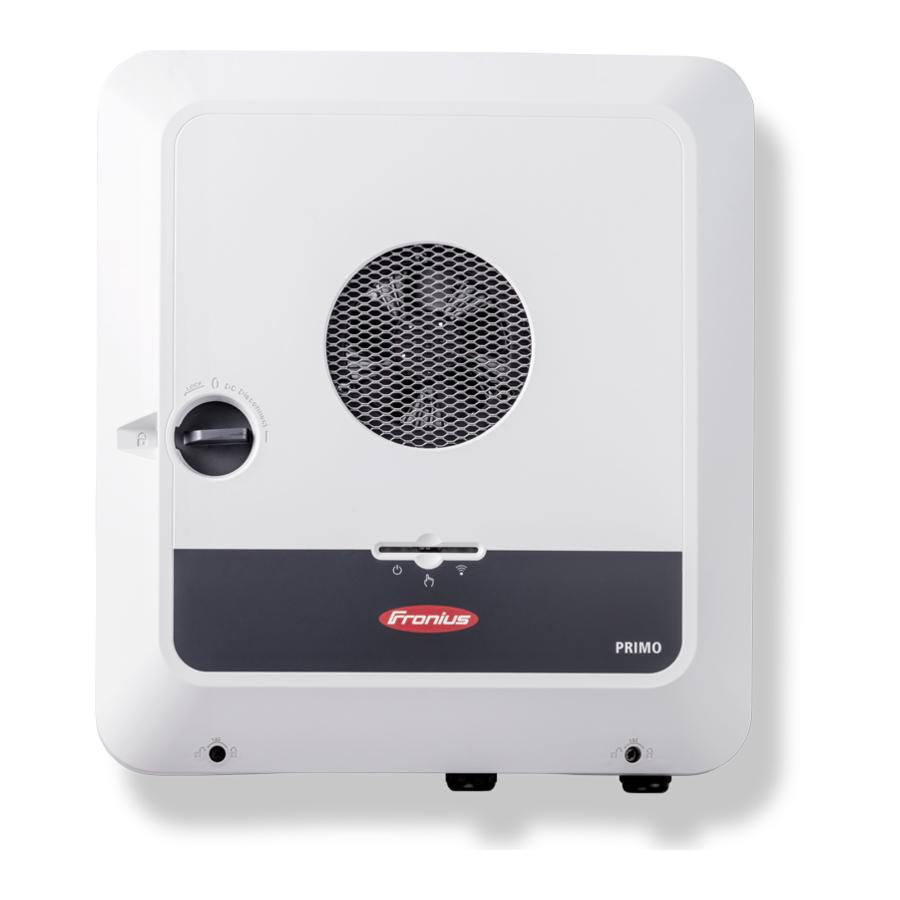
Fronius PRIMO GEN24 PLUS Manuals
Manuals and User Guides for Fronius PRIMO GEN24 PLUS. We have
10
Fronius PRIMO GEN24 PLUS manuals available for free PDF download: Operating Instructions Manual, Quick Start Manual
Fronius PRIMO GEN24 PLUS Operating Instructions Manual (208 pages)
Brand:
Fronius
| Category:
Inverter
| Size: 38 MB
Table of Contents
Table of Contents
3
Safety Rules
8
Explanation of Safety Notices
8
Safety
8
General
8
Environmental Conditions
9
Qualified Personnel
9
Noise Emission Values
9
EMC Measures
10
Backup Power
10
Data Protection
11
Copyright
11
Protective Earthing (PE)
11
General Information
13
Fronius Primo GEN24
15
Device Concept
15
Function Overview
15
Fronius up
16
Scope of Supply
16
Intended Use
16
Thermal Concept
17
Fronius Solar.web
17
Local Communication
18
The Various Operating Modes
19
Operating Modes - Explanation of Symbols
19
Operating Mode - Inverter with Battery
20
Operating Mode - Inverter with Battery and Several Smart Meters
20
Operating Mode - Inverter with Battery, AC-Coupled to Another Inverter
20
Operating Mode - Inverter with Battery and Backup Power Function
21
Operating Mode - Inverter with Battery, Ohmpilot and Backup Power Function
21
Operating Mode - Inverter with Battery, Further Inverter and Backup Power Function
21
Energy Flow Direction of the Inverter
22
Operating States (Only for Systems with a Battery)
22
Energy Saving Mode
24
General
24
Switch-Off Conditions
24
Switch-On Conditions
24
Special Case
24
Indication of Energy Saving Mode
25
Suitable Batteries
26
General
26
Limitations in Operation
26
BYD Battery-Box Premium
26
Lg Resu Flex
27
Manual System Start
29
Requirements
29
Notification of System Shutdown
29
Manual Battery Start after System Shutdown
29
Starting Backup Power Operation after a System Shutdown
29
Protection of People and Equipment
30
Central Grid and System Protection
30
WSD (Wired Shutdown)
30
Rcmu
30
Insulation Monitoring
30
AFCI - Arc Fault Circuit Interrupter (Arc Guard)
30
Safe State
31
Surge Protective Device
31
Control Elements and Connections
32
Connection Area
32
Connection Area Divider
33
Ground Electrode Terminal
33
DC Disconnector
34
Data Communication Area
34
Button Functions and LED Status Indicator
35
Internal Schematic Connection Diagram of the Ios
37
Backup Power Variant - PV Point (OP)
39
General
41
PV Point (OP)
41
Explanation - PV Point (OP)
41
Backup Power Variant - Full Backup
43
General
45
Prerequisites for Backup Power Mode
45
Transitioning from Feeding Energy into the Grid to Backup Power Mode
45
Transitioning from Backup Power Mode to Feeding Energy into the Grid
45
Backup Power and Energy Saving Mode
46
Automatic Switch to Backup Power Including Backup Power Circuits and 1-Pin Separation, E.g
47
Austria or Australia
47
Functions
47
Transitioning from Feeding Energy into the Grid to Backup Power Mode
47
Transitioning from Backup Power Mode to Feeding Energy into the Grid
47
Automatic Switch to Backup Power All-Pin Separation, E.g. Germany, France, UK, Spain
48
Functions
48
Transitioning from Feeding Energy into the Grid to Backup Power Mode
48
Transitioning from Backup Power Mode to Feeding Energy into the Grid
49
Automatic Switch to Backup Power All-Pin Separation, Italy
50
Functions
50
Transitioning from Feeding Energy into the Grid to Backup Power Mode
50
Transitioning from Backup Power Mode to Feeding Energy into the Grid
51
Functions
52
Transitioning from Feeding Energy into the Grid to Backup Power Mode
52
Transitioning from Backup Power Mode to Feeding Energy into the Grid
53
Installation
55
General
57
Quick-Lock System
57
Warning Notices on the Device
57
System Component Compatibility
59
Installation Location and Position
60
Choosing the Location of the Inverter
60
Choosing the Location of Third-Party Batteries
61
Installation Position of Inverter
62
Install the Mounting Bracket and Hang up the Inverter
64
Selecting the Fixing Material
64
Properties of the Mounting Bracket
64
Do Not Deform the Mounting Bracket
64
Fitting the Mounting Bracket to a Wall
64
Installing the Mounting Bracket on a Mast or Beam
65
Attaching the Mounting Bracket to Mounting Rails
66
Attaching the Inverter to the Mounting Bracket
66
Prerequisites for Connecting the Inverter
67
Different Cable Types
67
Permissible Cables for the Electrical Connection
67
Permissible Cables for the Data Communication Connection
68
Cross Section of the AC Cable
69
Cross Section of the DC Cable
69
Maximum Alternating Current Fuse Protection
69
Connecting the Inverter to the Public Grid (AC Side)
71
Safety
71
Connecting Solar Module Strings to the Inverter
74
General Comments Regarding PV Modules
74
Safety
74
Module Array - General Information
75
Module Array Configuration 8 - 10 Kw
75
Connecting the Solar Module Strings to the Inverter
76
Connecting the Battery to the Inverter
80
Safety
80
Connecting the Battery on the DC Side
80
Connecting the LG RESU FLEX Ground Conductor
84
Connecting Backup Power - PV Point (OP)
85
Safety
85
Installation
85
Connecting Backup Power - Full Backup
90
Safety
90
Automatic Switch to Backup Power 1-Pin Separation, E.g. Austria or Australia
90
Automatic Switch to Backup Power 2-Pin Separation, E.g. Germany, France, UK, Spain
91
Testing Backup Power Mode
94
Connecting the Data Communication Cable
95
Modbus Participants
95
Routing Data Communication Cables
96
Connecting the Battery Communication Cable
98
Terminating Resistors
98
Installing the WSD (Wired Shutdown)
100
Closing and Commissioning the Inverter
101
Closing the Inverter's Connection Area/Housing Cover, and Commissioning
101
Starting the Inverter for the First Time
101
Installation with the App
102
Installation Using the Web Browser
102
Switching off Current Supply and Restarting the Inverter
104
Energising the Inverter and Switching It on Again
104
Settings - User Interface of the Inverter
105
User Settings
107
User Login
107
Selecting the Language
107
Device Configuration
108
Components
108
Functions Andi/Os
109
Demand Response Modes (DRM)
110
Inverter
110
Energy Management
113
Examples - Time-Dependent Battery Control
114
Allowed Battery Control Rules
116
PV Power Reduction
118
Load Management
118
System
120
General
120
Update
120
Setup Wizard
120
Restoring the Factory Settings
120
Event Log
120
Information
120
License Manager
121
Support
122
Communication
123
Network
123
Modbus
124
Remote Control
125
Fronius Solar API
126
Internet Services
126
Safety and Grid Requirements
127
Country Setup
127
Feed-In Limitation
127
Dynamic Power Regulation with Several Inverters
129
Connection Diagram - 4 Relay
132
I/O Power Management
133
I/O Power Management Settings - 4 Relays
133
Connection Diagram - 3 Relay
134
I/O Power Management Settings - 3 Relays
135
Connection Diagram - 2 Relay
136
I/O Power Management Settings - 2 Relays
137
Connection Diagram - 1 Relay
138
I/O Power Management Settings - 1 Relay
139
Autotest (CEI 0-21)
139
Options
141
Surge Protective Device (SPD)
143
General
143
Safety
143
Scope of Supply
143
Energising the Inverter
144
Installation
145
Commissioning the Inverter
150
DC Connector Kit GEN24
152
General
152
General Comments Regarding PV Modules
152
Safety
152
Scope of Supply
153
Energising the Inverter
153
Installation
154
Commissioning the Inverter
158
Appendix
159
Care, Maintenance and Disposal
161
General
161
Cleaning
161
Maintenance
161
Safety
161
Operation in Dusty Environments
161
Disposal
162
Guarantee Provisions
164
Fronius Manufacturer's Warranty
164
Components for Switching to Backup Power
165
Components for Automatic Full Backup Backup Power Changeover
165
Components for Manual Full Backup Backup Power Changeover
166
Status Codes and Remedy
168
Display
168
Status Codes
168
Technical Data
170
Fronius Primo GEN24 8.0 / 8.0 Plus
170
Fronius Primo GEN24 10.0 / 10.0 Plus
173
Explanation of Footnotes
178
Integrated DC Disconnector
178
Circuit Diagrams
181
Fronius Primo GEN24 and BYD Battery-Box Premium HV
183
Circuit Diagram
183
Fronius Primo GEN24 with Two BYD Battery-Box Premium HV Connected in Parallel
184
Circuit Diagram
184
Fronius Primo GEN24 with Three BYD Battery-Box Premium HV Connected in Parallel
185
Circuit Diagram
185
Fronius Primo GEN24 and LG RESU FLEX
186
Circuit Diagram
186
Circuit Diagram - PV Point (OP)
187
Circuit Diagram
187
Circuit Diagram - PV Point (OP) Australia
188
Circuit Diagram
188
Backup Power Terminal - PV Point (OP) with Battery Only for France
189
Circuit Diagram
189
Backup Power Terminal - PV Point (OP) Manual Changeover
190
Circuit Diagram
190
Automatic Switch to Backup Power 1-Pin Single Separation - E.g. Austria
191
Circuit Diagram
191
Automatic Switch to Backup Power 1-Pin Single Separation - E.g. Australia
192
Circuit Diagram
192
Automatic Switch to Backup Power 2-Pin Single Separation - E.g. Germany
193
Circuit Diagram
193
Automatic Switch to Backup Power 2-Pin Single Separation - E.g. France
194
Circuit Diagram
194
Automatic Switch to Backup Power 2-Pin Single Separation - E.g. UK
195
Circuit Diagram
195
Automatic Switch to Backup Power 2-Pin Single Separation - E.g. Spain
196
Circuit Diagram
196
Circuit Diagram
197
Fronius Primo GEN24 with Enwitec Box
198
Circuit Diagram
198
Manual Switch to Backup Power 1-Pin Separation, E.g. Australia
199
Circuit Diagram
199
Manual Switch to Backup Power 2-Pin Separation, E.g. Germany
200
Circuit Diagram
200
Wiring Diagram - Surge Protective Device SPD
201
Circuit Diagram
201
Dimensions of the Inverter
203
Fronius Primo GEN24 8 - 10 Kw
205
Advertisement
Fronius PRIMO GEN24 PLUS Operating Instructions Manual (160 pages)
Grid-connected inverter
Brand:
Fronius
| Category:
Inverter
| Size: 22 MB
Table of Contents
Table of Contents
3
Safety Rules
7
Explanation of Safety Notices
7
Safety
7
General
7
Environmental Conditions
8
Qualified Personnel
8
Noise Emission Values
8
EMC Measures
8
Backup Power
9
Data Protection
9
Copyright
9
Protective Earthing (PE)
10
General Information
11
Fronius Primo GEN24
13
Device Concept
13
Scope of Supply
13
Intended Use
14
Thermal Concept
14
The Various Operating Modes
16
Operating Modes - Explanation of Symbols
16
Operating Mode - Inverter with Battery
17
Operating Mode - Inverter with Battery and Several Smart Meters
17
Operating Mode - Inverter with Battery, AC-Coupled to Another Inverter
18
Operating Mode - Inverter with Battery and Backup Power Function
18
Operating Mode - Inverter with Battery, Ohmpilot and Backup Power Function
18
Operating Mode - Inverter with Battery, Further Inverter and Backup Power Function
19
Energy Flow Direction of the Inverter
19
Operating States (Only for Systems with a Battery)
20
Energy Saving Mode
21
General
21
Switch-Off Conditions
21
Switch-On Conditions
21
Special Case
21
Indication of Energy Saving Mode
22
Suitable Battery
23
BYD Battery-Box Premium
23
Protection of People and Equipment
25
WSD (Wired Shutdown)
25
Rcmu
25
Control Elements and Connections
26
Connection Area
26
Connection Area Divider
27
Ground Electrode Terminal
27
DC Disconnector
28
Data Communication Area
28
Internal Schematic Connection Diagram of the Ios
29
Backup Power Variant - PV Point (OP)
31
General
33
PV Point (OP)
33
Explanation - PV Point (OP)
33
Backup Power Variant - Full Backup
35
General
37
Prerequisites for Backup Power Mode
37
Transitioning from Feeding Energy into the Grid to Backup Power Mode
37
Transitioning from Backup Power Mode to Feeding Energy into the Grid
37
Backup Power and Energy Saving Mode
37
Cabling Variants Including Backup Power Circuits with 1-Pin Separation E.g. Austria or Australia
38
Functions
38
Transitioning from Feeding Energy into the Grid to Backup Power Mode
38
Transitioning from Backup Power Mode to Feeding Energy into the Grid
38
All-Pin Separation Cabling Variant, E.g. Germany, France, Spain, UK
39
Functions
39
Transitioning from Feeding Energy into the Grid to Backup Power Mode
39
Transitioning from Backup Power Mode to Feeding Energy into the Grid
40
All-Pin Split Separation Cabling Variant (Italy)
41
Functions
41
Transitioning from Feeding Energy into the Grid to Backup Power Mode
41
Transitioning from Backup Power Mode to Feeding Energy into the Grid
42
Installation
43
General
45
Quick-Lock System
45
Warning Notices on the Device
45
Installation Location and Position
47
Choosing the Location of the Inverter
47
Choosing the Location of Third-Party Batteries
48
Explanation of Symbols for the Installation Position
49
Install the Mounting Bracket and Hang up the Inverter
51
Selecting the Fixing Material
51
Properties of the Mounting Bracket
51
Do Not Deform the Mounting Bracket
51
Fitting the Mounting Bracket to a Wall
51
Installing the Mounting Bracket on a Mast or Beam
52
Attaching the Mounting Bracket to Mounting Rails
52
Attaching the Inverter to the Mounting Bracket
53
Prerequisites for Connecting the Inverter
54
Permitted Cables
54
Permitted Cables for the Data Communication Area
55
Cross Section of the AC Cable
55
Cross Section of the DC Cable
56
Maximum Alternating Current Fuse Protection
56
Connecting the Inverter to the Public Grid (AC Side)
58
Safety
58
Connecting Solar Module Strings to the Inverter
61
General Comments Regarding Solar Modules
61
Safety
61
PV Generator - General Information
62
Multiple MPP Tracker Configuration 3-6 Kw
62
Connecting the Solar Module Strings to the Inverter
63
Connecting the Battery to the Inverter
66
Safety
66
Connecting the Battery on the DC Side
66
Connecting Backup Power - PV Point (OP)
70
Safety
70
Installation
70
Connecting Backup Power - Full Backup
75
Safety
75
Cabling Variants Including Backup Power Circuits with 1-Pin Separation E.g. Austria or Australia
75
All-Pin Separation Cabling Variant E.g. Germany, France, Spain
76
All-Pin Separation Cabling Variant, E.g. UK
77
All-Pin Separation Cabling Variant, E.g. Italy
78
Testing Backup Power Mode
79
Connecting the Data Communication Cable
80
Modbus Participants
80
Routing Data Communication Cables
81
Connecting the Battery Communication Cables
83
Terminating Resistors
83
Installing the WSD (Wired Shutdown)
85
Closing and Commissioning the Inverter
86
Closing the Inverter's Connection Area/Housing Cover, and Commissioning
86
Starting the Inverter for the First Time
86
Button Functions and LED Status Indicator
87
Installation with the App
88
Installation Using the Web Browser
89
Settings - Website of the Inverter
91
User Settings
93
User Login
93
Selecting the Language
93
Device Configuration
94
Components
94
Functions Andi/Os
94
Demand Response Modes (DRM)
96
Energy Management
97
PV Power Reduction
97
Load Management
98
System
99
General
99
Update
99
Setup Wizard
99
Restoring the Factory Settings
99
Event Log
99
Information
99
Licence Manager
100
Communication
102
Network
102
Modbus
103
Safety and Grid Requirements
105
Feed-In Limitation
105
Dynamic Power Regulation with Several Inverters
106
I/O Power Management
108
Connection Diagram - 4 Relays
109
I/O Power Management Settings - 4 Relays
110
Connection Diagram - 3 Relays
111
I/O Power Management Settings - 3 Relays
112
Connection Diagram - 2 Relays
113
I/O Power Management Settings - 2 Relays
114
Connection Diagram - 1 Relay
115
I/O Power Management Settings - 1 Relay
116
Autotest(Cei 0-21)
116
Options
119
Surge Protective Device (SPD)
121
General
121
Scope of Supply
121
Energising the Inverter
121
Installation
122
Commissioning the Inverter
128
Appendix
129
Care and Maintenance
131
General
131
Cleaning
131
Maintenance
131
Safety
131
Operation in Dusty Environments
131
Guarantee Provisions
133
Fronius Manufacturer's Warranty
133
Components for Automatic Full Backup Backup Power Changeover
134
Status Codes and Remedy
136
Status Codes
136
Technical Data
137
Explanation of Footnotes
142
Circuit Diagrams
143
Circuit Diagram - PV Point (OP)
145
Circuit Diagram
145
Fronius Primo GEN24 and BYD Battery-Box Premium HV
146
Circuit Diagram
146
Automatic Switch to Backup Power 1-Pin Double Separation - E.g. Austria
147
Circuit Diagram
147
Automatic Switch to Backup Power 1-Pin Single Separation - E.g. Australia
148
Circuit Diagram
148
Automatic Switch to Backup Power 2-Pin Double Separation - E.g. Germany
149
Circuit Diagram
149
Automatic Switch to Backup Power 2-Pin Single Separation - E.g. France, Spain
150
Circuit Diagram
150
Automatic Switch to Backup Power 2-Pin Double Separation - E.g. UK
151
Circuit Diagram
151
Automatic Switch to Backup Power 2-Pin Double Separation with Ext. Grid and System Protection - E.g
152
E.g. Italy
152
Circuit Diagram
152
Fronius Primo GEN24 with Enwitec Box
153
Circuit Diagram
153
Wiring Diagram - Surge Protective Device SPD
154
Circuit Diagram
154
Dimensions of the Inverter
155
Fronius Primo GEN24 3 - 6 Kw
157
Fronius PRIMO GEN24 PLUS Quick Start Manual (9 pages)
Brand:
Fronius
| Category:
Inverter
| Size: 3 MB
Table of Contents
Warning Signs Explanation
3
Tools
3
Operating Instructions
3
To Note During Installation
4
Rating Plate
4
Safety Information
4
Mounting Conditions
4
Mounting
4
DC Voltage
5
Data Communication (Optional)
5
Control Panel
6
Commissioning
6
Setup with Mobile Phone
6
Setup with PC
6
Fronius Primo GEN24 3 - 6 Kw
7
Fronius Primo GEN24 8 - 10 Kw
7
Monitoring & Digital Tools
8
Advertisement
Fronius PRIMO GEN24 PLUS Quick Start Manual (8 pages)
Brand:
Fronius
| Category:
Inverter
| Size: 5 MB
Table of Contents
Switching off Inverter
3
Connecting Battery to Inverter
3
Connecting Smart Meter TS 65A-3
3
Connecting Smart Meter 63A-3
3
Connecting BCU
4
BYD Battery-Box Premium HVS/HVM
4
Setting up Terminating Resistor
4
Closing & Commissioning
4
Fronius Smart Meter
5
Be Connect
5
Fronius Solar.start
5
Connecting BPU
6
Lg Resu Flex
6
ATTENTION Connect GND (PE) to the Inverter.
6
Setting up Terminating Resistor
6
Closing & Commissioning
6
Connect to RMD GUIDE
6
Fronius PRIMO GEN24 PLUS Quick Start Manual (2 pages)
Brand:
Fronius
| Category:
Inverter
| Size: 3 MB
Table of Contents
SWITCH off INVERTER (Step: 1)
2
CONNECT BATTERY to INVERTER (Steps: 2-7)
2
CONNECT SMART METER TS 100A-1 (Steps: 8-9)
2
CONNECT SMART METER 63A-1 (Steps: 8-9)
2
CONNECT BATTERY (Steps: 10-17)
2
SETUP TERMINATING RESISTOR (Step: 15)
2
BATTERY COMMISSIONING (Steps: 16-20)
2
INVERTER COMMISSIONING (Steps: 21-23)
2
Fronius PRIMO GEN24 PLUS Quick Start Manual (2 pages)
Brand:
Fronius
| Category:
Inverter
| Size: 5 MB
Table of Contents
Dimensions
1
Max. Short-Circuit Current (Isc Max)
1
Battery Voltage Range
1
Mounting (Steps: 1-6)
2
AC~ (Steps: 6-11)
2
DC= (Steps: 12-17)
2
Close & Commission (Steps: 18-23)
2
Fronius PRIMO GEN24 PLUS Quick Start Manual (2 pages)
Surge Protective Device DC SPD TYPE 1+2
Brand:
Fronius
| Category:
Surge Protector
| Size: 3 MB
Fronius PRIMO GEN24 PLUS Quick Start Manual (2 pages)
Brand:
Fronius
| Category:
Inverter
| Size: 5 MB
Fronius PRIMO GEN24 PLUS Quick Start Manual (2 pages)
With BYD Battery-Box
Brand:
Fronius
| Category:
Welding System
| Size: 3 MB
Fronius PRIMO GEN24 PLUS Quick Start Manual (2 pages)
Brand:
Fronius
| Category:
Inverter
| Size: 5 MB
Advertisement
Related Products
Fronius Primo GEN24 3.0 Plus
Fronius Primo GEN24 4.0 Plus
Fronius Primo GEN24 5.0 Plus
Fronius Primo GEN24 6.0 Plus
Fronius Primo GEN24 3.0
Fronius Primo GEN24 4.0
Fronius Primo GEN24 5.0
Fronius Primo GEN24 6.0
Fronius Primo GEN24 8.0 Plus
Fronius Primo GEN24 10.0 Plus
Fronius Categories
Inverter
Welding System
Welding Accessories
Battery Charger
Measuring Instruments
More Fronius Manuals
Login
Sign In
OR
Sign in with Facebook
Sign in with Google
Upload manual
Upload from disk
Upload from URL