Sign In
Upload
Manuals
Brands
Fluke Manuals
Measuring Instruments
PG9000 Series
Fluke PG9000 Series Manuals
Manuals and User Guides for Fluke PG9000 Series. We have
1
Fluke PG9000 Series manual available for free PDF download: Operation And Maintenance Manual
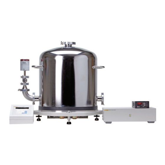
Fluke PG9000 Series Operation And Maintenance Manual (202 pages)
Piston Gauges
Brand:
Fluke
| Category:
Measuring Instruments
| Size: 5.04 MB
Table of Contents
Table of Contents
3
Tables
7
About this Manual
9
1 Introduction
11
Product Overview
11
Specifications
12
General Specifications
12
AMH Automated Mass Handler (Optional)
13
Embedded Features
13
Ambient and Instrument Condition Measurements
14
Piston-Cylinder Modules
15
Mass Sets
16
Pressure Measurements
16
Front and Rear Panels
17
PG Terminal Front and Rear Panels
17
Figure 1. PG Terminal Front Panel
17
Figure 2. PG Terminal Rear Panel
17
Remote Electronics Module (REM) Rear Panel
18
Base Rear Panel
18
Figure 3. PG9000 Remote Electronics Module Rear Panel
18
Figure 4. PG9602 Base Rear Panel
18
2 Installation
19
Unpacking and Inspection
19
Removing from Packaging
19
Platform
19
Piston-Cylinder Assemblies
20
Vacuum Reference Hardware (Optional)
20
AMH-100, Automated Mass Handler (Optional)
20
AMH Mass Set (Optional)
20
Manual Mass Set
20
Inspecting Contents
21
Platform
21
Table 1. PG9602 Parts List
21
Piston-Cylinder Modules
22
Table 2. Piston-Cylinder Modules Parts List
22
Vacuum Reference Hardware (Optional)
23
Table 3. PG9000 Vacuum Reference Hardware
23
AMH-100, Automated Mass Handler (Optional)
24
Mass Sets
24
Table 4. AHM-100-VAC Parts List
24
Table 5. Manual Mass Set Parts List (Excluding 80 and 100 Kg)
24
Table 6. Manual Mass Set Parts List (80 and 100 Kg)
24
Site Requirements
25
Table 7. AMH-100 Mass Set Parts List
25
Table 8. Mass Set Compositions
25
Table 9. Drive Air Pressure Requirement by Mass Set
26
Setup
27
Preparing for Operation
27
Setting up the Platform
28
Figure 5. Setting up the PG9602 Electrical Connections
28
System Pressure Interconnections
29
Setting up a Manual Mass Set
29
Figure 6. PG9602 Interconnections
29
Figure 7. Mass Sizes
30
Setting up an AMH Mass Set
31
Figure 8. Fractional Masses
31
Figure 9. AMH Mass Set
31
Setting up an AMH Automated Mass Handler (Optional)
32
Setting up Vacuum Reference Hardware (Optional)
34
Installing a Piston-Cylinder Module
35
Figure 10. Vacuum Vent Kit Assembly
35
Power up and Verification
36
Power up
36
Figure 11. Piston-Cylinder Module Installation
36
Verify Correct Piston-Cylinder and Mass Set Information
37
Set Local Gravity Value
37
Check/Set Security Level
37
Verify Input Sources
37
Verify Proper Operation of Ambient Conditions Measurements
38
Apply Pressure to the Piston-Cylinder Module
38
Check Proper Behavior of Motorized Piston Rotation
39
Verify Proper Operation of Piston Behavior Measurements
39
Verify Vacuum Reference
39
AMH Initialization / Startup
40
Check Automated Pressure Generation
41
Setup Verification Step to Take before Making Pressure Measurements
42
Short Term Storage
42
3 G E N E R a L O P E R a T I O
43
Fundamental Operating Principles
43
Figure 12. Piston Gauge Operating Principle
43
Keypad Layout and Protocol
44
Figure 13. PG9000 Keypad Layout
44
Sounds
45
Pressure Ready/Not Ready Indication
45
Piston Position Ready/Not Ready
46
Piston Rotation Rate Ready/Not Ready
46
Vacuum Reference Ready/Not Ready
47
Piston Position
47
Manual Mass Loading Protocol
48
Figure 14. Piston Stroke and Zones
48
AMH Mass Loading
50
Operating Principals
50
AMH Operation
52
Figure 15. AMH Cut Away View
52
Installing an AMH on the PG9000 Platform
53
Figure 16. AMH Installation on PG9000 Platform
53
Removing a Mass Handler from the PG9000 Platform
55
AMH Mass-To-Pressure or Pressure-To-Mass Operation
55
Direct Control of AMH Functions
55
Making and Breaking Reference Vacuum with AMH
56
Accessing the Piston-Cylinder Module with AMH
56
AMH Indicator LED
56
AMH Error Messages
57
Table 10. AMH Errors
57
Figure 17. AMH Indicator Location
57
Main Run Screen
59
General Function/Menu Flow Chart
60
Direct Function Keys
60
Direct Function Keys Summary
60
Figure 18. Run Screen Flow Chart
60
Table 11. Summary of PG9000 Direct Function Key Operations
61
[P-C]
62
Unit]
63
Customizing Pressure Units Available under the UNIT Function
64
Table 12. Pressure Units of Measure Available
64
Mode]
65
Differential Measurement Mode
66
Figure 19. Differential Mode Controller Schematic
68
Table 13. Valve Settings for Setting Differential Mode Static Pressure
69
Table 14. Valve Settings to Apply PG9000 Pressure to the RPM for Differential Mode Offsetting
70
Table 15. Valve Settings for Operating in Differential Mode
72
System]
73
First System Run Screen
74
Second System Run Screen
74
Third System Run Screen
75
Ambient]
76
Head]
77
Figure 20. PG9000 Platform Reference Level Location
78
Rotate]
79
2Pre-Decel
80
Gen]
81
2Target
83
3Raise
83
4Ul
83
5Tol
83
6Refloat
84
Res]
84
Ent / Set P]
86
ENT / SET P] in Pressure-To-Mass Mode
87
ENT / SET P] in Mass-To-Pressure Mode
88
Commands for Zero Pressure, Ending a Test
89
Por M]
89
And [ ] + [←]
90
SETUP] Menu
91
1Select
92
Table 16. SETUP File Choices, Factory Preferred Choice and Normal Value
92
2View
93
3Edit
94
SPECIAL] Menu
96
1Pc/Ms
97
Create a Piston-Cylinder Module
98
Edit a Piston-Cylinder Module
100
View a Piston-Cylinder Module
100
Delete a Piston-Cylinder Module
101
Select the Active Piston-Cylinder Module
101
Add a Mass Set
101
Edit a Mass Set
106
View a Mass Set
106
Delete a Mass Set
106
Select Mass Set
106
Add a Mass Loading Bell
107
Edit a Mass Loading Bell
108
View a Mass Loading Bell
108
Delete a Mass Loading Bell
109
Select a Mass Loading Bell
109
2Presu
109
3Head
109
3Head>, <1Fluid
110
3Head>, <2Unit
111
3Head>, <3Atm
111
3Head>, <4Piston
111
4Prefs
112
4Prefs>, <1Scrsvr
112
4Prefs>, <2Sound
112
4Prefs>, <3Time
113
4Prefs>, <4ID
113
4Prefs>, <5Level
114
Table 17. Security Levels - Functions NOT Executed Per Function/Level
115
5Remote
116
COM1, COM2, COM3 and COM4 (RS232)
117
Ieee-488
117
RS232 Self Test
117
Table 18. COM1, COM2, COM3 and COM4 Available Settings
117
External Barometer (RPM) Communications (COM2)
118
External Vacuum Gauge Communications (COM2)
120
6Gl
122
7Cal
123
8Amh
123
2Control>, <1Up/Down
124
2Control>, <2Discreet
124
2Control>, <3Loadall
124
2Control>, <4Unloadall
125
9Reset
125
9Reset>, <1Sets
125
9Reset>, <2Units
126
9Reset>, <3Com
126
9Reset>, <4Cal
127
9Reset>, <5Setups
127
9Reset>, <6All
127
4 Remote Operation
129
Overview
129
Interfacing
129
RS232 Interface
129
Com1
129
COM2, COM3 and COM4
130
Ieee-488 (Gpib)
130
Table 19. COM1 DB-9F Pin Designation
130
Table 20. COM2, COM3 and COM4 DB-9M Pin Designation
130
Commands
131
Command Syntax
131
Command Summary
131
Table 21. Command Summary
131
Error Messages
133
Table 22. Error Messages
133
AMH Errors
134
Command Descriptions
134
IEEE Std. 488.2 Common and Status Commands
134
Commands
136
Status System
161
Status Reporting System
161
Status Byte Register
161
Table 23. Status Byte Register
161
Figure 21. Status Byte Register
161
Standard Event Register
163
Table 24. Standard Event Register
163
1000 M a I N T E N a N C E , Ad J U S T M E N T S an D C a L I B R a T I O
165
Introduction
165
Platform
166
Calibration / Adjustment of On-Board Measurement Functions
166
Principles
166
Barometric Pressure Sensor
166
Ambient Temperature Sensor
167
Relative Humidity Sensor
168
Piston-Cylinder Module Temperature Sensors
168
Figure 22. PG9602 Bottom Panel Detail
169
Reference Vacuum Sensor (Optional)
170
Piston Position Detection Adjustment
171
Drive Belt Replacement
172
Piston-Cylinder Modules: Disassembly, Cleaning, and Maintenance
172
Disassembly and Reassembly: 10 and 20 Kpa/Kg
173
Figure 23. 10 Kpa/Kg Piston-Cylinder Module (Expanded View)
177
Figure 24. Gas Piston-Cylinder Module Sleeve Nut Tool
177
Piston Insertion Tool (10 Kpa/Kg Only)
178
Figure 25. 10 Kpa/Kg Piston Insertion Tool
178
Disassembly and Reassembly: 50, 100 and 200 Kpa/Kg
179
Cleaning Piston-Cylinders
182
Figure 26. 50, 100 and 200 Kpa/Kg Gas Piston-Cylinder Modules (Exploded View)
182
Water / Detergent Cleaning Method
183
Quick Method
183
Lubricating Piston-Cylinder Modules
184
Recalibration
185
Updating Piston-Cylinder Module Files
185
Updating Mass Set Files
185
Figure 27. Gas Operated, Gas Lubricated Piston-Cylinder Module Lubrication Chart
185
Mass Sets
186
Cleaning
186
Recalibration
186
Updating Embedded Software for
186
Disassembly and Reassembly of
186
Platform
186
Terminal
187
AMH Removal
187
6 T R O U B L E S H O O T I N
189
Overview
189
Table 25. PG9000 Troubleshooting Checklist
189
7 A P P E N D I
193
7. Appendix Conversion of Numerical Values
193
Pressure
193
Table 26. Pressure Unit of Measure Conversions
193
Defined Pressure Calculations
194
Table 27. PG9000 Defined Pressure Calculation Variables
194
Calculations
195
Fluid Head Components
196
Fluid Heads
196
Overall Fluid Head Correction
197
Glossary
198
Limited Warranty and Limitation of Liability
200
Table 28. Fluke Calibration Authorized Service Providers
201
Advertisement
Advertisement
Related Products
Fluke PG9602
FLUKE PG7607
Fluke PM6681
Fluke PM6681R/676/AF
Fluke PLS 3X360R
Fluke PRO3000 F50
Fluke PRO3000 F60
Fluke PLS 3X360G
Fluke PQ400
Fluke PQ Window
Fluke Categories
Measuring Instruments
Test Equipment
Multimeter
Thermometer
Laboratory Equipment
More Fluke Manuals
Login
Sign In
OR
Sign in with Facebook
Sign in with Google
Upload manual
Upload from disk
Upload from URL