Sign In
Upload
Manuals
Brands
Daikin Manuals
Air Conditioner
RXG25K2V1B
Daikin RXG25K2V1B Manuals
Manuals and User Guides for Daikin RXG25K2V1B. We have
5
Daikin RXG25K2V1B manuals available for free PDF download: Service Manual, Installation Manual
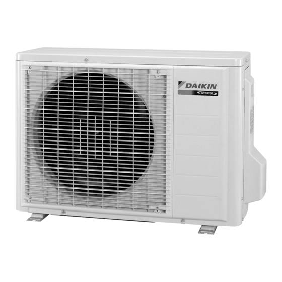
Daikin RXG25K2V1B Service Manual (242 pages)
Inverter Pair 
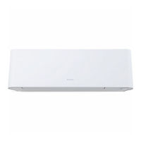
Wall Mounted Type J-Series
Brand:
Daikin
| Category:
Air Conditioner
| Size: 21.21 MB
Table of Contents
Table of Contents
3
Introduction
7
Safety Cautions
7
Used Icons
11
Part 1 List of Functions
12
Functions
13
Part 2 Specifications
15
Specifications
16
Part 3 Printed Circuit Board Connector Wiring Diagram
21
Indoor Unit
22
Outdoor Unit
25
Rxg25/35J2V1B, Rxg25/35K2V1B
25
Rxg50K2V1B
27
Part 4 Function and Control
29
Main Functions
30
Temperature Control
30
Frequency Principle
30
Operation Starting Control
32
Airflow Direction Control
33
Fan Speed Control for Indoor Unit
34
Program Dry Operation
35
Automatic Operation
36
Thermostat Control
37
NIGHT SET Mode
38
ECONO Operation
39
INTELLIGENT EYE Operation
40
Inverter POWERFUL Operation
41
Other Functions
43
Function of Thermistor
44
Control Specification
45
Mode Hierarchy
45
Frequency Control
46
Controls at Mode Changing / Start-Up
48
Compressor Protection Function
49
Discharge Pipe Temperature Control
50
Input Current Control
51
Freeze-Up Protection Control
52
Heating Peak-Cut Control
52
Outdoor Fan Control
53
Liquid Compression Protection Function
53
Defrost Control
54
Outdoor Electronic Expansion Valve Control
55
Pressure Equalizing Control
56
Malfunctions
58
Part 5 Operation Manual
59
System Configuration
60
Operation Manual
61
Name of Parts
61
Remote Controller
63
AUTO · DRY · COOL · HEAT · FAN Operation
65
Operating Conditions
66
Adjusting the Airflow Direction and Rate
67
COMFORT AIRFLOW Operation
69
INTELLIGENT EYE Operation
70
POWERFUL Operation
72
OUTDOOR UNIT QUIET Operation
73
ECONO Operation
74
During Operation
74
OFF TIMER Operation
75
ON TIMER Operation
76
WEEKLY TIMER Operation
77
Part 6 Service Diagnosis
83
Troubleshooting with LED
85
Indoor Unit
85
Outdoor Unit
85
Problem Symptoms and Measures
86
Service Check Function
87
Troubleshooting
90
Error Codes and Description
90
Indoor Unit PCB Abnormality
91
Freeze-Up Protection Control or Heating Peak-Cut Control
93
Fan Motor (DC Motor) or Related Abnormality
95
Thermistor or Related Abnormality (Indoor Unit)
97
Front Panel Open / Close Fault
98
Signal Transmission Error (between Indoor Unit and Outdoor Unit)
99
Unspecified Voltage (between Indoor Unit and Outdoor Unit)
101
Outdoor Unit PCB Abnormality
102
OL Activation (Compressor Overload)
104
Compressor Lock
105
DC Fan Lock
106
Input Overcurrent Detection
107
Four Way Valve Abnormality
108
Discharge Pipe Temperature Control
110
High Pressure Control in Cooling
111
Compressor System Sensor Abnormality
112
Position Sensor Abnormality
114
DC Voltage / Current Sensor Abnormality (25/35 Class)
117
CT or Related Abnormality (50 Class)
118
Thermistor or Related Abnormality (Outdoor Unit)
120
Electrical Box Temperature Rise
122
Radiation Fin Temperature Rise
124
Output Overcurrent Detection
126
Refrigerant Shortage
128
Low-Voltage Detection or Over-Voltage Detection
131
Signal Transmission Error on Outdoor Unit PCB (50 Class Only)
133
Check
134
Thermistor Resistance Check
134
Fan Motor Connector Check
135
Power Supply Waveforms Check
135
Electronic Expansion Valve Coil Check
136
Four Way Valve Performance Check
137
Inverter Unit Refrigerant System Check
137
Inverter Checker" Check
138
Rotation Pulse Check on the Outdoor Unit PCB
140
Installation Condition Check
141
Discharge Pressure Check
141
Outdoor Fan System Check
142
Main Circuit Short Check
142
Capacitor Voltage Check
143
Power Module Check
143
Part 7 Removal Procedure
144
Indoor Unit
145
Removal of Air Filters / Front Panel
145
Removal of Horizontal Blades
149
Removal of Front Grille
151
Removal of Front Panel Mechanism ASSY
154
Removal of Display Lens ASSY
156
Removal of Reduction Motor / Limit Switch
157
Removal of Fan Guards / Electrical Box
159
Removal of Pcbs
162
Removal of Swing Motors
168
Removal of Indoor Heat Exchanger
169
Removal of Fan Rotor / Fan Motor
172
Removal of Vertical Blade Assys
175
Outdoor Unit - 25/35 Class
176
Removal of Outer Panels / Fan Motor
176
Removal of Electrical Box
185
Removal of Pcbs
188
Removal of Reactor / Partition Plate
196
Removal of Sound Blankets
198
Removal of Four Way Valve
200
Removal of Compressor
203
Outdoor Unit - 50 Class
205
Removal of Outer Panels
205
Removal of Outdoor Fan / Fan Motor
209
Removal of Electrical Box
213
Removal of Pcbs
218
Removal of Sound Blankets / Thermistors
221
Removal of Four Way Valve
223
Removal of Electronic Expansion Valve
224
Removal of Compressor
225
Part 8 Trial Operation and Field Settings
228
Pump down Operation
229
Forced Cooling Operation
230
Trial Operation
232
Field Settings
233
When 2 Units Are Installed in 1 Room
233
Standby Electricity Saving
234
Jumper and Switch Settings
234
Application of Silicon Grease to a Power Transistor and a Diode Bridge
235
Part 9 Appendix
236
Piping Diagrams
237
Indoor Unit
237
Outdoor Unit
237
Wiring Diagrams
239
Indoor Unit
239
Outdoor Unit
239
Advertisement
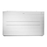
Daikin RXG25K2V1B Service Manual (243 pages)
Pair, Floor Standing Type K-Series, Heat Pump, Indoor/Outdoor Units
Brand:
Daikin
| Category:
Inverter
| Size: 11.36 MB
Table of Contents
Table of Contents
3
Introduction
7
Safety Cautions
7
Used Icons
11
Part 1 List of Functions
12
Functions
13
Part 2 Specifications
14
Specifications
15
Part 3 Printed Circuit Board Connector Wiring Diagram
17
Indoor Unit
18
Outdoor Unit
21
Rxg25/35K2V1B
21
Rxg50K2V1B
23
Part 4 Function and Control
25
Main Functions
26
Temperature Control
26
Frequency Principle
26
Airflow Direction Control
28
Fan Speed Control for Indoor Unit
29
RADIANT Operation
30
Indoor Unit Fan Control
31
Program Dry Operation
32
Automatic Operation
33
Thermostat Control
34
NIGHT SET Mode
35
ECONO Operation
36
Inverter POWERFUL Operation
37
Other Functions
38
Function of Thermistor
40
Control Specification
41
Mode Hierarchy
41
Frequency Control
42
Controls at Mode Changing / Start-Up
44
Discharge Pipe Temperature Control
46
Input Current Control
47
Freeze-Up Protection Control
48
Heating Peak-Cut Control
48
Outdoor Fan Control
49
Liquid Compression Protection Function
49
Defrost Control
50
Outdoor Electronic Expansion Valve Control
51
Malfunctions
54
Part 5 Operation Manual
55
System Configuration
56
Operation Manual
57
Names of Parts
57
Preparation before Operation
61
AUTO · DRY · COOL · HEAT · FAN Operation
63
RADIANT Operation
64
Temperature Setting
65
Adjusting the Airflow Direction and Rate
66
POWERFUL Operation
68
OUTDOOR UNIT QUIET Operation
69
ECONO Operation
70
OFF TIMER Operation
71
ON TIMER Operation
72
WEEKLY TIMER Operation
73
Quick Reference
79
Part 6 Service Diagnosis
80
Troubleshooting with LED
82
Indoor Unit
82
Outdoor Unit
82
Problem Symptoms and Measures
83
Service Check Function
84
Troubleshooting
87
Error Codes and Description
87
Indoor Unit PCB Abnormality
88
Freeze-Up Protection Control or Heating Peak-Cut Control
90
Fan Motor (DC Motor) or Related Abnormality
92
Radiant Panel Temperature Rise, Indoor Electronic Expansion Valve (Motor Operated Valve) Abnormality, Freeze-Up Protection Control
94
Thermistor or Related Abnormality (Indoor Unit)
96
Signal Transmission Error (between Indoor Unit and Outdoor Unit)
97
Unspecified Voltage (between Indoor Unit and Outdoor Unit)
99
Outdoor Unit PCB Abnormality
100
OL Activation (Compressor Overload)
102
Compressor Lock
103
DC Fan Lock
104
Input Overcurrent Detection
105
Four Way Valve Abnormality
106
Discharge Pipe Temperature Control
108
High Pressure Control in Cooling
109
Compressor System Sensor Abnormality
110
Position Sensor Abnormality
112
DC Voltage / Current Sensor Abnormality (25/35 Class)
115
CT or Related Abnormality (50 Class)
116
Thermistor or Related Abnormality (Outdoor Unit)
118
Electrical Box Temperature Rise
120
Radiation Fin Temperature Rise
122
Output Overcurrent Detection
124
Refrigerant Shortage
126
Low-Voltage Detection or Over-Voltage Detection
129
Signal Transmission Error on Outdoor Unit PCB (50 Class Only)
131
Check
132
Thermistor Resistance Check
132
Fan Motor Connector Check
133
Power Supply Waveforms Check
133
Electronic Expansion Valve Coil Check
134
Four Way Valve Performance Check
135
Inverter Unit Refrigerant System Check
135
Inverter Checker" Check
136
Rotation Pulse Check on the Outdoor Unit PCB
138
Installation Condition Check
139
Discharge Pressure Check
139
Outdoor Fan System Check
140
Main Circuit Short Check
140
Capacitor Voltage Check
141
Power Module Check
141
Part 7 Removal Procedure
142
Indoor Unit
143
Removal of Front Panel
143
Removal of Air Filters
144
Removal of Front Grille ASSY
145
Removal of Electrical Box / Pcbs
146
Removal of Horizontal Blade
159
Removal of Swing Motor
160
Removal of Radiant Panel
161
Removal of Air Outlet ASSY
166
Removal of Drain Pan / Indoor Heat Exchanger ASSY
168
Removal of Fan Rotor / Fan Motor
173
Outdoor Unit - RXG25/35K2V1B
178
Removal of Outer Panels / Fan Motor
178
Removal of Electrical Box
187
Removal of Pcbs
190
Removal of Reactor / Partition Plate
198
Removal of Sound Blankets
200
Removal of Four Way Valve
202
Removal of Compressor
205
Outdoor Unit - RXG50K2V1B
207
Removal of Outer Panels
207
Removal of Outdoor Fan / Fan Motor
211
Removal of Electrical Box
215
Removal of Pcbs
220
Removal of Sound Blankets / Thermistors
223
Removal of Four Way Valve
225
Removal of Outdoor Electronic Expansion Valve
226
Removal of Compressor
227
Part 8 Trial Operation and Field Settings
230
Pump down Operation
231
Forced Cooling Operation
232
Trial Operation
234
Field Settings
235
When 2 Units Are Installed in 1 Room
235
Standby Electricity Saving
236
Jumper and Switch Settings
236
Application of Silicon Grease to a Power Transistor and a Diode Bridge
237
Part 9 Appendix
238
Piping Diagrams
239
Indoor Unit
239
Outdoor Unit
240
Wiring Diagrams
241
Indoor Unit
241
Outdoor Unit
242
Daikin RXG25K2V1B Service Manual (147 pages)
Inverter Pair Floor Standing Type
Brand:
Daikin
| Category:
Heat Pump
| Size: 6.96 MB
Table of Contents
Table of Contents
3
Introduction
6
Safety Cautions
6
Used Icons
10
Part 1 List of Functions
11
Functions
12
Part 2 Specifications
14
Specifications
15
Part 3 Printed Circuit Board Connector Wiring Diagram
19
Indoor Unit
20
Outdoor Unit
22
25/35 Class
22
Rxg50K2V1B
24
Rxg50K3V1B
25
Part 4 Function and Control
27
Main Functions
28
Temperature Control
28
Frequency Principle
28
Airflow Direction Control
30
Fan Speed Control for Indoor Unit
31
RADIANT Operation
32
Program Dry Operation
34
Automatic Operation
35
Thermostat Control
36
NIGHT SET Mode
37
ECONO Operation
38
Inverter POWERFUL Operation
39
Clock Setting
40
WEEKLY TIMER Operation
41
Other Functions
47
Function of Thermistor
49
Control Specification
50
Mode Hierarchy
50
Frequency Control
51
Controls at Mode Changing / Start-Up
53
Discharge Pipe Temperature Control
54
Input Current Control
55
Freeze-Up Protection Control
56
Heating Peak-Cut Control
56
Outdoor Fan Control
57
Liquid Compression Protection Function
57
Defrost Control
58
Outdoor Electronic Expansion Valve Control
59
Pressure Equalizing Control
60
Malfunctions
62
Part 5 Remote Controller
63
Fvxg25/35/50K2V1B
64
Mode Button
65
Part 6 Service Diagnosis
66
Troubleshooting with LED
68
Indoor Unit
68
Outdoor Unit
68
Problem Symptoms and Measures
69
Service Check Function
70
Troubleshooting
73
Error Codes and Description
73
Indoor Unit PCB Abnormality
74
Freeze-Up Protection Control or Heating Peak-Cut Control
75
Fan Motor (DC Motor) or Related Abnormality
76
Radiant Panel Temperature Rise, Indoor Electronic Expansion Valve (Motor Operated Valve) Abnormality, Freeze-Up Protection Control
78
Thermistor or Related Abnormality (Indoor Unit)
80
Refrigerant Shortage
81
Low-Voltage Detection or Over-Voltage Detection
84
Signal Transmission Error (between Indoor Unit and Outdoor Unit)
86
Signal Transmission Error on Outdoor Unit PCB (RXG50K2V1B Only)
88
Unspecified Voltage (between Indoor Unit and Outdoor Unit)
89
Outdoor Unit PCB Abnormality
90
OL Activation (Compressor Overload)
92
Compressor Lock
94
DC Fan Lock
95
Input Overcurrent Detection
96
Four Way Valve Abnormality
97
Discharge Pipe Temperature Control
99
High Pressure Control in Cooling
100
Compressor System Sensor Abnormality
101
Position Sensor Abnormality
103
DC Voltage / Current Sensor Abnormality (25/35 Class Only)
106
CT or Related Abnormality (RXG50K2V1B Only)
107
Thermistor or Related Abnormality (Outdoor Unit)
109
Electrical Box Temperature Rise
111
Radiation Fin Temperature Rise
112
Output Overcurrent Detection
114
Check
116
Thermistor Resistance Check
116
Fan Motor Connector Output Check
117
Power Supply Waveforms Check
117
Electronic Expansion Valve Check
118
Four Way Valve Performance Check
119
Inverter Units Refrigerant System Check
119
Inverter Analyzer Check
120
Rotation Pulse Check on the Outdoor Unit PCB
122
Installation Condition Check
123
Discharge Pressure Check
123
Outdoor Fan System Check
124
Main Circuit Short Check
124
Capacitor Voltage Check
125
Power Module Check
126
Part 7 Trial Operation and Field Settings
128
Pump down Operation
129
Forced Cooling Operation
130
Trial Operation
132
Field Settings
133
When 2 Units Are Installed in 1 Room
133
Standby Electricity Saving
134
Facility Setting Jumper (Cooling at Low Outdoor Temperature)
135
Jumper and Switch Settings
136
Silicon Grease on Power Transistor / Diode Bridge
137
Part 8 Appendix
138
Piping Diagrams
139
Indoor Unit
139
Outdoor Unit
140
Wiring Diagrams
142
Indoor Unit
142
Outdoor Unit
143
Removal Procedure (Booklet No.)
145
Revision History
146
Advertisement
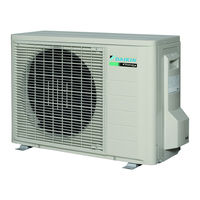
Daikin RXG25K2V1B Service Manual (33 pages)
2.0/2.5/3.5 kW Class 9000/12000 Btu/h Class
Brand:
Daikin
| Category:
Air Handlers
| Size: 2.3 MB
Table of Contents
Table of Contents
3
Removal of Outer Panels / Fan Motor
4
Removal of Electrical Box
13
Removal of Pcbs
16
Removal of Reactor / Partition Plate
23
Removal of Sound Blankets
25
Removal of Four Way Valve
27
Removal of Compressor
30
Daikin RXG25K2V1B Installation Manual (17 pages)
Brand:
Daikin
| Category:
Air Conditioner
| Size: 2.03 MB
Table of Contents
Safety Precautions
5
Precautions for Selecting the Location
6
Outdoor Unit Installation Drawings
7
Precautions on Installation
8
Outdoor Unit Installation
8
Standby Electricity Saving
12
Pump down Operation
13
Trial Operation and Testing
15
Advertisement
Related Products
Daikin RXG25CVMA
Daikin RXG25CVMB
Daikin RXG25J2V1B
Daikin RXG25E3V1B
Daikin RXG25L2V1B
Daikin RXG25JV2C
Daikin RXG25E2V1B
Daikin RXG20L2V1B
Daikin RX-GV
Daikin RXG35E3V1B
Daikin Categories
Air Conditioner
Heat Pump
Remote Control
Chiller
Fan
More Daikin Manuals
Login
Sign In
OR
Sign in with Facebook
Sign in with Google
Upload manual
Upload from disk
Upload from URL