Sign In
Upload
Manuals
Brands
Club Car Manuals
Golf Cars
Carryall 500 2016
Club Car Carryall 500 2016 Manuals
Manuals and User Guides for Club Car Carryall 500 2016. We have
1
Club Car Carryall 500 2016 manual available for free PDF download: Maintenance And Service Manual
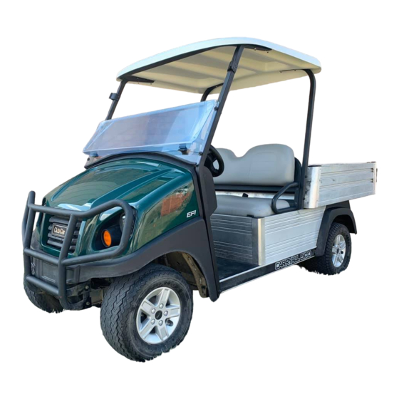
Club Car Carryall 500 2016 Maintenance And Service Manual (472 pages)
Gasoline Vehicle with Subaru EX40 Engine Electric Vehicle with QuiQ Charger
Brand:
Club Car
| Category:
Golf Cars
| Size: 66.98 MB
Table of Contents
Table of Contents
5
SECTION 1 - Safety
17
Safety Details
17
Personal Safety
17
Machine Safety
17
Information
17
General Warnings
17
Disabling the Vehicle
20
Disconnecting the Batteries - Electric Vehicles
20
Connecting the Batteries - Electric Vehicles
20
Side-Post Battery: Disconnecting the Battery-Gasoline Vehicles
21
Side-Post Battery: Connecting the Battery-Gasoline Vehicles
21
Top-Post Battery: Disconnecting the Battery-Gasoline Vehicles
21
Top-Post Battery: Connecting the Battery-Gasoline Vehicles
21
Recycling Lead-Acid Batteries
22
International Safety Symbols on Batteries
22
SECTION 2 - Vehicle Specifications
24
Vehicle Specifications
24
Quiq Battery Charger Specifications
25
Vehicle Specifications - Gasoline Vehicles
26
SECTION 3 - General Information
29
Model Identification
29
Storage - Electric Vehicles
30
Preparing the Electric Vehicle for Extended Storage
30
Returning the Stored Electric Vehicle to Service
31
Storage - Gasoline Vehicles
32
Preparing the Gasoline Vehicle for Extended Storage
32
Returning the Stored Gasoline Vehicle to Service
33
SECTION 4 - Body and Trim
35
Cleaning the Vehicle
35
Seat Cleaning
35
Front Body Repair
36
Light Scratches
36
Abrasions and Haze
36
Large Scratches and Abrasions
36
Touch-Up Paint Color Chart
36
Front Body
37
Heavy Duty Bumper Removal
37
Heavy Duty Bumper Installation
39
Cowl Removal
39
Cowl Installation
39
Grille Removal
40
Grille Installation
41
Front Bumper and Side Fender Removal
43
Front Bumper and Side Fender Installation
43
Instrument Panel Removal
44
Instrument Panel Installation
44
Dash Removal
45
Dash Installation
45
Tilt Bed
47
Tilt Bed Removal
47
Tilt Bed Installation
47
Bed Latch Assembly Removal
49
Bed Latch Assembly Installation
49
Rear Fenders and Tailskirt
51
Rear Fender and Tailskirt Removal
51
Rear Fender and Tailskirt Installation
52
Electric Bed Lift
53
Electric Bed Lift Removal
53
Electric Bed Lift Installation
53
Floor Mat
56
Floor Mat Removal
56
Floor Mat Installation
56
Trailer Hitch
56
Trailer Hitch Removal
56
Trailer Hitch Installation
56
SECTION 5 - Accelerator and Brake Pedal Group
57
Brake Pedal and Park Brake (Gas and Electric Vehicles)
57
Brake Pedal Removal (Gas and Electric Vehicles)
57
Brake Pedal Installation (Gas and Electric Vehicles)
57
Park Brake Removal (Gas and Electric Vehicles)
60
Park Brake Installation (Gas and Electric Vehicles)
60
Accelerator Pedal - Gasoline Vehicles
61
Accelerator Pedal Removal - Gasoline Vehicles
61
Accelerator Pedal Installation - Gasoline Vehicles
62
Accelerator Pedal - Electric Vehicles
63
Accelerator Pedal Removal - Electric Vehicles
63
Accelerator Pedal Installation - Electric Vehicles
66
Pedal Group Adjustment - Gasoline Vehicles
66
Pedal Group Adjustment - Electric Vehicles
72
SECTION 6 - Wheel Brake Assemblies
77
General Information
77
Brake Shoe Removal
77
Brake Assembly Cleaning
79
Brake Shoe Installation
81
Brake Adjustment
82
Brake Cluster Adjustment
83
Brake Cable Equalization
85
Final Brake Cluster Adjustment
86
Test Drive Vehicle
86
Brake Cluster Removal and Installation
87
Front Brake Cluster Removal
87
Front Brake Cluster Installation
87
Rear Brake Cluster Removal
89
Rear Brake Cluster Installation
89
Front Brake Cables
90
Front Brake Cable Removal
91
Front Brake Cable Installation
91
Rear Brake Cables
92
Rear Brake Cable Removal
93
Rear Brake Cable Installation
93
SECTION 7 - Steering and Front Suspension
95
General Information
95
Steering Wheel
95
Steering Wheel Removal
95
Steering Wheel Installation
96
Steering Column
97
Steering Column Removal
98
Steering Column Disassembly
98
Steering Column Assembly
98
Steering Column Installation
99
Steering Adjustment
100
Rack and Pinion
101
Rack and Pinion Inspection
101
Rack and Pinion Removal - Maintenance-Free Ball Joints
101
Rack and Pinion Disassembly
102
Rack and Pinion Assembly
104
Rack and Pinion Installation - Maintenance-Free Ball Joints
107
Tie Rod and Drag Link
108
Tie Rod and Drag Link Removal - Maintenance-Free Ball Joints
108
Tie Rod and Drag Link Installation - Maintenance-Free Ball Joints
108
Front Suspension
109
Lubrication
109
Wheel Alignment
109
Front Suspension Components
111
Leaf Spring Removal
111
Leaf Spring Installation
111
Kingpin and Steering Spindle Removal - Maintenance-Free Ball Joints
111
Kingpin and Steering Spindle Installation - Maintenance-Free Ball Joints
114
Delta A-Plate Removal
114
Delta A-Plate Installation
114
Shock Absorber Removal
114
Shock Absorber Installation
114
Front Wheel Bearings and Hubs
115
Front Wheel Free Play Inspection
115
Front Hub and Wheel Bearings Removal
115
Front Hub and Wheel Bearings Installation
116
SECTION 8 - Wheels and Tires
117
General Information
117
Wheels
117
Wheel Removal
117
Wheel Installation
117
Tires
118
Tire Removal
118
Tire Repair
118
Tire Installation
119
SECTION 9 - Rear Suspension
121
General Information
121
Shock Absorbers
121
Shock Absorber Inspection and Removal
121
Shock Absorber Installation
121
Multi-Leaf Springs
122
Multi-Leaf Spring Removal
122
Multi-Leaf Spring Installation
123
SECTION 10 - Periodic Maintenance
125
General Information
125
Pre-Operation and Daily Safety Checklist
125
Performance Inspection
126
Maintenance
127
Periodic Service Schedules
128
Periodic Lubrication Schedules
131
SECTION 11 - Controller Diagnostic Tool (CDT)
133
General Information
134
Features
134
Plugging the CDT into the Vehicle
134
Introductory Display
135
Quick Reference Guide - IQ Plus with Quiq Charger
136
Battery Monitor
147
Charging Totals
147
Amp Hours Display
147
Lin
147
Diagnostics Menu
149
Present Errors Folder
149
Fault History Folder
149
System Faults
149
Fault Recovery
151
Fault Descriptions
152
02 Low Battery Voltage
152
03 Overvoltage
152
04 Thermal Cutback
152
06 Hpd
152
07 Main Welded
152
08 Relay Welded
152
09 Speed Sensor
152
10 Main Driver on
152
11 Main Coil Open
152
12 Main Dropout
153
13 Motor Stall
153
14 Main Driver off
153
15 Relay Dnc
153
16 Keyswitch Sro
153
17 Current Sense
153
18 M- Shorted
153
20 Driver Overcurrent
153
21 Precharge Fault
153
22 Field Missing
153
25 Incorrect Password
154
26 Circuit Brkr Open
154
27 Max Password Tries
154
29 Relay Drvr off
154
30 Relay Coil Fault
154
Anti-Tamper Fault
154
Lockout Fault
154
Low SOC
154
Main CONT DNC
155
Main Coil Fault
155
Proc/Wiring
155
Open Armature
155
Incorrect Password (OEM Access Level Only)
155
Fault History
155
Clearing Fault History
155
Programming
156
Cloning
156
Favorites
156
HHP Settings
157
Plot & Log
158
Plot
158
Log
158
CDT Troubleshooting
159
Connection Tests
160
SECTION 12 - Electrical System Troubleshooting: IQ Plus Electric Vehicles
163
General Information
163
Accessories
163
Charge Indicator Light
163
Key Differences: IQ Plus with Quiq Charger Vs. IQ Plus Charger
163
Features
164
Wiring Diagrams
166
Troubleshooting
170
Troubleshooting the Vehicle with the CDT
170
Troubleshooting Guide 2
174
Test Procedures
176
Testing Basics
176
SECTION 13 - Electrical Components: IQ Plus Electric Vehicles
207
Key Switch
207
Testing the Key Switch
207
Key Switch Removal
207
Key Switch Installation
207
Forward/Reverse Rocker Switch
209
Forward/Reverse Rocker Switch Removal
209
Forward/Reverse Rocker Switch Installation
209
Tow/Run Switch
209
Tow/Run Switch Removal
210
Tow/Run Switch Installation
210
Circuit Breaker
210
Circuit Breaker Removal
210
Circuit Breaker Installation
210
Motor Controller Output Regulator (MCOR)
212
Testing the MCOR
212
MCOR Removal
212
MCOR Installation
212
Reverse Buzzer
213
Reverse Buzzer Removal
213
Reverse Buzzer Installation
213
Speed Controller Cover
213
Removing the Speed Controller Cover
213
Installing the Speed Controller Cover
213
Solenoid
214
Solenoid Removal
214
Solenoid Installation
214
Speed Controller
215
Speed Controller Removal
215
Speed Controller Installation
215
Charge Indicator Light
217
Testing the Charge Indicator Light
217
Charge Indicator Light Removal
217
Charge Indicator Light Installation
217
SECTION 14 - Batteries: IQ Plus Electric Vehicles
219
General Information
219
Battery Testing Basics - 6 Volt
220
Observation
220
Measuring Voltage of Battery Set
220
Battery Cell Numbering
220
Battery Testing - 6 Volt
221
Battery Regrouping
221
Battery Replacement
223
Battery Care
224
Water Quality
224
Deionizer
225
Battery Care - Vehicles Equipped with the Single-Point Watering System (SPWS)
226
Battery Care - Vehicles Without the Single-Point Watering System (SPWS)
227
Self-Discharge
228
Electrolyte Level
228
Vibration Damage
229
Single Point Watering System (SPWS)
229
Initial Maintenance of the SPWS
229
Watering Batteries with the SPWS
229
Battery Storage
231
Fleet Rotation
231
Deep-Discharge
232
Early Excessive Discharging
232
SECTION 15 - Quiq High Frequency Charger
233
General Information
233
Features
233
UL and CSA Listing
233
CE Compliance
233
IP (Ingress Protection) Rating
233
How to Identify Charge Algorithm Number
234
The Charge Circuit
235
Onboard Charger Operation
235
Charger Displays
237
AC Power Connection
239
Charging Batteries
239
Maintenance
240
Troubleshooting
241
Test Procedures
242
Charger Repairs
243
Onboard Charger Removal and Installation
243
Onboard Charger Removal
243
Onboard Charger Installation
244
SECTION 16 - Motor (Model DA5-4006): Electric Vehicles
245
General Information
245
External Motor Testing
245
Motor Removal
246
Motor Disassembly
248
Motor Component Testing and Inspection
251
Armature Inspection and Testing
251
Motor Frame and Field Windings Inspection
252
Motor Brush, Spring, and Terminal Insulator Inspection
252
Reconditioning the Motor
255
Motor Specifications
255
Motor Assembly
255
Motor Installation
257
SECTION 17 - Transaxle: Electric Vehicles
261
Lubrication
261
Axle Bearing and Shaft
261
Axle Shaft
261
Axle Bearing
264
Transaxle
265
Transaxle Removal
265
Transaxle Disassembly, Inspection, and Assembly
268
Transaxle Disassembly and Inspection
268
Transaxle Assembly
270
Transaxle Installation
272
SECTION 18 - Troubleshooting and Electrical System: Pedal-Start Gas Vehicle
273
General Information
273
Accessories
273
Low Oil Warning Light
273
Ground Locations
273
Features of the Electronic Fuel Injection (EFI) System
274
Troubleshooting Guide
274
ECU Error Codes (Displayed by the Low Oil Warning Light)
274
Advertisement
Advertisement
Related Products
Club Car Carryall 500
Club Car Carryall 500 2019
Club Car Carryall 500 2015
Club Car Carryall 550
Club Car Carryall 550 2017
Club Car CARRYALL 502 ELECTRIC
Club Car Carryall 550 2015
Club Car Carryall 550 2019
Club Car Carryall 1500 IntelliTach
Club Car Carryall 700
Club Car Categories
Golf Cars
Utility Vehicle
Offroad Vehicle
Electric Vehicles
Battery Charger
More Club Car Manuals
Login
Sign In
OR
Sign in with Facebook
Sign in with Google
Upload manual
Upload from disk
Upload from URL