Sign In
Upload
Manuals
Brands
Canon Manuals
Printer Accessories
Puncher Unit-L1
Canon Puncher Unit-L1 Manuals
Manuals and User Guides for Canon Puncher Unit-L1. We have
7
Canon Puncher Unit-L1 manuals available for free PDF download: Service Manual, Portable Manual, Installation Procedure, Circuit Diagram, General Timing Chart/General Circuit Diagram
Canon Puncher Unit-L1 Service Manual (92 pages)
Finisher, Sorter, DeliveryTray
Brand:
Canon
| Category:
Printer Accessories
| Size: 2.72 MB
Table of Contents
Table of Contents
7
Chapter 1 Specifications
11
Product Specifications/Names of Parts
13
Product Specifications
15
1Specifications
15
Specifications
15
Names of Parts
17
1External View
17
External View
17
2Cross Section
18
Cross Section
18
Chapter 2 Functions
19
Table of Contents
21
Basic Construction
23
1Functional Construction
23
Functional Construction
23
Feed Drive System
24
1Overview
24
Overview
24
2Constraction of the Control System
24
Constraction of the Control System
24
3Punch Operation
26
Punch Operation
26
4Horizontal Registration Operation
29
Horizontal Registration Operation
29
Detecting Jams
32
Power Supply
33
1Power Supply Route
33
Power Supply Route
33
2Protection Function
33
Protection Function
33
Chapter 3 Parts Replacement Procedure
35
Table of Contents
37
External Covers
39
Rear Cover
39
Removing the Rear Cover
39
Upper Cover
39
Removing the Upper Cover
39
Right Guide Unit
39
Removing the Right Guide Unit
39
Drive System
40
Punch Motor
40
Removing the Rear Cover
40
Removing the Upper Cover
40
Removing the Punch Motor
40
Horizontal Registration Motor
40
Removing the Rear Cover
41
Removing the Right Guide Unit
41
Removing the Horizontal Registration Motor
41
Punch Unit
41
Notification When Dismounting the Punch Unit
41
Removing the Right Guide Unit
42
Removing the Upper Cover
42
Removing the Punch Unit
42
Electrical System
45
Punch Unit Harness
45
Notification When Dismounting the Punch Unit Harness
45
Removing the Rear Cover
45
Removing the Right Guide Unit
45
Removing the Upper Cover
45
Removing the Punch Unit Harness
45
Installing the Punch Unit Harness
47
Led Pcb
47
Removing the Rear Cover
47
Removing the Right Guide Unit
48
Removing the Upper Cover
48
Removing the Punch Unit
48
Removing the LED PCB
50
Photosensor PCB
50
Removing the Rear Cover
50
Removing the Upper Cover
51
Scrap Full Detector PCB
51
Removing the Right Guide Unit
51
Removing the Scrap Full Detector PCB
51
Punch Controller PCB
52
Removing the Rear Cover
52
Removing the Punch Controller PCB
52
Chapter 4 Maintenance
53
Table of Contents
55
User Maintenance
57
Maintenance and Inspection
58
Periodically Replaced Parts
58
Durables
58
Periodical Servicing
58
Adjustment
59
Adjustment at Time of Parts Replacement
59
Adjusting the Punch Hole Position (Feed Direction)
59
Registering the Number of Punch Holes
59
Troubleshooting
61
Error Code
61
E503; Puncher Unit Communication Error
61
E505; Backup RAM Error
61
E590; Punch Motor Error
61
E591; Scrap Full Detector Sensor Error
62
E592; Trailing Edge/Horizontal Registration Sensor Error
62
E593; Horizontal Registration Motor Error
62
Outline of Electrical Components
63
Sensors
63
Microswitches
64
Motors
65
Pcbs
66
Variable Resistors (VR), Light-Emitting Diodes (LED), and Check Pins by PCB
68
Variable Resistors (VR), Light-Emitting Diodes (LED), and
68
Overview
68
Punch Controller PCB
68
Upgrading
69
Service Tools
77
Solvents and Oils
77
Chapter 5 Error Code
79
Table of Contents
81
Overview
83
User Error Code
84
Punch Scrap Full
84
Punch Scrap Overflow
84
Service Error Code
85
E503
85
E505
85
E590
85
E591
86
E592
87
E593
90
Advertisement
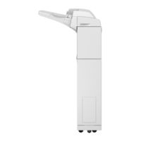
Canon Puncher Unit-L1 Service Manual (96 pages)
Paper Folding
Brand:
Canon
| Category:
Office Equipment
| Size: 5.18 MB
Table of Contents
Table of Contents
5
Safety Precautions
8
Points to Note before Servicing
9
Points to Note at Cleaning
9
Notes on Assembly/Disassembly
9
Handling of Packaging Materials
9
Product Overview
11
Features
12
Specifications
13
Z-Fold Position
13
Name of Parts
15
External View
15
Cross Section
16
Technical Explanation
18
Basic Configuration
19
Functional Configuration
19
Overview of Electrical Circuitry
19
Component Configuration
20
Drive Configuration
21
Controls
22
Basic Operation
23
Outline
23
Through-Feed Operation
23
Z-Fold Operation
24
Inlet Unit
29
Fold Unit
30
Fold-Enhancing Unit
32
Jam Detection
34
Outline
34
Jam Type
34
Power Supply
35
Power Supply Route
35
Protection Function
35
Upgrading
36
Periodical Service
37
List of Work for Scheduled Servicing
38
Parts Replacement and Cleaning
39
Removing this Machine from the Host Machine
40
Removing the Paper Folding Unit
40
List of Parts
46
External Covers
46
Main Units
47
Consumable Parts Requiring Periodic Replacement and Cleaning Points
48
List of Motors/Pcb
49
List of Sensors/Switch
50
Other Parts
51
External Cover
52
Removing the Rear Cover
52
Removing the Front Cover
53
Main Unit
54
Removing the Upper Cover Unit
54
Removing the Fold-Enhancing Unit
55
Removing the Motor Unit
60
Periodic Replacing Parts, Durable Parts, Cleaning Parts
61
Cleaning the Registration Roller (Upper)
61
Cleaning the Folding Roller
61
Motor
63
Removing the Registration Motor (M1)
63
Removing the Fold Motor (M2)
63
Removing the Pushing Plate Motor (M3)
64
Removing the Fold-Enhancing Motor (M4)
65
Sensor
67
Removing the Pre-Registration Sensor (PS1)
67
Removing the Pushing Plate HP Sensor (PS2)
68
Removing the Fold-Enhancing HP Sensor (PS3)
69
Removing the Fold-Enhancing Motor Clock Sensor (PS4)
70
Removing the Registration Disengagement HP Sensor (PS5)
71
Removing the Post-Fold Sensor (PS6)
71
Pcb
73
Removing the Paper Folding Unit Controller PCB
73
Other Parts
75
Removing the Registration Roller (Upper)
75
Removing the Folding Roller (Upper)
75
Removing the Folding Roller (Lower)
78
Removing the Pushing Plate
79
Removing the Buffer Pass Unit Connecting Plate
80
Adjustment
82
Overview
83
Service Mode
83
Adjustments When Replacing Parts
84
Basic Adjustment
85
Adjustment of the Z-Fold Position
85
Adjustment of the Tab Length of Z-Fold
86
Adjustment When Replacing the Parts
87
Handling When Replacing the Paper Folding Unit Controller PCB
87
Handling When Replacing the Upper Cover Unit
88
Adjustment When Replacing the Fold-Enhancing Unit
88
Handling When Replacing the Pushing Plate HP Sensor (PS2)
92
Handling When Replacing the Post-Fold Sensor (PS6)
92
Handling When Replacing the Fold-Enhancing Motor (M4)
92
Service Label
93
Back-Up of Service Mode
93
Appendices
94
Service Tools
95
Solvents and Oils
95
Special Tools
95
General Circuit Diagram
96
Canon Puncher Unit-L1 Portable Manual (54 pages)
Finisher, Sorter, DeliveryTray
Brand:
Canon
| Category:
Printer Accessories
| Size: 0.47 MB
Table of Contents
Table of Contents
7
Chapter 1 Maintenance And Inspection
9
Periodically Replaced Parts
13
Durables
14
Periodical Servicing
15
Chapter 2 Standards And Adjustments
17
Adjustment at Time of Parts Replacement
21
Chapter 3 Error Code
23
Table of Contents
25
User Error Code
27
1Punch Scrap Full
27
2Punch Scrap Overflow
27
Service Error Code
28
E503
28
E505
28
E590
28
E591
29
E592
30
E593
33
Outline of Electrical Components/Variable Resistors (Vr), Light-Emitting Diodes (Led), and
37
Outline of Electrical Components
39
Sensors
39
Motors
39
Microswitches
40
Motors
41
Pcbs
42
Punch Controller PCB
42
Variable Resistors (VR), Light-Emitting Diodes (LED), and
44
Overview
44
Punch Controller PCB
44
Chapter 4 Outline of Components
47
Basic Construction
47
Chapter 5 System Construction
47
Advertisement
Canon Puncher Unit-L1 Portable Manual (54 pages)
Finisherm sorter, DeliveryTray
Brand:
Canon
| Category:
Printer Accessories
| Size: 0.44 MB
Table of Contents
Table of Contents
7
Chapter 1 Maintenance And Inspection
9
Periodically Replaced Parts
13
Durables
14
Periodical Servicing
15
Chapter 2 Standards And Adjustments
17
Adjustment at Time of Parts Replacement
21
Chapter 3 Error Code
23
User Error Code
27
1Punch Scrap Full
27
2Punch Scrap Overflow
27
Service Error Code
28
E503
28
E505
28
E590
28
E591
29
E592
30
E593
33
Outline of Electrical Components
39
Sensors
39
Microswitches
40
Motors
41
Pcbs
42
Variable Resistors (VR), Light-Emitting Diodes (LED), and
44
Overview
44
Punch Controller PCB
44
Canon Puncher Unit-L1 Installation Procedure (40 pages)
Finisher, Sorter, DeliveryTray
Brand:
Canon
| Category:
Printer Accessories
| Size: 3.03 MB
Table of Contents
Table of Contents
7
Making Pre-Checks
10
1Checking the Contents
10
2Installing the Accessories
12
Unpacking and Checking the Components
16
1Unpacking
16
Installation Procedure
17
1Disconnecting the Finisher from Its Host Machine
17
2Connecting to the Finisher
20
3Preparing the Host Machine for Installation
23
4Connecting to the Host Machine
26
5Checking the Height/Tilt
27
Making Adjustments
30
1Adjusting the Height/Tilt
30
2Work after Making Checks/Adjustments
33
Attaching the Labels Etc
37
1Attaching the Label
37
Canon Puncher Unit-L1 Circuit Diagram (20 pages)
Finisher, Sorter, DeliveryTray
Brand:
Canon
| Category:
Printer Accessories
| Size: 0.26 MB
Table of Contents
Table of Contents
5
1 Punch Controller PCB
7
Punch Controller PCB(A501)
7
Punch Controller PCB(A502)
8
Punch Controller PCB(A503)
9
Punch Controller PCB(A504)
10
2 Scrap Full Detector PCB
11
3 Led Pcb
13
4 Photosensor PCB
15
Canon Puncher Unit-L1 General Timing Chart/General Circuit Diagram (14 pages)
Finisher, Sorter, DeliveryTray
Brand:
Canon
| Category:
Printer Accessories
| Size: 0.19 MB
Table of Contents
Table of Contents
5
1 Genelal Timing Chart
7
Punching : A4 Size Paper, 2-Sheet Document, Job Offset
7
2 General Circuit Diagram
9
Signal Names
9
General Circuit Diagram
10
Advertisement
Related Products
Canon Cassette Feeding Unit-AP1
Canon Duplex Unit-A1
Canon Puncher Unit-N1
Canon Puncher Unit-P1
Canon Cassette Heater Unit 27
Canon Paper Deck Unit-B2
Canon Paper Deck Unit-B1
Canon Decurler Unit-C1
Canon imageFORMULA Flatbed Scanner Unit 102
Canon Cassette Feeding Unit-AM1
Canon Categories
Printer
Digital Camera
All in One Printer
Camcorder
Scanner
More Canon Manuals
Login
Sign In
OR
Sign in with Facebook
Sign in with Google
Upload manual
Upload from disk
Upload from URL