Sign In
Upload
Manuals
Brands
Canon Manuals
Fax Machine
L100 Series
Canon L100 Series Manuals
Manuals and User Guides for Canon L100 Series. We have
3
Canon L100 Series manuals available for free PDF download: Service Manual
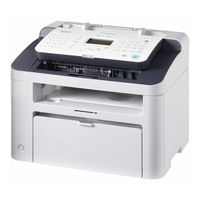
Canon L100 Series Service Manual (186 pages)
Brand:
Canon
| Category:
Printer
| Size: 30.12 MB
Table of Contents
Table of Contents
4
Safety Precautions
10
CDRH Provisions
11
Laser Safety
11
About Laser Beams
11
Handling Laser Scanner Unit
11
Toner Safety
12
About Toner
12
Handling Adhered Toner
12
Notes on Handling Lithium Battery
12
Notes on Assembly/Disassembly
12
1 Product Overview
13
Product Lineup
13
Host Machine
14
L150
14
L150 Chn / L150 Kor / L154
14
Product Features
14
Specifications
15
Product Specifications
15
ADF Specifications
15
FAX Specifications
16
Parts Name
16
External View
16
Front Side of the Machine (L100 / L170 / L174)
16
Rear Side of the Machine (L100 / L170 / L174)
17
Front Side of the Machine (L150)
18
Front Side of the Machine (L150 CHN / L150 KOR / L154)
19
Rear Side of the Machine (L150)
19
Rear Side of the Machine (L150 CHN / L150 KOR / L154)
20
Cross Sectional View
21
Operation Panel (L100 / L170 / L174)
21
Operation Panel (L150 / L150 CHN / L150 KOR / L154)
22
2 Technical Overview
24
Basic Configuration
24
Configuration Function
25
Basic Sequence
25
Basic Sequence of Operation
25
Print Sequence
26
Power-On Sequence
27
Controller System
28
Main Controller
28
Overview
28
Engine Controller
28
General Description
28
Power Supply
29
Protective Functions
29
Service Tasks
30
At Parts Replacement
30
Maintenance
30
Notes on Service Tasks
30
Original Exposure System
31
Overview
31
Major Components
31
Various Control
31
Detecting Jam
32
Jam Detection Outline
32
Service Tasks
32
At Parts Replacement
32
Maintenance
32
Notes on Service Tasks
32
Laser Exposure System
33
Overview
33
Controlling the Laser Activation Timing
34
Laser ON/OFF Control
34
Horizontal Sync Control
34
Laser Control
35
Auto Power Control (APC)
35
Laser Scanner Motor Control
35
Overview
35
Scanner Motor Fault Detection
36
Service Tasks
36
At Parts Replacement
36
Maintenance
36
Notes on Service Tasks
36
Image Formation System
37
Overview/Configuration
37
Overview
37
Print Process
37
Development Block
38
Static Latent Image Formation Block
38
Drum Cleaning Block
39
Fixing Block
39
Transfer Block
39
High-Voltage Control
40
Generating Developing Bias
40
Generating Primary Charging Bias
40
Generating Transfer Bias
40
Overview
40
Toner Cartridge
41
Operation When Toner Level Is Low/Nearly out
41
Specification of Toner Level Display
41
Toner Level Detection
41
Toner Cartridge Absence/Presence Detection
42
Service Tasks
42
At Parts Replacement
42
Maintenance
42
Notes on Service Tasks
42
Fixing System
43
Overview/Configuration
43
Main Parts of Fixing Assembly
43
Overview
43
Fixing Temperature Control
44
Protective Functions
44
Various Control Mechanisms
44
Failure Detection
45
Other Functions
46
Throughput down Control
46
At Parts Replacement
47
Maintenance
47
Notes on Service Tasks
47
Service Tasks
47
Pickup Feed System
48
Overview
48
Delay Jam
49
Delivery Delay Jam
49
Detecting Jams
49
Jam Detection Outline
49
Delivery Stationary Jam
51
Other Jams
51
Pickup Stationary Jam
51
Stationary Jam
51
At Parts Replacement
52
Maintenance
52
Notes on Service Tasks
52
Service Tasks
52
3 Periodical Services
53
Periodically Replaced Parts
53
Consumables
53
Periodical Service
53
Scheduled Servicing
54
Cleaning
54
4 Disassembly/Assembly
55
Preface
56
Outline
56
List of Parts
57
External View
57
Front Side (L100/L170/L174/L250/L150 CHN/L150 KOR/L154)
57
Rear Side (L100/L170/L174/L250/L150 CHN/L150 KOR/L154)
58
Front Side (L150 EUR/L150 AUS)
58
Rear Side (L150 EUR/L150 AUS)
59
Front Side (L150 CHN/L150 KOR/L154)
60
Rear Side (L150 CHN/L150 KOR/L154)
61
List of Main Unit
61
ADF Unit (L100/L170/L174/L250/L150 CHN/L150 KOR/L154)
61
ADF Unit (L150 EUR/L150 AUS)
62
ADF Unit (L150 CHN/L150 KOR/L154)
62
Printer Unit
63
Electrical Components
63
ADF Unit (L100/L170/L174/L250/L150 CHN/L150 KOR/L154)
63
ADF Unit (L150 EUR/L150 AUS)
64
Motor
64
Solenoid
65
Sensor
65
Switch/Speaker
66
Heater/Thermistor/Thermoswitch
66
Pcb
67
List of Connectors
68
ADF Unit
68
(L100/L170/L174/L250/L150 Chn/L150 Kor/L154)
68
(L150 Eur/L150 Aus)
69
Printer Unit
70
External Cover
72
Layout Drawing
72
Front Side (L100/L170/L174/L250/L150 CHN/L150 KOR/L154)
72
Front Side (L150 EUR/L150 AUS)
73
Rear Side (L100/L170/L174/L250/L150 CHN/L150 KOR/L154)
73
Rear Side (L150 EUR/L150 AUS)
74
Front Side (L150 CHN/L150 KOR/L154)
75
Rear Side (L150 CHN/L150 KOR/L154)
76
Removing the ADF Left Cover
77
Procedure
77
Removing the ADF Right Cover
77
Removing the Handset Base Unit (L100/L170/L174/L250/L150 CHN/L150 KOR/L154)
78
Preparation
78
Procedure
78
Removing the ADF Left Upper Cover (L150 EUR/L150 AUS)
80
Procedure
80
Removing the Left Cover
81
Procedure
81
Removing the Right Cover
82
Procedure
82
Removing the Front Cover Unit
83
Preparation
83
Procedure
83
Removing the Rear Cover
83
Removing the Upper Cover
84
Preparation
84
Procedure
84
Controller System
87
Layout Drawing
87
Removing the Operation Panel Unit
88
Procedure
88
Removing the Drive Belt
88
Preparation
88
Removing the Main Motor
90
Preparation
90
Procedure
90
Removing the Main Controller PCB
93
Before Replacing the Main Controller PCB
93
Preparation
93
Procedure
93
After Replacing the Main Controller PCB
94
Removing the Engine Controller PCB
94
Preparation
94
Procedure
94
Removing the Communication PCB Unit
98
Preparation
98
Procedure
98
Removing the NCU PCB
99
Preparation
99
Procedure
99
Removing the Paper Leading Edge Sensor
99
Removing the Fixing Delivery/Paper Width Sensor PCB
101
Preparation
101
Procedure
101
Removing the Toner Sensor
103
Preparation
103
Procedure
103
Removing the Speaker
105
Preparation
105
Procedure
105
Original Exposure System
106
Layout Drawing
106
(L100/L170/L174/L250/L150 Chn/L150 Kor/L154)
106
Removing the ADF Unit
108
Preparation
108
Procedure
108
Removing the ADF Upper Unit (L100/L170/L174/L250/L150 CHN/L150 KOR/L154)
110
Preparation
110
Procedure
110
Removing the ADF Upper Unit (L150 EUR/L150 AUS)
112
Preparation
112
Procedure
112
Removing the Document Feed Tray
115
Preparation
115
Procedure
115
Removing the ADF Upper Unit and ADF Lower Unit (L100/L170/L174/L250/L150 CHN/L150 KOR/L154)
116
Preparation
116
Procedure
116
Removing the ADF Upper Unit and ADF Lower Unit (L150 EUR/L150 AUS)
119
Preparation
119
Procedure
119
Removing the CIS Unit
122
Preparation
122
Procedure
122
Removing the White Plate Retainer
123
Preparation
123
Procedure
123
Removing the ADF Pickup Roller
124
Preparation
124
Procedure
124
Removing the ADF Feed Roller
126
Preparation
126
Procedure
126
Removing the ADF Separation Pad
128
Procedure
128
Removing the ADF Delivery Roller
129
Preparation
129
Procedure
129
Laser Exposure System
131
Layout Drawing
131
Removing the Laser Scanner Unit
131
Preparation
131
Procedure
131
Image Formation System
133
Layout Drawing
133
Removing the Transfer Roller
133
Procedure
133
Fixing System
135
Layout Drawing
135
Removing the Fixing Assembly
135
Preparation
135
Procedure
135
Pickup Feed System
140
Layout Drawing
140
Preparation
140
Procedure
140
Removing the Pickup Unit
140
Preparation
144
Removing the Pickup Roller
144
Preparation
145
Procedure
145
Removing the Pickup Solenoid
145
Preparation
147
Removing the Separation Pad
147
5 Adjustment
148
Electrical Adjustment
148
Electric Part-Related Adjustment
149
After Replacing the Main Controller PCB
149
When Replacing the Main Controller PCB
149
6 Trouble Shooting
150
Test Print
150
Test Print Function
151
Trouble Shooting Items
152
Image Faults
152
Smudged/Streaked
152
Repetitive Image Defects Ruler
153
Mechanical Adjustment
153
Confirming Nip Width
153
Version Upgrade
154
Overview
154
Preparation
154
System Requirements
154
Downloading System Software
155
Log Collector
157
Overview
157
Operation Procedure
157
Scope of Application
157
Troubleshooting
158
7 Error Codes
160
Overview
160
Error Codes
161
FAX Error Code
162
Error Code Overview
162
Overview
162
User Error Code
162
Error Code
162
Service Error Code
162
8 Service Mode
164
Overview
164
Entering Service Mode
165
Exiting Service Mode
165
Service Mode Menu
165
Screen Flow of Service Mode
165
Copier
166
Display
166
CCD
166
Version
166
I/O
166
R-Con
166
Adjust
166
Function
167
Clear
167
Misc-P
167
Misc-R
167
Param
167
System
167
Body
168
Splman
168
Counter
169
Pick-Up
169
Total
169
Feeder
171
Adjust
171
Function
171
Fax
172
List of SSSW
172
List of MENU
173
List of NUM
174
Setting of NCU Parameters
174
Tone/Pulse
174
2Nd Dtn
175
Bustone0
175
Bustone1
175
Auto
176
Cngdtct
176
Multi
176
Reordrtn
176
Pbxbusyt
177
Pbxdialt
177
Rkey
177
Specialb
177
Specialn
177
Testmode
178
System
178
Dram
178
Speaker
178
Scan
178
Adftest
178
Adjust
178
Sensor
178
Fax
179
Faculty
179
Modem
179
Panel
179
Appendix
180
Service Tools
180
Solvent/Oil List
180
General Circuit Diagram
180
Signal Input/Output List
180
General Timing Chart
180
Backup Data
186
Advertisement
Canon L100 Series Service Manual (158 pages)
Brand:
Canon
| Category:
Printer
| Size: 7.74 MB
Table of Contents
Service Manual
1
Symbols Used
4
Table of Contents
7
Chapter 1 PRODUCT DESCRIPTION
13
Product Specifications
17
Product Specifications
19
Detailed Specifications
23
Scanning Range (Transmission)
23
Printing Range (Reception)
23
Printing Range (Printer)
24
System Requirements for Printer Driver
25
Names of Parts
27
External View
27
Operation Panel
28
Safety
30
Safety of Laser Light
30
Handling the Laser Unit
30
Safety of Toner
30
Point to Note about Fire
30
Point to Note about Battery Replacement
31
Chapter 2 TECHNICAL REFERENCE
33
Document Feed and Exposure System
37
Overview/Configuration
37
Overview
37
Laser Exposure
38
Overview/Configuration
38
Overview
38
Image Formation
40
Overview/Configuration
40
Overview
40
Pickup and Feed System
41
Overview/Configuration
41
Overview
41
Detection Jams
41
Jam Detection Outline
41
Type so Jams
41
Delay Jams
42
Stationary Jams
42
Other Jams
42
Pickup Delay Jam
42
Delivery Delay Jam
42
Pickup Stationary Jam
42
Delivery Stationary Jam
42
Wrap Jam
42
Initial Jam
42
Cover Open Jam
42
Fixing Unit
43
Overview/Configuration
43
Overview
43
Various Control Mechanisms
43
Controlling the Temperature of the Fixing Unit
43
Heater Temperature Control
43
Protective Function
45
Protective Mechanisms
45
Detection of a Fault
45
External and Controls
46
Power Supply
46
Protection Function
46
Backup Battery
46
Protective Mechanisms
46
Battery-Backed up Data
46
Chapter 3 DISASSEMBLY and ASSEMBLY
47
External and Controls System
55
Front Cover
55
Removing the Right Cover
55
Removing the Left Cover
55
Removing the
55
Rear Cover
55
Removing the Left Cover
56
Removing the Rear Cover
56
Right Cover
56
Removing the Right Cover
56
Left Cover
56
Upper Cover
56
Removing the
57
Removing the Rear Cover
57
Removing the Cartridge Cover
57
Removing the Left Cover
57
Removing the Operation Panel Unit
58
Removing the Upper Cover
58
Cartridge Cover
58
Removing the Right Cover
58
Removing the Left Cover
58
Removing the Rear Cover
59
Removing the Cartridge Cover
59
Operation Panel Unit
59
Removing the Right Cover
59
Removing the Left Cover
59
Removing the
60
Removing the Rear Cover
60
Removing the Cartridge Cover
60
Removing the Operation Panel Unit
61
SCNT Board
61
Removing the Right Cover
61
Removing the SCNT Board
61
DCNT Board
61
Removing the Left Cover
62
Removing the
62
Removing the Rear Cover
62
Removing the Cartridge Cover
62
Removing the Operation Panel Unit
63
Removing the Reader Unit
63
Removing the DCNT Board
63
Power Supply PCB
64
Removing the Left Cover
64
Removing the Power Supply Board
64
High-Voitage Power Supply PCB
64
Removing the Right Cover
64
Removing the Rear Cover
65
Removing the Cartridge Cover
65
Removing the Rear Plate
65
Removing the High-Voltage Power Supply Board
65
DC/DC Converter Board
66
Removing the Right Cover
66
Removing the DC/DC Converter Board
66
Top Sensor
66
Removing the Left Cover
66
Removing the Rear Cover
67
Removing the Cartridge Cover
67
Removing the Rear Plate
67
Removing the Paper Leading Edge/Paper Width Sensor PCB
67
Paper Delivery Sensor
68
Removing the Right Cover
68
Removing the Left Cover
68
Removing the Rear Cover
68
Removing the Cartridge Cover
68
Removing the Delivery Sensor PCB
69
Toner Sensor
69
Removing the Right Cover
69
Removing the Toner Sensor
69
Paper Width Sensor
70
Removing the Right Cover
70
Removing the Left Cover
70
Removing the Rear Cover
70
Removing the Cartridge Cover
70
Removing the Paper Width Sensor PCB
71
Speaker
71
Removing the Right Cover
71
Removing the Speaker
71
Document Feed/Exposure System
72
Separation Guide Unit
72
Removing the Right Cover
72
Removing the Left Cover
72
Removing the
72
Removing the Rear Cover
72
Removing the Cartridge Cover
72
Removing the Operation Panel Unit
73
Removing the Upper Cover
73
Removing the Reader Unit
73
Removing the Upper Reader Unit Frame
73
Removing the Separation Guide Unit
73
Contact Sensor
74
Removing the Right Cover
74
Removing the Left Cover
74
Removing the
74
Removing the Rear Cover
75
Removing the Cartridge Cover
75
Removing the Operation Panel Unit
75
Removing the Upper Cover
76
Removing the Reader Unit
76
Removing the Contact Sensor
76
Separation Roller
76
Removing the Right Cover
76
Removing the Left Cover
77
Removing the
77
Removing the Rear Cover
77
Removing the Cartridge Cover
77
Removing the Operation Panel Unit
78
Removing the Upper Cover
78
Removing the Reader Unit
78
Removing the Upper Reader Unit Frame
78
Removing the Separation Roller
78
Feed Roller
79
Removing the Right Cover
79
Removing the Left Cover
79
Removing the
79
Removing the Rear Cover
80
Removing the Cartridge Cover
80
Removing the Operation Panel Unit
80
Removing the Upper Cover
80
Removing the Reader Unit
81
Removing the Upper Reader Unit Frame
81
Removing the Document Feed Roller
81
Reader Unit
82
Removing the Right Cover
82
Removing the Left Cover
82
Removing the
82
Removing the Rear Cover
83
Removing the Cartridge Cover
83
Removing the Operation Panel Unit
83
Removing the Upper Cover
83
Removing the Reader Unit
84
Document Feed Motor
84
Removing the Right Cover
84
Removing the Left Cover
84
Removing the
84
Removing the Rear Cover
85
Removing the Cartridge Cover
85
Removing the Operation Panel Unit
85
Removing the Upper Cover
86
Removing the Reader Unit
86
Removing the Document Feed Motor
86
DS/DES Sensor
86
Removing the Right Cover
86
Removing the Left Cover
86
Removing the
87
Removing the Rear Cover
87
Removing the Cartridge Cover
87
Removing the Operation Panel Unit
88
Removing the Upper Cover
88
Removing the Reader Unit
88
Removing the Upper Reader Unit Frame
88
Removing the DS/DES Sensor
88
Laser Exposure System
90
Laser/Scanner Unit
90
Removing the Right Cover
90
Removing the Left Cover
90
Removing the
90
Removing the Rear Cover
90
Removing the Cartridge Cover
90
Removing the Operation Panel Unit
91
Removing the Upper Cover
91
Removing the Reader Unit
91
Removing the DCNT Board
91
Removing the Laser/Scanner Unit
92
Image Formation System
93
Transfer Charging Roller
93
Removing the Transfer Charging Roller
93
Pickup and Feeding System
94
Pickup Unit
94
Removing the Transfer Charging Roller
94
Removing the Right Cover
94
Removing the Left Cover
94
Removing the
94
Removing the Rear Cover
95
Removing the Cartridge Cover
95
Removing the Operation Panel Unit
95
Removing the Upper Cover
96
Removing the Rear Plate
96
Removing the Fixing Assembly
96
Removing the Pickup Assembly
96
Cassette Pickup Roller
97
Removing the Pickup Roller
97
Cassette Pickup Solenoid
97
Removing the Right Cover
97
Removing the Pickup Solenoid
97
Cassette Separation Pad
98
Removing the Separation Pad
98
Main Motor
98
Removing the Right Cover
98
Removing the Left Cover
98
Removing the
98
Removing the Rear Cover
99
Removing the Cartridge Cover
99
Removing the Operation Panel Unit
99
Removing the Upper Cover
100
Removing the Reader Unit
100
Removing the DCNT Board
100
Removing the Laser/Scanner Unit
101
Removing the Main Motor
101
Fixing System
102
Fixing Unit
102
Removing the Right Cover
102
Removing the Left Cover
102
Removing the
102
Removing the Rear Cover
102
Removing the Cartridge Cover
102
Removing the Operation Panel Unit
103
Removing the Upper Cover
103
Removing the Rear Plate
103
Removing the Fixing Assembly
103
Fixing Film Unit
104
Removing the Right Cover
104
Removing the Left Cover
104
Removing the
104
Removing the Rear Cover
105
Removing the Cartridge Cover
105
Removing the Operation Panel Unit
105
Removing the Upper Cover
106
Removing the Rear Plate
106
Removing the Fixing Assembly
106
Removing the Fixing Film Unit
106
Fixing Pressure Roller
107
Removing the Right Cover
107
Removing the Left Cover
107
Removing the
107
Removing the Rear Cover
108
Removing the Cartridge Cover
108
Removing the Operation Panel Unit
108
Removing the Upper Cover
109
Removing the Rear Plate
109
Removing the Fixing Assembly
109
Removing the Fixing Film Unit
109
Removing the Pressure Roller
110
Chapter 4 MAINTENANCE and INSPECTION
111
Periodically Replaced Parts
115
Periodic Replacement Parts
115
Consumables
116
Consumable
116
Cleaning
117
Items Requiring Cleaning
117
Cleaning Method (External Covers)
117
Cleaning Method (Scanning Unit)
117
Cleaning (Printer Unit)
118
Chapter 5 TROUBLESHOOTING
121
Phenomenon Table
125
Symptoms
125
Measurement and Adjustment
126
Image Adjustments
126
Adjusting the Paper Margin
126
Read Adjustment
126
Print Adjustment
126
Service Tools
128
Solvent/Oil List
128
Error Code
129
Outline
129
Service Mode
133
Outline
133
Service Data Setting
133
Service Data Entry Method
133
Service Data Flowchart
133
Default Settings
135
Service Soft Switch Settings (SSSW)
142
Outline
142
Explanation of SOFT SWITCH
142
Sssw-Sw02
143
List of Functions
143
Details of Bit 2 and Bit 3
143
Sssw-Sw10
144
Sssw-Sw16
144
Sssw-Sw30
144
List of Functions
144
Details of Bit 1
144
Details of Bit 2
144
Details of Bit 3
144
Sssw-Sw37
145
List of Functions
145
Details of Bit 0 through Bit 6
145
Sssw-Sw51
146
Sssw-Sw54
146
List of Functions
146
Report Output (REPORT)
147
Service Data List
147
Test Mode (TEST)
147
Overview
147
Faculty Test
148
Print Test Pattern
148
Adf Feed Test
148
Chapter 6 APPENDIX
151
Outline of Electrical Components
153
Outline of Electrical Components
155
Sensor
155
Arrangement of Sensors and Switches
155
Pcbs
155
Arrangement of Pcbs
155
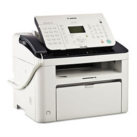
Canon L100 Series Service Manual (19 pages)
Brand:
Canon
| Category:
Fax Machine
| Size: 0.2 MB
Table of Contents
Symbols Used
4
Symbol Description
4
Chapter 1 Product Description
13
Product Specifications
17
Advertisement
Advertisement
Related Products
Canon FAXPHONE L190
Canon L120 Series
Canon FAXPHONE L180
Canon L360
Canon L240
Canon L290
Canon MultiPASS L6000
Canon L250
Canon L2000
Canon LaserBase MF5750
Canon Categories
Printer
Digital Camera
All in One Printer
Camcorder
Scanner
More Canon Manuals
Login
Sign In
OR
Sign in with Facebook
Sign in with Google
Upload manual
Upload from disk
Upload from URL