Sign In
Upload
Manuals
Brands
Brother Manuals
Sewing Machine
PR655C
Brother PR655C Embroidery Machine Manuals
Manuals and User Guides for Brother PR655C Embroidery Machine. We have
2
Brother PR655C Embroidery Machine manuals available for free PDF download: Service Manual, Installation Manual
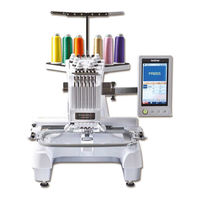
Brother PR655C Service Manual (342 pages)
Brand:
Brother
| Category:
Sewing Machine
| Size: 23.17 MB
Table of Contents
Main Mechanisms
13
Driveline
14
Positions of Electronic Components
16
Control System Block Diagram
18
Layout for P.C.B. Connectors
19
Operation of Other Electronic Components
21
Disassembly
22
Main Parts
27
Needle Thread Unit
49
Needle Thread Assembly Removal
50
Hook Holder Assembly Removal
51
TH Motor Assembly Removal
52
Needle Bar Change Unit
53
Change Box Center Cover Removal
54
Change Box Disassembly (Step 1)
55
Change Box Disassembly (Step 2)
56
Thread Wiper Unit
57
LED Unit Left Assy Removal
58
Wiper Set Assembly Removal
59
Wiper Set Disassembly
60
Needle Bar Unit
61
LED Unit Left Assy Disassembly
62
LED Cord Guide Removal
63
Thread Take-Up Lever Assembly Removal
64
Needle Bar Removal
65
Case Positioning Plate Assembly Removal
66
Case Bracket Assembly Removal
67
Case Bracket Disassembly
68
Upper Shaft Unit
69
Main Motor Final Assembly Removal
70
Main Motor Disassembly
71
Driving Jump Disassembly
72
Base Needle Bar Removal
73
Presser Foot Vertical Base Disassembly
74
Thread Take-Up Driving Lever Disassembly
75
Main Shaft Sensor Final Assembly Removal
76
Pressure Foot Driving Shaft Assembly Removal
77
Upper Shaft Assembly Removal
78
Lower Shaft Unit
79
Arm Bed and Base Frame Disconnection
80
Lower Shaft Removal
81
Power Unit
82
Power Switch Assembly and Inlet Removal
83
Adjust-Bolt Removal
84
Thread Cut Unit
85
Picker Disassembly
86
Cutter Unit Disassembly (Step 1)
87
Cutter Unit Disassembly (Step 2)
88
Thread Tension Unit
89
Loosen the Tension Nut Removal
90
Inner Thread Eyelet Base Removal
91
Upper Thread Eyelet Base Removal
92
Antenna Disassembly
93
Spool Stand Frame Disassembly (Step 1)
94
Thread Take-Up Lever Cover Disassembly (Step 1)
95
Thread Take-Up Lever Cover Disassembly (Step 2)
96
Thread Take-Up Bracket Disassembly
97
Operation Panel
98
Operation Panel Lever Assembly Removal
99
Panel Holder Removal
100
Panel Rear Cover Removal
101
Card Cover Removal
102
Panel PCB Case Removal
103
Board Supporter Removal
104
LCD Supply Assy Disassembly
105
SS PCB Assy Removal
106
Assembly
107
Operation Panel
108
Speaker Set Attachment
109
Attachment of LCD Supply Assy
110
Board Supporter Attachment
111
Panel PCB Case Attachment
112
Pen Holder Attachment
113
Panel Rear Cover Attachment
114
Operation Panel Lever a Attachment
115
Operation Panel Lever Assembly Attachment
116
Thread Tension Unit
117
Thread Take-Up Bracket Assembly
118
Thread Take-Up Lever Cover Assembly (Step 1)
119
Thread Take-Up Lever Cover Assembly (Step 2)
120
Spool Stand Frame Assembly (Step 1)
121
Antenna Assembly (Step 1)
122
Antenna Assembly Attachment
123
Thread Sensor Assembly and Head PCB Assembly Attachment
124
Inner Thread Eyelet Base Attachment
125
Tension Base Lead Wire Assembly Attachment
126
Tension Nut Attachment
127
Thread Cut Unit
128
Cutter Unit Assembly (Step 1)
129
Cutter Unit Assembly (Step 2)
130
Picker Assembly
131
Power Unit
132
Adjust Bolt Attachment
133
Power Supply Unit Attachment
134
EX Connector Holder Attachment
135
Lower Shaft Unit
136
Lower Shaft Attachment
137
Idle Pulley Assembly
138
Connection of Arm Bed and Base Frame
139
Upper Shaft Unit
140
Upper Shaft Assembly
141
Upper Shaft Assembly Attachment
142
Presser Foot Driving Shaft Assembly
143
Presser Foot Driving Shaft Assembly Attachment
144
Crank Rod Assembly Attachment
145
Main Shaft Sensor Final Assembly Attachment
146
Thread Take-Up Driving Lever Final Assembly
147
Thread Take-Up Driving Lever Final Assembly Attachment
148
Vertical Set Assembly
149
Base Needle Bar Attachment
150
Driving Jump Assembly (1)
151
Driving Jump Assembly (2)
152
Driving Jump Assembly Attachment
153
Main Motor Final Assembly
154
Needle Bar Unit
155
Case Guide UL Assembly
156
Case Bracket Assembly
157
Case Bracket Assembly Attachment
158
Case Positioning Plate Assembly
159
Needle Bar Attachment
160
Thread Take-Up Lever Assembly
161
Thread Take-Up Lever Assembly Attachment
162
Case Guide D Attachment
163
Needle Bar Case Final Assembly Attachment
164
LED Cord Guide Attachment
165
LED Unit Left Assy Assembly
166
Thread Wiper Unit
167
Wiper Set Assembly
168
Wiper Guide and Wiper Sensor Attachment
169
Wiper Set Assembly Attachment
170
Thread Presser Base Assembly
171
Needle Bar Change Unit
172
Change Box Assembly (Step 1)
173
Change Box Assembly (Step 2)
174
Change Box Assembly (Step 3)
175
Change Box Center Cover Attachment
176
Needle Thread Unit
177
TH Motor Assembly Attachment
178
Hook Assembly
179
Needle Thread Assembly Attachment
180
Feed Unit
181
Connect PCB Final Assembly
182
Y-Carriage L Assembly
183
Feed Frame Assembly
184
T-Belt (Y-Drive) Attachment
185
X-Guide Shaft Attachment
186
Hoop Sensor Attachment
187
X-Sensor Dog Attachment
188
X-Carriage a Assembly and X-Carriage B Assembly Attachment
189
X-Feed Frame B Attachment
190
Y-Frame Spacer and X-Belt Presser Attachment
191
Cord Grip Attachment
192
Y Driving Shaft Assembly Attachment
193
Y Motor Final Assembly Attachment
194
Feed Final Assembly Attachment
195
T-Belt (Y-Guide) Attachment
196
Main Unit
197
Cutter Unit Final Assembly and Picker Final Assembly Attachment
198
Rotary Hook Attachment
199
Needle Plate Base Assembly
200
Needle Plate Base Assembly Attachment
201
Tension Base Attachment
202
Thread Take-Up Lever Cover Attachment
203
Operation Panel Assembly Attachment
204
Board Holder U/D Attachment
205
Main PCB Assembly Attachment
206
LED PCB Plate Attachment
207
Base Cover R Attachment
208
Arm Cover L Attachment
209
Arm Cover R Attachment
210
Bed Cover Attachment
211
Motor Cover / Carriage Cover Attachment
212
Adjustment
213
Needle Point Damage
214
Starting Test Mode
215
Input Needle Bar Data for Adjustment
225
Motor Belt Tension
227
Timing Belt Tension
228
Needle Drop (Front/Back)
229
Needle Position (Left/Right)
231
Needle Bar Rising and Needle Clearance
232
Needle Bar Height
234
Rotary Hook Stopper Clearance
236
Presser Foot Height
237
Needle Bar Top Dead Center
238
Needle Threader (Up/Down)
239
Needle Threader (Left/Right)
241
Y Belt Tension
242
X Belt Tension
243
Picker Activation
244
Movable Knife Initial Position
245
Thread Presser Base Up/Down Position
246
Hoop Sensor (A/D Value)
247
Upper Shaft Encoder Phase
249
X, y Carriage Initial Position
250
Movable Knife and Fixed Knife Engagement Load
251
Movable Knife and Fixed Knife Pre-Conditioning
252
LED Pointer Position
253
Failure Investigation for Electronic Parts
256
Error Message List
257
The Power Is Not Turned on
258
The Touch Panel Does Not Work
261
The Panel Switch Does Not Work
262
The Needle Bar Does Not Move Normally
263
Thread Breakage Detection Does Not Function Normally
264
The Hoop Does Not Move Normally
265
The Main Shaft Does Not Rotate Normally
267
Thread Is Not Cut Normally
269
The Wiper Does Not Function Normally
270
A Needle Is Not Threaded Normally
271
The Picker Does Not Function Normally
272
LED Light Does Not Turn on
273
USB Function and USB Media Cannot be Used Normally
274
The Hoop Sensor Does Not Function Normally
275
Sound Does Not Work
278
LED Pointer Does Not Light
279
Cannot Upgrade Software
280
Error Message
282
Replacement of Main PCB Assy or Panel PCB Assy
287
Correspondence Table of "Model" and "Printed-Circuit Board"
288
Maintenance & Replacement
289
How to Reset the Counter of the Maintenance
290
Necessary Grease & Oil
291
Maintenance Point (Every 1,500 Hours)
292
Maintenance Point (Every 500 Hours)
298
Maintenance Point (Every Day)
299
Replacement Parts Location
300
Main PCB Assy
301
Power Supply PCB Unit
304
Main Motor Assy
305
Panel PCB and LCD Module
308
Head Unit
310
Hook Holder
311
Sub Tension Assy
312
Special Instructions of Wiring
313
Advertisement
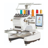
Brother PR655C Installation Manual (64 pages)
Clamp Frame
Brand:
Brother
| Category:
Sewing Machine
| Size: 20 MB
Table of Contents
Attaching the Embroidery Frame
5
Starting Embroidering
6
Vérification du Contenu de L'emballage
15
Fixation du Cadre de Broderie
17
Verifica del Contenuto Della Confezione
27
Colocación del Bastidor de Bordado
35
Advertisement
Related Products
Brother PR-650
Brother PR-650C
Brother Entrepreneur PR650e
Brother PR655
Brother PR-600II
Brother PR-600IIC
Brother PR-620
Brother PR-620C
Brother PR-600
Brother PR-600C
Brother Categories
Sewing Machine
All in One Printer
Printer
Label Maker
Fax Machine
More Brother Manuals
Login
Sign In
OR
Sign in with Facebook
Sign in with Google
Upload manual
Upload from disk
Upload from URL