Sign In
Upload
Manuals
Brands
Bosch Manuals
Control Unit
Rextroth Indramat RECO R-IB IL CNT
Bosch Rextroth Indramat RECO R-IB IL CNT Manuals
Manuals and User Guides for Bosch Rextroth Indramat RECO R-IB IL CNT. We have
1
Bosch Rextroth Indramat RECO R-IB IL CNT manual available for free PDF download: Applications Manual
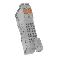
Bosch Rextroth Indramat RECO R-IB IL CNT Applications Manual (116 pages)
Inline Counter Terminal
Brand:
Bosch
| Category:
Control Unit
| Size: 1 MB
Table of Contents
Table of Contents
3
Fig. 1-1: the R-IB IL CNT Terminal with Its Appropriate Connectors
7
Functional Description of the Terminal
7
Functional Description
7
Features of the Terminal
7
Areas of Usage
8
Fig. 1-2: Example Configuration for Counting Separately Packed Articles
8
Design of the Terminal
9
Housing Dimensions
9
Fig. 1-3: Dimensions of the Electronics Base of the R-IB IL CNT Terminal
10
Fig. 1-4: Connector Dimensions
10
Assignment of Terminal Points
11
Fig. 1-5: Assignment of Terminal Points
11
Fig. 1-7: Diagnostic and Status Indicators
12
Diagnostic and Status Indicators
12
Fig. 1-6: Connector Assignment
12
Internal Block Diagram
14
Fig. 1-8: Internal Block Diagram of the R-IB IL CNT
14
Important Directions for Use
17
Appropriate Use
17
Introduction
17
Areas of Use and Application
18
Inappropriate Use
18
Fig. 3-1: Hazard Classification (According to ANSI Z535)
19
Introduction
19
Explanations
19
Safety Instructions for Electric Drives and Controls
19
Hazards by Improper Use
20
General Information
21
Protection against Contact with Electrical Parts
23
Protection against Electric Shock by Protective Low Voltage (PELV)
24
Protection against Dangerous Movements
25
Protection against Magnetic and Electromagnetic Fields During Operation and Mounting
27
Protection against Contact with Hot Parts
28
3.10 Protection During Handling and Mounting
28
3.11 Battery Safety
29
3.12 Protection against Pressurized Systems
29
Mounting and Dismounting a Terminal
31
Mounting Instructions for Replacing the Terminal
31
Mounting and Dismounting Counter Terminals / Connecting Lines
31
Voltage Supply
32
Connecting Sensors and Actuators
32
Connection Methods for Sensors and Actuators
32
Connecting a 24 V Sensor
33
Fig. 4-1: Connecting a 24 V Sensor (Example: Counter Input)
33
Fig. 4-2: Terminal Assignment of Terminal with 24 V Sensor
33
Connecting a 5 V Sensor
34
Fig. 4-3: Connecting a 5 V Sensor
34
Fig. 4-4: Terminal Assignment of Terminal with 5 V Sensor
34
Fig. 4-6: Terminal Assignment: Connecting an Actuator
35
Connecting an Actuator
35
Fig. 4-5: Connecting an Actuator
35
Connecting Lines
36
Connecting Unshielded Lines
36
Fig. 4-7: Connecting Unshielded Lines
36
Connecting Shielded Lines Via the Shield Connector
37
Fig. 4-8: Connecting the Shield on the Shielded Connector
37
Fig. 4-9: Aligning the Shield Clip
39
Process Data Operation
41
Assignment of the Process Data Channel
41
Fig. 5-1: Process Picture in the Input/Output (Memory) Area of Your Interface Module
41
Fig. 5-2: Assignment of Output Words
42
Output Words
42
Input Words
43
Fig. 5-3: Assignment of Input Words (Except When after Read Counter )
43
Fig. 5-4: Assignment of Input Words after R Ead Counter
44
6 Commands Used When Working with the Counter Terminal
45
Fig. 6-1: Commands Used in Working with the Counter Terminal
45
Fig. 6-2: Output Word 0 (OUT[0]) Operating Mode Frequency Measurement
46
Frequency Measurement Mode
46
Order of the Commands
46
Fig. 6-3: Parameters for Frequency Measurement
47
Fig. 6-4: Examples for Factor, Resolution and Gate Time
47
Time-Controlled Frequency Measurement
47
Condition-Controlled Frequency Measurement
48
Fig. 6-5: Possibilities for Parameter and Condition at the Gate Input
48
Event Count Mode
49
Fig. 6-6: Counter Pulses Depending on the Condition of the Gate
49
Fig. 6-7: Output Word 0 (OUT[0]) Operating Mode E Vent Count
49
Fig. 6-10: Parameter R: Count Direction
50
Fig. 6-8: F Count Continuation
50
Fig. 6-9: Parameter Gate
50
Fig. 6-11: Parameter Gate
51
Fig. 6-12: Output Word 0 (OUT[0])
51
Time Measurement Mode
51
Fig. 6-13: Parameter Resolution
52
Fig. 6-14: Parameter Out: Output
52
Fig. 6-15: Parameter Method: Type of Measurement
52
Fig. 6-16: Periods and Pulse Duration
52
Fig. 6-17: Comparative Condition Parameter
53
Fig. 6-18: Comparative Conditions
54
Fig. 6-19: Output Word 0 (OUT[0]) Operating Mode Pulse Generator
55
Fig. 6-20: Factor, Desired Frequency, Actual Frequency and Errors
55
Pulse Generator Mode
55
Fig. 6-21: Output Word 0 (OUT[0]) System Settings
56
Fig. 6-22: Use of the Parameters Within the System Settings Command Within the Individual Operating Modes
56
System Settings" Command
56
Fig. 6-23: Input Wiring Parameter
57
Fig. 6-24: most Common Logic Functions of the Source-Gate Link
58
Fig. 6-25: Source Depending on the Inputs and the Source-Gate Link (Common Logical Functions)
58
Fig. 6-26: Source Depending on the Inputs and the Source-Gate Link (Other Logical Functions)
59
Fig. 6-27: Gate-Source Table
59
Fig. 6-28: Gate-Source Table
59
Fig. 6-29: Gate-Source Table with Derivation for the Output Word
59
Default Condition
60
Fig. 6-30: Bus-Reset Behavior Parameter
60
Fig. 6-31: Pulse Duration Parameter
60
Fig. 6-32: Output Word 0 (OUT[0]) "Read Firmware Version
61
Fig. 6-33: Input Word 0 (IN[0]) "Read Firmware Version
61
Fig. 6-34: Input Word 1 (IN[1]) (Example)
61
Read Firmware Version" Command
61
Default End Value (Maximal 24 Bit)
62
Default Start Value (Maximal 24 Bit)
62
Default Start Value" and "Default End Value" Commands
62
Fig. 6-35: Output Word 0 (OUT[0]) Default Start Value
62
Fig. 6-36: Output Word 1 (OUT[1]) Default Start Value
62
Fig. 6-37: Output Word 0 (OUT[0]) Default End Value
62
Fig. 6-38: Output Word 1 (OUT[1]) Default End Value
62
Fig. 6-39: Output Word 0 (OUT[0]) Counter Stop
63
Fig. 6-40: Output Word 0 (OUT[0]) Counter Start
63
Stop Counter" and "Start Counter" Commands
63
6.10 "Set Counter to Default Condition" Command
64
Fig. 6-41: Output Word 0 (OUT[0]) Setting Counter to Default Position
64
6.11 "Read Counter" Command
65
Fig. 6-42: Output Word 0 (OUT[0]) Read Counter
65
Fig. 6-43: Assignment of the Input Word after the Read Counter Command
65
6.12 Limit Values and Limits to the Commands
67
6.13 Survey of All Commands
67
Fig. 6-44: Limit Values and Limitations
67
Fig. 6-45: Output Word 0 (OUT[0]) Frequency Measurement
68
Fig. 6-46: Output Word 0 (OUT[0]) Event Count
68
Fig. 6-47: Output Word 0 (OUT[0]) Time Measurement
68
Fig. 6-48: Output Word 0 (OUT[0]) Pulse Generator
68
Fig. 6-49: Output Word 0 (OUT[0]) System Settings
68
Fig. 6-50: Output Word 0 (OUT[0]) "Read Firmware Version
69
Fig. 6-51: Output Word 0 (OUT[0]) Starting Value
69
Fig. 6-52: Output Word 1 (OUT[1]) Starting Value
69
Fig. 6-53: Output Word 0 (OUT[0]) Default End Value
69
Fig. 6-54: Output Word 1 (OUT[1]) Default End Value
69
Fig. 6-55: Output Word 0 (OUT[0]) Counter Stop
69
Fig. 6-56: Output Word 0 (OUT[0]) Counter Start
70
Fig. 6-57: Output Word 0 (OUT[0]) Setting Counter to Default Position
70
Fig. 6-58: Output Word 0 (OUT[0]) Read Counter
70
Example for Event Counting
71
Examples and Hints
71
Fig. 7-1: Example Wiring for an Event Count
71
Fig. 7-2: Output Word 1 for the Event Count
71
Fig. 7-3: Example for Event Counting
72
Example for a Time Measurement with Comparative Conditions
73
Fig. 7-4: Output Word 1 (OUT[0]) for the Time Measurement
73
Fig. 7-5: Programming the Example of a Time Measurement with Comparative Condition
74
Fig. 7-6: Example of a Hysteresis
74
Example for a Time Measurement Using System Settings
75
Fig. 7-7: Example Wiring for a Time Measurement with Source and Gate
75
Fig. 7-8: OR-Link of Source and Gate
76
Fig. 7-9: Output Word 0 (OUT[0]) System Settings OR-Link of Source and Gate
76
Fig. 7-10: Output Word 1 (OUT[0]) for the Time Measurement
77
Fig. 7-11: Example for a Time Measurement Using the System Controls
78
Tips for Working with the Counter Terminal
79
Fig. 7-12: Example for the Setting of a Start Value
80
Fig. 8-1: R-IB IL 24 DO 4 Programming Data
83
Programming Data
83
Programming, Technical Data and Ordering Information
83
Fig. 8-2: Output Word for Configuration of Terminal Word 0
84
Fig. 8-3: Output Word for Configuration of Terminal Word 1
84
Output Data Words for Configuring the Terminal
84
Process Data Words
84
Fig. 8-4: Input Data Words During Configuration of Word 0
85
Fig. 8-5: Input Data Words During Configuration of Word 1
85
Fig. 8-6: Input Words after Issuing the Read Counter Word 0 Command
85
Fig. 8-7: Input Words after Issuing the Read Counter Word 1 Command
85
Input Data Words
85
Fig. 8-10: Environmental Conditions
86
Fig. 8-8: General Technical Data
86
Fig. 8-9: Data Transfer
86
Technical Data
86
Fig. 8-11: Compliance with the EMC Guideline 89/336/EEC
87
Fig. 8-12: Technical Data of the Local Bus
87
Fig. 8-13: Power Supply to the Module Electronics and the Periphery Equipment by the Bus Terminal / Power Terminal
87
Fig. 8-14: 7.5 V Supply of the Bus Logic Voltage (U L )
87
Fig. 8-16: Technical Data of the Power Distribution
87
Fig. 8-17: Digital Inputs
88
Fig. 8-18: Input Characteristic
89
Fig. 8-19: De-Rating Input
89
Fig. 8-20: Switch Output
90
Fig. 8-21: Output Characteristics
90
Fig. 8-22: De-Rating Output
90
Fig. 8-23: Sensor Supply Voltage
91
Fig. 8-24: Output Characteristic of Sensor Power Supply
91
Fig. 8-25: De-Rating of Sensor Power Supply
91
Ordering Information
94
10 List of Figures
101
Index
105
12.1 Helpdesk
109
12.2 Service-Hotline
109
12.3 Internet
109
Service & Support
109
Vor der Kontaktaufnahme
109
12.5 Kundenbetreuungsstellen - Sales & Service Facilities
110
Advertisement
Advertisement
Related Products
Bosch REXROTH DBD
Bosch Rexroth IndraControl
Bosch Rexroth IMpdp
Bosch Rexroth IMdev
Bosch Rexroth FMB
Bosch Rexroth XE
Bosch rexroth SM
Bosch rexroth SX
Bosch Rexroth FMS
Bosch Rexroth ctrlX CORE
Bosch Categories
Dishwasher
Washer
Oven
Power Tool
Dryer
More Bosch Manuals
Login
Sign In
OR
Sign in with Facebook
Sign in with Google
Upload manual
Upload from disk
Upload from URL