Sign In
Upload
Manuals
Brands
AMD Manuals
Computer Hardware
780E
AMD 780E Manuals
Manuals and User Guides for AMD 780E. We have
1
AMD 780E manual available for free PDF download: Technical Reference Manual
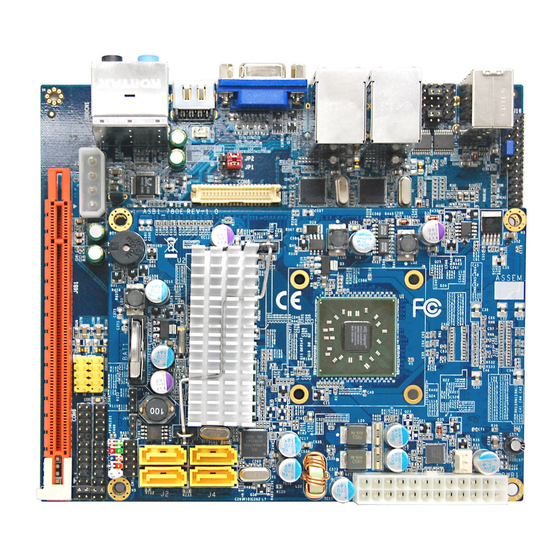
AMD 780E Technical Reference Manual (102 pages)
Databook
Brand:
AMD
| Category:
Computer Hardware
| Size: 2.06 MB
Table of Contents
Table of Contents
3
List of Tables
9
Chapter 1: Overview
11
Introducing the AMD 780E
11
RS780E Features
12
CPU Hypertransport™ Interface
12
Memory Interface
12
ATI Hypermemory
12
PCI Express® Interface
13
Figure 1-1 Possible Configurations for the X16 PCI-E Graphics Interface
13
Table 1-1 Possible Configurations for the PCI-E General Purpose Links
13
A-Link Express II Interface
14
Acceleration Features
14
Motion Video Acceleration Features
15
Multiple Display Features
15
Figure 1-2 RS780E Multiple Display Options
16
1.2.10 Integrated LVDS/TMDS (LVTM) Interface
17
DVI/Hdmi
17
1.2.12 Displayport™ Interface
17
1.2.13 Integrated HD Audio Controller and Codec
18
1.2.14 Clock Generation
18
1.2.15 Power Management Features
18
1.2.16 PC Design Guide Compliance
18
1.2.17 Test Capability Features
19
1.2.18 Additional Features
19
1.2.19 Packaging
19
Software Features
19
Branding Diagram
20
Graphics Device ID and Graphics Engine Clock Speed
20
Conventions and Notations
20
Pin Names
20
Pin Types
20
Figure 1-3 RS780E ASIC A13 Production Branding
20
Table 1-2 Graphics Device ID and Graphics Engine Clock Speed
20
Table 1-3 Pin Type Codes
20
Numeric Representation
21
Register Field
21
Hyperlinks
21
Acronyms and Abbreviations
21
Table 1-4 Acronyms and Abbreviations
21
Chapter 2: Functional Descriptions
23
Host Interface
23
Figure 2-1 RS780E Internal Block Diagram
23
Figure 2-2 Host Interface Block Diagram
24
Side-Port Memory Interface
25
DDR2 Memory Interface
25
Figure 2-3 RS780E Host Bus Interface Signals
25
2.2.1.1 Supported DDR2 Components
26
2.2.1.2 Row and Column Addressing
26
Figure 2-4 RS780E Side-Port Memory Interface
26
Table 2-1 Supported DDR2 Components
26
Table 2-2 DDR2 Memory Row and Column Addressing
26
DDR3 Memory Interface
27
2.2.2.1 Supported DDR3 Components
27
2.2.2.2 Row and Column Addressing
27
Table 2-3 Supported DDR3 Components
27
Table 2-4 DDR3 Memory Row and Column Addressing
27
LVTM (LVDS/TMDS) Interface
28
Figure 2-5 LVTM Interface of the RS780E
28
Lvds
29
2.4.1 LVDS Data Mapping
29
Figure 2-6 Single/Dual Channel 18-Bit LVDS Data Transmission Ordering
29
Table 2-5 LVDS 18-Bit TFT Single Pixel Per Clock (Single Channel) Signal Mapping
30
Table 2-6 LVDS 18-Bit TFT Dual Pixel Per Clock (Dual Channel) Signal Mapping
31
Figure 2-7 Single/Dual Channel 24-Bit LVDS Data Transmission Ordering
32
Table 2-7 LVDS 24-Bit TFT Single Pixel Per Clock (Single Channel) Signal Mapping
33
LVDS Spread Spectrum
34
Table 2-8 LVDS 24-Bit TFT Dual Pixel Per Clock (Dual Channel) Signal Mapping
34
DVI/Hdmi
35
DVI/HDMI™ Data Transmission Order and Signal Mapping
35
Figure 2-8 Data Transmission Ordering for the TMDS Interfaces
35
Table 2-9 Single Link Signal Mapping for DVI/HDMI
36
Table 2-10 Dual-Link Signal Mapping for DVI
37
Support for HDMI™ Packet Types
38
Table 2-11 Support for HDMI™ Packet Type
38
VGA DAC Characteristics
39
Table 2-12 VGA DAC Characteristics
39
DVI-I Support
40
Clock Generation
40
Figure 2-9 Pins for Analog Output on the DVI-I Connector
40
Chapter 3 : Pin Descriptions and Strap Options
42
Pin Assignment Top View
42
RS780E Pin Assignment Top View
42
Figure 3-1 RS780E Pin Assignment Top View (Left)
42
Figure 3-2 RS780E Pin Assignment Top View (Right)
43
Interface Block Diagram
44
Figure 3-3 RS780E Interface Block Diagram
44
CPU Hypertransport™ Interface
45
Side-Port Memory Interface
45
Table 3-1 CPU Hypertransport™ Interface
45
Table 3-2 Side-Port Memory Interface
45
PCI Express® Interfaces
46
X 16 or 2 X 8 Lane Interface for External Graphics
46
A-Link Express II Interface for Southbridge
46
X 1 Lane Interface for General Purpose External Devices
46
Miscellaneous PCI Express® Signals
46
Table 3-4 1 X 4 Lane A-Link Express II Interface for Southbridge
46
Clock Interface
47
CRT Interface
47
Table 3-7 Clock Interface
47
Table 3-8 CRT Interface
47
LVTM Interface
48
LVTM Interface in LVDS Mode
48
LVTM Interface in TMDS Mode
49
Table 3-10 LVTM Interface in TMDS Mode
49
TMDS Interface Multiplexed on the PCI Express® Graphics Lanes
50
Displayport™ Interface
50
AMD 780E Databook
50
Power Management Pins
51
Table 3-13 Power Management Pins
51
Miscellaneous Pins
52
Power Pins
52
Table 3-14 Miscellaneous Pins
52
Table 3-15 Power Pins
52
Ground Pins
53
Table 3-16 Ground Pins
53
Strapping Options
54
Table 3-17 Strap Definitions for the RS780E
55
Chapter 4: Timing Specifications
57
Table 4-1 Timing Requirements for Hypertransport Reference Clock (100Mhz) Output by the Clock Generator
57
PCI Express® Differential Clock AC Specifications
58
Side-Port Memory Timing for DDR2 Mode
58
Read Cycle DQ/DQS Delay
58
Table 4-2 PCI-E Differential Clock (GFX_REFCLK, GPPSB_REFCLK, 100Mhz) AC Characteristics
58
Table 4-3 Timing Requirements for REF_CLKP Used as OSCIN (14.3181818Mhz)
58
Write Cycle DQ/DQS Delay
59
Timing Requirements for REFCLK_P Used as OSCIN (14.3181818Mhz)
58
LVDS Timing
59
Table 4-4 Timing Requirements for the LVTM Interface in LVDS Mode
59
Figure 4-1 RS780E Power Rail Power-Up Sequence
60
Power Rail Power-Up Sequence
60
Table 4-5 RS780E Power Rail Power-Up Sequence
60
Figure 4-2. LCD Panel Power Up/Down Timing
61
LCD Panel Power Up/Down Timing
61
Table 4-6 LCD Power Up/Down Timing
61
Chapter 5 : Electrical Characteristics and Physical Data
63
Electrical Characteristics
63
Maximum and Minimum Ratings
63
Table 5-1 Maximum and Minimum Ratings
63
DC Characteristics
64
Table 5-2 DC Characteristics for 3.3V TTL Signals
64
Table 5-3 DC Characteristics for DDC Signals (DDC Mode)
64
Table 5-4 DC Characteristics for aux Signals (aux Mode)
64
Table 5-5 DC Characteristics for POWERGOOD
65
Table 5-7 DC Characteristics for REFCLK_P Input for OSCIN (14.3181818Mhz)
65
Table 5-8 DC Characteristics for the Memory Interface When Supporting DDR2
65
Table 5-9 DC Characteristics for the Memory Interface When Supporting DDR3
66
Table 5-10 DC Characteristics for the LVTM Interface in TMDS Mode
66
Figure 5-1 DC Characteristics of the TMDS Interfaces
67
Table 5-11 DC Characteristics for the TMDS Interface Multiplexed on the PCI-E Gfx Lanes
67
Figure 5-2 DC Characteristics of the LVDS Interface
68
Table 5-12 Electrical Requirements for the LVTM Interface in LVDS Mode
68
RS780E Thermal Characteristics
69
RS780E Thermal Limits
69
Table 5-13 Electrical Specifications for the Displayport™ Interface
69
Table 5-14 RS780E Thermal Limits
69
Thermal Diode Characteristics
70
Package Information
71
Figure 5-1 RS780E 528-Pin FCBGA Package Outline
71
Physical Dimensions
71
Table 5-15 RS780E 528-Pin FCBGA Package Physical Dimensions
71
Figure 5-2 RS780E Ball Arrangement (Bottom View)
72
Pressure Specification
72
Board Solder Reflow Process Recommendations
73
Figure 5-3 Recommended Stencil Opening Sizes for Solder Paste Pads on PCB
73
Reflow Profile
73
Stencil Opening Size for Solder Paste Pads on PCB
73
Figure 5-4 Rohs/Lead-Free Solder (SAC305/405 Tin-Silver-Copper) Reflow Profile
74
Table 5-16 Recommended Board Solder Reflow Profile - Rohs/Lead-Free Solder
74
Chapter 6: Power Management and ACPI
75
ACPI Power Management Implementation
75
Table 6-1 ACPI States Supported by the RS780E
75
Table 6-2 ACPI Signal Definitions
75
Power Management for the Graphics Controller
76
PCI Function Power States
76
PCI Power Management Interface
76
Capabilities List Data Structure in PCI Configuration Space
76
Table 6-3 Standard PCI Configuration Space Header Type 0
76
Register Block Definition
77
Table 6-4 PCI Status Register
77
Table 6-6 Power Management Register Block
77
Capability Identifier: CAP_ID (Offset = 0)
78
Figure 6-1: Linked List for Capabilities
78
Table 6-7 Power Management Control/Status Register (PMCSR)
78
Next Item Pointer (Offset = 1)
79
PMC - Power Management Capabilities (Offset = 2)
80
Table 6-10 Power Management Capabilities - PMC
80
Chapter 7: Testability
81
Test Capability Features
81
Test Interface
81
XOR Test
81
Description of a Generic XOR Tree
81
Table 7-1 Pins on the Test Interface
81
Description of the RS780E XOR Tree
82
XOR Tree Activation
82
XOR Tree for the RS780E
82
Figure 7-1 Example of a Generic XOR Tree
82
Table 7-2 Example of an XOR Tree
82
Table 7-3 RS780E XOR Tree
83
VOH/VOL Test
84
Description of a Generic VOH/VOL Tree
84
Figure 7-2 Sample of a Generic VOH/VOL Tree
85
Table 7-4 Truth Table for the VOH/VOL Tree Outputs
85
VOH/VOL Tree Activation
85
VOH/VOL Pin List
86
Advanced Micro Devices, Inc
87
Table 7-5 RS780E VOH/VOL Tree
87
Appendix A Pin Listings
89
RS780E Pin List Sorted by Ball Reference
90
RS780E Pin List Sorted by Pin Name
95
Appendix B Revision History
101
Advertisement
Advertisement
Related Products
AMD 770
AMD AMD 785G
AMD 780V Series
AMD 780G
AMD 7ZMMC
AMD 7ZXR
AMD 7ZX Series
AMD 790X
AMD 760G
AMD 740G
AMD Categories
Video Card
Computer Hardware
Motherboard
Microcontrollers
Software
More AMD Manuals
Login
Sign In
OR
Sign in with Facebook
Sign in with Google
Upload manual
Upload from disk
Upload from URL