Sign In
Upload
Manuals
Brands
Alinx Manuals
Motherboard
ZYNQ UltraScale+ AXU5EV-E
Alinx ZYNQ UltraScale+ AXU5EV-E Manuals
Manuals and User Guides for Alinx ZYNQ UltraScale+ AXU5EV-E. We have
2
Alinx ZYNQ UltraScale+ AXU5EV-E manuals available for free PDF download: User Manual
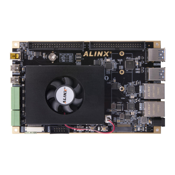
Alinx ZYNQ UltraScale+ AXU5EV-E User Manual (66 pages)
FPGA Development Board
Brand:
Alinx
| Category:
Motherboard
| Size: 4 MB
Table of Contents
Version Record
2
Table of Contents
3
Part 1: FPGA Development Board Introduction
7
Part 2: ACU5EV Core Board
12
Part 2.1: ACU5EV Core Board Introduction
12
Part 2.2: ZYNQ Chip
13
Part 2.3: DDR4 DRAM
15
Part 2.4: QSPI Flash
22
Part 2.5: Emmc Flash
23
Part 2.6: Clock Configuration
25
Part 2.7: LED
27
Part 2.8: Power Supply
28
Part 2.9: ACU5EV Core Board Size Dimension
29
Part 2.10: Board to Board Connectors Pin Assignment
29
Part 3: Carrier Board
38
Part 3.1: Carrier Board Introduction
38
Part 3.2: M.2 Interface
38
Part 3.3: DP Interface
39
Part 3.4: USB3.0 Interface
41
Part 3.5: Gigabit Ethernet Interface
42
Part 3.6: USB to Serial Port
44
Part 3.7: SD Card Slot Interface
46
Part 3.8: HDMI Output Interface
47
Part 3.9: HDMI Input Interface
48
Part 3.10: SFP Interface
50
Part 3.11: Pcie Slot
52
Part 3.12: CAN Communication Interface
53
Part 3.13: 485 Communication Interface
54
Part 3.14: MIPI Camera Interface
55
Part 3.15: FMC Interface
56
Part 3.16: JTAG Debug Port
59
Part 3.17: Real-Time Clock
60
Part 3.18: EEPROM and Temperature Sensor
60
Part 3.19: User Leds
61
Part 3.20: Keys
62
Part 3.21: DIP Switch Configuration
63
Part 3.22: Power Supply
64
Part 3.23: ALINX Customized Fan
65
Part 3.24: Carrier Board Size Dimension
66
Advertisement
Alinx ZYNQ UltraScale+ AXU5EV-E User Manual (56 pages)
FPGA Development Board
Brand:
Alinx
| Category:
Motherboard
| Size: 3 MB
Table of Contents
Version Record
2
Table of Contents
3
Part 1: FPGA Development Board Introduction
6
Part 2: ACU5EV Core Board
10
Part 2.1: ACU5EV Core Board Introduction
10
Part 2.2: ZYNQ Chip
11
Part 2.3: DDR4 DRAM
13
Part 2.4: QSPI Flash
20
Part 2.5: Emmc Flash
21
Part 2.6: Clock Configuration
23
Part 2.7: LED
25
Part 2.8: Power Supply
26
Part 2.9: ACU5EV Core Board Size Dimension
27
Part 2.10: Board to Board Connectors Pin Assignment
27
Part 3: Carrier Board
36
Part 3.1: Carrier Board Introduction
36
Part 3.2: M.2 Interface
37
Part 3.3: DP Interface
38
Part 3.4: USB3.0 Interface
40
Part 3.5: Gigabit Ethernet Interface
41
Part 3.6: USB to Serial Port
43
Part 3.7: SD Card Slot Interface
44
Part 3.8: 40-Pin Expansion Header
45
Part 3.9: CAN Communication Interface
47
Part 3.10: 485 Communication Interface
48
Part 3.11: MIPI Camera Interface
49
Part 3.12: JTAG Debug Port
50
Part 3.13: Real-Time Clock
51
Part 3.14: EEPROM and Temperature Sensor
51
Part 3.15: User Leds
52
Part 3.16: Keys
53
Part 3.17: DIP Switch Configuration
54
Part 3.18: Power Supply
54
Part 3.19: ALINX Customized Fan
55
Part 3.20: Carrier Board Size Dimension
56
Advertisement
Related Products
Alinx AXU5EV-P
Alinx AXU4EV-E
Alinx AXU2CGA
Alinx AXU9EG
Alinx AXU7EV
Alinx AXU15EG
Alinx ZYNQ UltraScale+ AXU2CG-E
Alinx AXU2CGB-E
Alinx ZYNQ UltraScale+ AXU9EGB
Alinx ZYNQUltraScale+ AXU3EGB
Alinx Categories
Motherboard
Computer Hardware
Control Unit
Single board computers
Microcontrollers
More Alinx Manuals
Login
Sign In
OR
Sign in with Facebook
Sign in with Google
Upload manual
Upload from disk
Upload from URL