Table of Contents
Advertisement
Quick Links
See also:
Instruction Manual
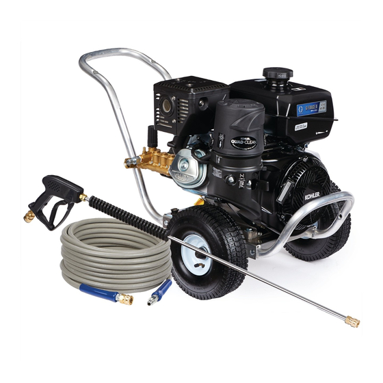
Operation, Repair, Parts
Pressure Washers
For high pressure water cleaning. For professional use only.
See page 2 for model information and maximum working pressure.
Important Safety Instructions
Read all warnings and instructions in this
manual and in the gas engine manual.
Save these instructions.
ti22505a
Direct-Drive Models
333031F
ti22506a
Belt-Drive Models
EN
Advertisement
Table of Contents

Related Manuals for Graco 2525DD


Summary of Contents for Graco 2525DD
- Page 1 Operation, Repair, Parts Pressure Washers 333031F For high pressure water cleaning. For professional use only. See page 2 for model information and maximum working pressure. Important Safety Instructions Read all warnings and instructions in this manual and in the gas engine manual. Save these instructions.
-
Page 2: Table Of Contents
Maintenance ......15 Graco Standard Warranty ....36 Engine . -
Page 3: Safety Symbols And Meanings
Models Safety Symbols and Meanings The following safety symbols appear on the equipment and throughout this manual. It is important that you read the table below and understand what each symbol means. Symbol Meaning Symbol Meaning Do Not Stop Leaks or Deflect Leaks Burn Hazard Do Not Use Flammable Liquids Ejected Parts Hazard... -
Page 4: Warnings
Warnings Warnings The following warnings are for the setup, use, grounding, maintenance, and repair of this equipment. The exclama- tion point symbol alerts you to a general warning and the hazard symbols refer to procedure-specific risks. When these symbols appear in the body of this manual or on warning labels, refer back to these Warnings. Product-specific hazard symbols and warnings not covered in this section may appear throughout the body of this manual where applicable. - Page 5 Pressure Relief Procedure for turning off the unit. • Check hoses and parts for signs of damage. Replace any damaged hoses or parts. • Use Graco replacement parts or accessories that are approved for the rated pressure of the pressure washer.
- Page 6 Warnings WARNING WARNING WARNING WARNING EQUIPMENT MISUSE HAZARD Misuse can cause death or serious injury. • Always wear appropriate gloves, eye protection, and a respirator or mask when spraying. • Do not operate or spray near children. Keep children away from equipment at all times. •...
-
Page 7: Installation
Installation Installation Personal Protective Equipment Once properly installed, check the oil sight glass on the pump crankcase. Make sure the oil level is in the center of the sight glass before each use. If the level appears to be low, add pump oil and fill only to the center of the oil sight glass. -
Page 8: Pressure Relief Procedure
Pressure Relief Procedure Pressure Relief Procedure Follow the Pressure Relief Procedure whenever 5. Trigger gun to relieve pressure. you see this symbol. 6. Engage trigger lock. 7. If you suspect the spray tip or hose is clogged or that pressure has not been fully relieved after follow- ing the steps above, VERY SLOWLY loosen hose This equipment stays pressurized until pressure is end coupling to relieve pressure gradually, then... -
Page 9: Nozzle Review
Pressure Relief Procedure Nozzle Review Various nozzles may be quick-connected into the end of 15° nozzle (YELLOW): This is a chiseling nozzle. The the wand to change the spray pattern or use the deter- spray should be directed at a 45° angle to the surface gent feature. -
Page 10: Nozzle Connection
Pressure Relief Procedure Nozzle Connection 2. Connect other end of hose to pressurized water supply. When connecting water inlet to water supply mains, local regulations of your water company must be observed. In some areas, the unit must not 1. Perform Pressure Relief Procedure, page 8. be connected directly to public drinking water sup- ply. -
Page 11: Unloader
4. Make sure all damaged parts are replaced and mechanical problems are corrected prior to Thermal Relief Valve operation of unit. If service is required, contact Graco To ensure the water temperature does not exceed Customer Service. acceptable levels, never allow the unit to operate in the bypass mode (unit running with gun trigger closed) for more than three minutes. -
Page 12: Operation
Operation Operation Priming the Pump NOTE: Low pressure water will begin flowing from hose/gun assembly. This allows unit to prime and purge any air from system. Unit is primed when It is essential to prime the pump on initial start-up and water flow is uninterrupted by air. -
Page 13: Start-Up
Do not allow spray pattern to remain on a fixed area damaged parts are replaced and mechanical for an extended period of time. Possible damage to problems are corrected prior to operation of unit. If that area may occur. service is required, contact Graco Customer Service. 333031F... -
Page 14: Cleaning With Detergents
Operation Cleaning with Detergents 4. To rinse; engage trigger lock and securely connect desired high pressure nozzle into end of wand. Dis- engage trigger lock and spray. It will take about 30 seconds to purge all detergent from line. For best BURN OR EXPLOSION HAZARD rinsing results, start at the top and work down. -
Page 15: Maintenance
Maintenance Maintenance Engine Quick Couplers The engine instructions that accompany the unit detail There is an o-ring seal inside the female quick coupler. specific procedures for engine maintenance. Following This o-ring will deteriorate or, if the unit is allowed to the engine manufacturer's recommendations will extend pump without the high pressure hose or nozzle engine work life. -
Page 16: Winterizing
Maintenance Winterizing NOTE: Proper winterizing is based on the recom- mended manufacturer’s instructions listed on the Protections Chart shown on the back label of most antifreeze containers. For storage and transportation purposes in subfreezing 6. Remove water supply hose from unit and attach 3 ft ambient temperatures, it will be necessary to winterize hose securely to inlet connection. -
Page 17: Troubleshooting
Troubleshooting Troubleshooting 1. Follow Pressure Relief Procedure, page 12, before checking or repairing gun. 2. Check all possible problems and causes before dis- assembling gun. Problem Cause Solution Engine not starting or hard to start No gasoline in fuel tank or carburetor Fill the tank with gasoline and open fuel shut off valve. - Page 18 Troubleshooting Problem Cause Solution Water in pump oil Humid air condensing inside crank- Change oil as specified in Mainte- case nance on page 15. Worn packings Install new packings. Oil seals are leaking Install new oil seals. Packings failing frequently or prema- Scored, damaged, or worn plungers Install new plungers.
-
Page 19: Parts (Belt-Drive Models)
Parts (Belt-Drive Models) Parts (Belt-Drive Models) Sprayer Parts 27 25 ti22926b 333031F... -
Page 20: Sprayer Parts List
Parts (Belt-Drive Models) Sprayer Parts List Ref. Part Description Qty. Ref. Part Description Qty. 16X819 Models 24U624, 24U625 114703 ENGINE, GX390 (Models 24U624, 24U625, 24U990, 16Y739 Models 24U990, 24U991 24U991) 16C394 Models 24U990, 24U991 Pump 127539 BRACKET, foot (Models 24U624, 127384 GP - TSS series or HP series 24U625, 24U990, 24U991) -
Page 21: Pump 127382
166, 167, 168, 172, 173) 3 valves per kit 127499 KIT, oil seal (includes 98, 106, 121, Kit services 1 cylinder 127, 128) † Not all repair parts available through Graco. 127500 KIT, piston (includes 90) 17A564 THERMAL VALVE, (139) 333031F... -
Page 22: Pump 127384
127490 KIT, valve cap (includes 9, 10) Kit will service 1 cylinder 127491 KIT, oil seal (includes 16) 127492 KIT, packing (includes 44, 47, 56) † Not all repair parts available through Graco. 127493 KIT, piston (includes 35) 17A564 THERMAL VALVE... -
Page 23: Parts (Direct-Drive Models)
Parts (Direct-Drive Models) Parts (Direct-Drive Models) Sprayer Parts ti22925b 333031F... -
Page 24: Sprayer Parts List
Parts (Direct-Drive Models) Sprayer Parts List Ref. Part Description Qty. Ref. Part Description Qty. 16X987 Models 24U626, 24U618 ENGINE 16X988 Models 24U619, 24U985 16Y886 GC160 (Model 24U618) 16X989 Models 24U620, 24U986 16Y887 GC190 (Model 24U626) 16X990 Models 24U621, 24U987 116298 GX200 (Models 24U619, 24U620, 24U895, 24U896) 16X992... -
Page 25: Pump 127383
KIT, oil fill cap, vented w/ o-ring (includes 32) 246377 PUMP, oil, 32 oz 3 valves per kit Kit will service 3 cylinders Kit will service 1 cylinder † Not all repair parts available through Graco. 333031F... -
Page 26: Pump 127417
THERMAL VALVE 17C738 KIT, oil fill cap, vented w/ o-ring (includes 25) 246377 PUMP, oil, 32 oz 802345 SIGHTGLASS (includes 23) Kit will service 3 cylinders Kit will service 1 cylinder † Not all repair parts available through Graco. 333031F... -
Page 27: Pump 127385
PUMP, oil, 32 oz 127486 KIT, oil seal (includes 17) Kit services 3 cylinders 127487 KIT, packing (includes 43, 44, 51) Kit services 1 cylinder 127488 KIT, piston (includes 33) 17A564 THERMAL VALVE † Not all repair parts available through Graco. 333031F... -
Page 28: Pump 127420
THERMAL VALVE 127501 KIT, unloader (includes 9, 11-24) Kit services 3 cylinders 127503 KIT, valves (includes 10) 127504 KIT, water seals (includes 25) † Not all repair parts available through Graco. 127506 KIT, chemical injector (includes 33, 35, 333031F... -
Page 29: Pump 127419
17A562 THERMAL VALVE 127501 KIT, unloader (includes 9, 11-24) Kit services 3 cylinders 127502 KIT, valves (includes 10) 127505 KIT, water seals (includes 25) † Not all repair parts available through Graco. 127506 KIT, chemical injector (includes 33-36) 333031F... -
Page 30: Pump 127418
Parts (Direct-Drive Models) Pump 127418 (Used in 24U987, 24U621) ti22831a Crankcase oil capacity 15 oz (0.44 L) Parts List - Pump 127418 Part Description Qty. 127476 KIT, repair valve (includes 7, 18) 127477 KIT, valve cap (includes 8, 9, 19, 20) 127478... -
Page 31: Technical Data
Technical Data Technical Data 2525DD Models (24U618, 24U626) U.S. Metric Washer Maximum Working Pressure 2500 psi 17.2 MPa, 172bar Honda Engine Size GC190 GC160 Gas Tank Capacity 1.82 quarts 1.7 liters Maximum Delivery 2.5 gpm 9.5 lpm Drive Direct Direct Hose 3/8 in. - Page 32 Technical Data 3027DD Models (24U620, 24U986) U.S. Metric Washer Maximum Working Pressure 2700 psi 18.6 MPa, 186 bar Honda Engine Size GX200 GX200 Gas Tank Capacity 3.8 quarts 3.6 liters Maximum Delivery 3 gpm 11.4 lpm Drive Direct Direct Hose 3/8 in.
- Page 33 Technical Data 4040DD Models (24U988, 24U622) U.S. Metric Washer Maximum Working Pressure 4000 psi 27.6 MPa, 276 bar Honda Engine Size GX390 GX390 Gas Tank Capacity 6.9 quarts 6.5 liters Maximum Delivery 4 gpm 15.1 lpm Drive Direct Direct Hose 3/8 in.
- Page 34 Technical Data 4040BD Models (24U990, 24U624) U.S. Metric Washer Maximum Working Pressure 4000 psi 27.6 MPa, 276 bar Honda Engine Size GX390 GX390 Gas Tank Capacity 6.9 quarts 6.5 liters Maximum Delivery 4 gpm 15.1 lpm Drive Belt Belt Hose 3/8 in.
-
Page 35: Notes
Notes Notes 333031F... -
Page 36: Graco Standard Warranty
With the exception of any special, extended, or limited warranty published by Graco, Graco will, for a period of twelve months from the date of sale, repair or replace any part of the equipment determined by Graco to be defective.
Need help?
Do you have a question about the 2525DD and is the answer not in the manual?
Questions and answers