Table of Contents
Advertisement
Quick Links
Instructions
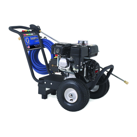
G-Force Direct-Drive Pressure Washer
IMPORTANT SAFETY INSTRUCTIONS
Read all warnings and instructions in this manual.
SAVE THESE INSTRUCTIONS.
-For high pressure water cleaning-
-For outdoor use only-
Model
Horse Power and
Motor Brand
2525
160cc Honda
2730
200cc Honda
3030
270cc Honda
3540
390cc Honda
PROVEN QUALITY. LEADING TECHNOLOGY.
Maximum Working
Pressure
PSI
MPa
bar
2500 17.24 172.4
2700 18.62 186.2
3000 20.68 206.8
3500 24.13 241.3
3A0465B
37-1097 041810
Advertisement
Table of Contents

Related Manuals for Graco 2525


Summary of Contents for Graco 2525
- Page 1 IMPORTANT SAFETY INSTRUCTIONS Read all warnings and instructions in this manual. SAVE THESE INSTRUCTIONS. Model Horse Power and Maximum Working Motor Brand Pressure 2525 160cc Honda 2500 17.24 172.4 2730 200cc Honda 2700 18.62 186.2 3030 270cc Honda 3000 20.68 206.8...
-
Page 2: Table Of Contents
CONTENTS Important ................ 3 Pump Service: 2525 Model Pressure Washers ..17 Spray Precautions ............3 For Outlet Valves ............17 Fire & Ventilation Precautions ........4 For Inlet Valves .............. 17 Carbon Monoxide Hazard ..........4 Servicing Plungers Or Internal Bearings ....... 17 Detergent Cleaning Precautions ........ -
Page 3: Important
The following warnings are for the setup, use, grounding, maintenance, and repair of this equipment. The exclamation point symbol alerts you to a general warning and the hazard symbols refer to procedure-spe- cific risks. When these symbols appear in the body of this manual, refer back to these Warnings. Product- specific hazard symbols and warnings not covered in this section may appear throughout the body of this manual where applicable. -
Page 4: Fire & Ventilation Precautions
WARNING • Do not direct spray on or into electrical installations of any kind! This includes electrical outlets, light bulbs, fuse boxes, transformers, etc. Severe electrical shock may occur. • Even after you shut off the unit, there is high pressure water left in the pump, hose and gun until you release it by triggering the gun. -
Page 5: Miscellaneous Safety Precautions
WARNING MISCELLANEOUS SAFETY PRECAUTIONS Never allow children or adolescents to operate this unit. Read and follow all handling, operations, maintenance and safety instructions listed in this manual and the engine operator’s manual that accompanies this unit, and provide such information to anyone who will be operating this unit. -
Page 6: Component Identification
Component Identification Item Description Detergent Strainer Detergent Hose Water Inlet Water Inlet Strainer Water Outlet Decal - Warning/Caution/Operation Oil Sight Glass Pump Adjustable Unloader Knob Decal - Caution: Risk Of Fire Decal - Warning: Risk Of Burns Engine Thermal Relief Valve High Pressure Discharge Hose Gun Assembly Decal - Warning: Risk Of Injection... -
Page 7: Installation & Preparation Instructions
INSTALLATION & PREPARATION INSTRUCTIONS Do not allow the unit to be exposed to rain, snow or Attire freezing temperatures. If any part of the unit becomes frozen, excessive pressure may build up in the unit which could cause it to burst resulting in possible seri- ous injury to the operator or bystanders. -
Page 8: Engine Fuel Tank
Fill the fuel tank according to accompanying engine dows, washing vehicles, spraying sidewalks, driveways manual instructions. and patios. (not available for Model 2525) Occasional carburetor and choke adjustments will be The 65° nozzle (BLACK): This is a low pressure de- necessary for the engine. -
Page 9: Nozzle Connection
5 gallon container.) NOTICE Incoming water temperature must not exceed 125°F for Model 2525, and 145°F for other models. Exces- sive pump damage may result if the water tempera- Water Supply ture exceeds this acceptable level. -
Page 10: Unloader
NOTICE unit. If you require service, contact Graco Customer Do not overtighten the unloader. Breakage could Service. result in immediate loss of water pressure and... -
Page 11: Operating Instructions
OPERATING INSTRUCTIONS NOTICE Be certain the nozzle is not connected to the unit Priming the Pump while priming the pump. Priming allows mineral de- It is essential to prime the pump on initial start-up and posits to be released from the system which would obstruct or damage the nozzle assembly resulting in each time the water supply is disconnected from the unit after initial use. -
Page 12: Start-Up
If you require Locate the Safety Decals on your unit and heed their service, contact Graco Customer Service. warnings. 6. Trigger the gun several times. Be certain to lock the Never look directly into the nozzle. -
Page 13: Cleaning With Detergents
OPERATING INSTRUCTIONS 3. To apply solution; unlock the trigger gun and squeeze the trigger. In a few moments a detergent/water mixture will exit the low pressure nozzle. Start spraying the Cleaning with Detergents lower portion of the surface being cleaned and move up, using long overlapping strokes. -
Page 14: Storage & Maintenance Instructions
STORAGE & MAINTENANCE Nozzles INSTRUCTIONS Water flow through the spray nozzle will erode the ori- fice, making it larger, resulting in a pressure loss. Noz- zles should be replaced whenever pressure is less than Engine 85% of the maximum. The frequency of replacement The engine instructions that accompany your unit detail will depend upon such variables as mineral content in specific procedures for maintenance of the engine. -
Page 15: Winterizing
2. Relieve system pressure by pointing the trigger gun in • Two 5 gallon containers. a safe direction and squeezing the trigger until water • One gallon of antifreeze. (Graco® recommends an flow ceases to exit the nozzle. environmentally safe antifreeze.) 3. -
Page 16: Troubleshooting
Troubleshooting Problem Cause Solution Engine will not start. Various engine problems. Refer to the engine manual accom- panying your unit. Unit components are frozen. Allow to thaw. If any part of the unit becomes frozen; excessive pres- sure may build up in the unit which could cause the unit to burst result- ing in possible serious injury to the operator or bystanders. -
Page 17: Pump Service: 2525 Model Pressure Washers
PUMP SERVICE: 2525 MODEL Servicing V-Packings PRESSURE WASHERS 1. Remove manifold as described in Valve Replacement Section. 2. Remove white retaining ring, this may be stuck on the Repair kits are available. See the Parts List, page 24. piston. For the best results, use all parts in kits. -
Page 18: Pump Service: 2730 Model Pressure Washers
PUMP SERVICE: 2730 MODEL 5. Lightly grease the flinger (and oil seal if it is being replaced) on plunger shaft. Then install plunger. PRESSURE WASHERS 6. Lightly grease the retaining screw and outer end of the plunger. Place washer, o-ring and backup ring around Repair kits are available. -
Page 19: Pump Service: 3030 And 3540 Model Pressure Washers
PUMP SERVICE: 3030 AND 3540 6. Lightly grease the retaining screw and outer end of the plunger. Place washer, o-ring and backup ring around MODEL PRESSURE WASHERS screw and install nut through plunger. Torque to 11.0 ft-lb (15 Nm). Repair kits are available. See the Parts List, page 32, Note: If replacing packings, see Servicing V-Packings. -
Page 20: Pressure Washer - Parts 262292- Model 2525Dd
Pressure Washer - Parts 262292- Model 2525DD... - Page 21 Pressure Washer - Parts 262292- Model 2525DD DESCRIPTION PART # 15 CAP 16E491 DESCRIPTION PART # 16 BOLT 802127 GROMMET 16E489 17 WASHER 107194 NOZZLE, 0° 805535 18p DECAL - RISK OF FIRE (E/S/F) NOZZLE, 15° 805536 19p DECAL - RISK OF BURNS (E/S/F) NOZZLE, 40°...
-
Page 22: Pump Assembly - Parts 24E735 (For Use With Model 2525Dd)
Pump Assembly - Parts 24E735 (for use with Model 2525DD) - Page 23 Pump Assembly - Parts 24E735 (for use with Model 2525DD) DESCRIPTION PART # QTY KIT, REPAIR, VALVES 24E736 INCLUDES 1 KIT, REPAIR, PLUNGER 24E737 INCLUDES 2 KIT, REPAIR, OIL SEAL 24E738 INCLUDES 3 KIT, REPAIR, UNLOADER 24E739 INCLUDES 4 KIT, REPAIR, PACKINGS 24E740 INCLUDES 5, 6, 7, 8 KIT, REPAIR, CHEMICAL INJECTOR...
-
Page 24: Pressure Washer - Parts 262293- Model 2730Dd
Pressure Washer - Parts 262293- Model 2730DD... - Page 25 Pressure Washer - Parts 262293- Model 2730DD DESCRIPTION PART# DESCRIPTION PART# GROMMET 16E489 21 ENGINE 16E658 NOZZLE, 0° 805535 22p DECAL - RISK OF FIRE (E/S/F) NOZZLE, 15° 805536 23p DECAL - RISK OF BURNS (E/S/F) NOZZLE, 25° 805537 24 DETERGENT HOSE 117760 NOZZLE, 40°...
-
Page 26: Pump Assembly - Parts 244749 (For Use With Model 2730Dd)
Pump Assembly - Parts 244749 (for use with Model 2730DD) - Page 27 Pump Assembly - Parts 244749 (for use with Model 2730DD) DESCRIPTION PART # KIT, REPAIR, VALVES 804402 INCLUDES 24 KIT, REPAIR, OIL SEAL 804033 INCLUDES 36 KIT, REPAIR, PLUNGER 804011 INCLUDES 37 KIT, REPAIR, PACKINGS 804037 INCLUDES 32, 33, 34, 35 KIT, REPAIR, CHEMICAL INJECTOR 24E748 INCLUDES 25-31...
-
Page 28: 262294- Model 3030Dd
Pressure Washer - Parts 262294- Model 3030DD 262295- Model 3540DD... - Page 29 Pressure Washer - Parts 262294- Model 3030DD 262295- Model 3540DD DESCRIPTION PART # DESCRIPTION PART # GROMMET 16E489 19 WASHER 100731 NOZZLE (3030DD), 0° 805539 20 LOCKNUT 101566 NOZZLE (3030DD), 15° 805540 21 ENGINE (3030DD 16E659 NOZZLE (3030DD), 25° 805541 ENGINE (3540DD) 16E660 NOZZLE (3030DD), 40°...
-
Page 30: Pump Assembly - Parts
Pump Assembly - Parts 24E753 (for use with Model 3030DD) 24E750 (for use with Model 3540DD) - Page 31 Pump Assembly - Parts 24E753 (for use with Model 3030DD) 24E750 (for use with Model 3540DD) DESCRIPTION PART # KIT, REPAIR, VALVES 804402 INCLUDES 10 KIT, REPAIR, OIL SEAL 24E744 INCLUDES 18 KIT, PLUNGER 24E745 INCLUDES 22 KIT, REPAIR, PACKINGS 24E746 INCLUDES 11-17 KIT, REPAIR, PLUNGER...
-
Page 32: Notes
Notes... -
Page 33: Technical Data
Technical Data Model 2525 Model 2730 Model 3030 Model 3540 Working Pressure Range 2250-2300 psi 2600-2700 psi 2800-2900 psi 3400-3500 psi Operating Pressure 2275 psi 2650 PSI 2850 PSI 3450 psi Maximum Working Pressure 2500 psi 2700 psi 3000 psi... -
Page 34: Graco Standard Warranty
Graco, Graco will, for a period of twelve months from the date of sale, repair or replace any part of the equipment determined by Graco to be defective. This warranty applies only when the equipment is installed, operated and maintained in accordance with Graco’s written...
Need help?
Do you have a question about the 2525 and is the answer not in the manual?
Questions and answers