Table of Contents
Advertisement
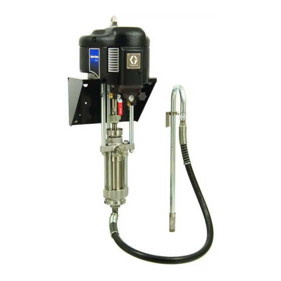
Instructions - Parts
Hydra-Clean
Package solutions for pressure washing applications. For use only with water and cleaning
solutions.
Important Safety Instructions
Read all warnings and instructions in this manual and in
your respective pump manual. Save these instructions.
See page 3 for model information, including maximum working pressure.
Cart Mount Packages
®
Packages
TI11267A
312585E
Wall Mount Packages
II 2 G
ENG
TI11273A
Advertisement
Table of Contents

Subscribe to Our Youtube Channel
Related Manuals for Graco Hydra-Clean 247549


Summary of Contents for Graco Hydra-Clean 247549
- Page 1 Instructions - Parts Hydra-Clean Package solutions for pressure washing applications. For use only with water and cleaning solutions. Important Safety Instructions Read all warnings and instructions in this manual and in your respective pump manual. Save these instructions. See page 3 for model information, including maximum working pressure. Cart Mount Packages ®...
-
Page 2: Table Of Contents
Contents Models ........3 Related Manuals ......3 Warnings . -
Page 3: Models
Models Check your package’s identification plate (ID) for the 6-digit part number of your package. To order replace- ment parts, see Parts starting on page 14. All packages include integrated air controls, hose and gun, and ground wire. Maximum Working Pressure Part No. -
Page 4: Warnings
Warnings Warnings The following warnings are for the setup, use, grounding, maintenance, and repair of this equipment. The exclama- tion point symbol alerts you to a general warning and the hazard symbol refers to procedure-specific risk. Refer back to these warnings. Additional, product-specific warnings may be found throughout the body of this manual where applicable. - Page 5 MOVING PARTS HAZARD Moving parts can pinch or amputate fingers and other body parts. • Keep clear of moving parts. • Do not operate equipment with protective guards or covers removed. • Pressurized equipment can start without warning. Before checking, moving, or servicing equipment, follow the Pressure Relief Procedure in this manual.
-
Page 6: Installation
Installation Installation The Graco warranty will not apply if cleaning solutions other than those recommended by Graco are used in these units. Only use solutions that are not harmful to the wetted parts. See the Technical Data in the displace- ment pump manuals 311825, 311827, and 312745. - Page 7 Detail of Integrated Air Control Module (C) TI8322C . 1: Typical Installation (Cart Mount Package Shown) Displacement Pump Air Motor Integrated Air Control Module (includes items D-H) Bleed-type Master Air Valve (required) Pump Air Regulator Air Pressure Gauge Safety Relief Valve Air Filter (hidden) Air Inlet Air Supply Line...
-
Page 8: Grounding
Installation Grounding Although water generally provides a natural electrical ground, the following equipment must be grounded if the cleaning chemicals are volatile. The equipment must be grounded. Grounding reduces the risk of static and electric shock by providing an escape wire for the electrical current due to static build up or in the event of a short circuit. -
Page 9: Operation
Operation Pressure Relief Procedure Trapped air can cause the pump to cycle unexpectedly, which could result in serious injury from splashing or moving parts. 1. Engage the trigger lock. 2. Close the bleed-type master air valve to shutoff the pump. 3. -
Page 10: Starting The Pump
Operation Starting the Pump 1. Open the bleed-type master air valve (A). 2. Trigger the gun into a grounded metal pail, holding a metal part of the gun firmly to the pail. 3. Slowly open the air regulator (E) until the pump starts running. - Page 11 Operation 312585E...
-
Page 12: Troubleshooting
Troubleshooting Troubleshooting Problem Pump fails to operate. Pump operates, but output low on both strokes. Pump operates, but output low on down- stroke. Pump operates, but output low on upstroke. Erratic or accelerated pump speed. To determine if the fluid hose or gun is obstructed, relieve the pressure, page 9. Disconnect the fluid hose and place a container at the pump fluid outlet to catch any fluid. -
Page 13: Repair
Repair Disconnect the Displacement Pump See the Parts drawings on pages 14-17. 1. Flush the pump, if possible. Stop the pump at the bottom of its stroke. Relieve the pressure, page 9. 2. Disconnect the air, fluid, and suction hoses. Do not lift the pump by the lift ring when the total weight exceeds 250 kg (550 lb). -
Page 14: Parts
Parts Parts 247549 Cart Mount Package See parts listing on page 18. Ref. 20 TI11268A 312585E... -
Page 15: 247550 Wall Mount Package
247550 Wall Mount Package See parts listing on page 18. 312585E Ref. 20 Parts TI11270A... -
Page 16: 247551, 247553, And 258664 Cart Mount Packages
Parts 247551, 247553, and 258664 Cart Mount Packages See parts listing on page 18. Ref. 20 TI11272A 312585E... -
Page 17: 247552, 247554, And 258665 Wall Mount Packages
247552, 247554, and 258665 Wall Mount Packages See parts listing on page 18. 312585E Ref. 20 Parts TI11274A... -
Page 18: Parts Listings
Parts Parts Listings Common Parts The following parts are used on all packages in this manual. Ref. Part Description 100133 WASHER, lock; 3/8 NXT021 CONTROL, air, integrated; with non-locking air regulator; see 311239 244524 WIRE, ground 101712 NUT, lock; 5/8-11 101748 PLUG, pipe;... -
Page 19: Kits
Ref. No. Description ADAPTER; M38 x 2 x 3/4-16 unf ADAPTER; 1 1/4-12 unf x 3/4-16 unf COLLAR, coupling NUT, coupling MANIFOLD, fluid outlet; 1 in. npt(m) x 3/8 npt(f) x 3/8 npt(f) MANIFOLD, fluid outlet; 3/4 npt(f) x 3/8 npt(f) x 3/8 npt(f);... -
Page 20: Wall Mounting Bracket Diagram
Wall Mounting Bracket Diagram Wall Mounting Bracket Diagram 5.4 in. (136.5 mm) 1.6 in. (41.4 mm) 1/2 in. (12.7 mm) diameter holes for mounting to stand 17.8 in. (450.9 mm) 14.5 in. (368.3 mm) 9.0 in. (228.6 mm) 12.4 in. (314.3 mm) 2.0 in. -
Page 21: Dimensions
Dimensions Wall Mount Packages (247550, 247552, 247554) Package in. (mm) in. (mm) in. (mm) 247549 50.0 (1270) 5.6 (142) 247550 44.3 (1125) 30.8 (782) 247551 50.5 (1283) 3.9 (99) 247552 46.4 (1179) 32.5 (826) 247553 50.5 (1283) 4.3 (109) 247554 46.4 (1179) 32.5 (826) 258664... -
Page 22: Technical Data
Technical Data Technical Data Maximum fluid working pressure Part Nos. 247549 and 247550....1250 psi (8.6 MPa, 86.2 bar) Part Nos. 247551 and 247552....2275 psi (15.7 MPa, 156.9 bar) Part Nos. - Page 23 23:1 Ratio Pumps (247551, 247552) 40 psi (0.3 MPa, 3 bar) Air Supply Spray Tip Orifice Size, Pressure in psi in. (mm) gpm (l/min) /min) .030 (0.76) 0.5 (1.9) 7.6 (0.21) 822 (5.7, 57) .045 (1.14) 1.3 (4.9) 16.2 (0.45) 786 (5.5, 55) .060 (1.52) 2.2 (8.3)
-
Page 24: Graco Standard Warranty
Graco Standard Warranty Graco warrants all equipment referenced in this document which is manufactured by Graco and bearing its name to be free from defects in material and workmanship on the date of sale to the original purchaser for use. With the exception of any special, extended, or limited warranty published by Graco, Graco will, for a period of twelve months from the date of sale, repair or replace any part of the equipment determined by Graco to be defective.
Need help?
Do you have a question about the Hydra-Clean 247549 and is the answer not in the manual?
Questions and answers